EP1021118B1 - Sheet material dispenser - Google Patents
Sheet material dispenser Download PDFInfo
- Publication number
- EP1021118B1 EP1021118B1 EP98946621A EP98946621A EP1021118B1 EP 1021118 B1 EP1021118 B1 EP 1021118B1 EP 98946621 A EP98946621 A EP 98946621A EP 98946621 A EP98946621 A EP 98946621A EP 1021118 B1 EP1021118 B1 EP 1021118B1
- Authority
- EP
- European Patent Office
- Prior art keywords
- dispenser
- roll
- door
- aperture
- base
- Prior art date
- Legal status (The legal status is an assumption and is not a legal conclusion. Google has not performed a legal analysis and makes no representation as to the accuracy of the status listed.)
- Expired - Lifetime
Links
Images








Classifications
-
- A—HUMAN NECESSITIES
- A47—FURNITURE; DOMESTIC ARTICLES OR APPLIANCES; COFFEE MILLS; SPICE MILLS; SUCTION CLEANERS IN GENERAL
- A47K—SANITARY EQUIPMENT; ACCESSORIES THEREFOR, e.g. TOILET ACCESSORIES
- A47K10/00—Body-drying implements; Toilet paper; Holders therefor
- A47K10/24—Towel dispensers; Toilet paper dispensers
- A47K10/32—Dispensers for paper towels or toilet paper
- A47K10/34—Dispensers for paper towels or toilet paper dispensing from a web, e.g. with mechanical dispensing means
- A47K10/38—Dispensers for paper towels or toilet paper dispensing from a web, e.g. with mechanical dispensing means the web being rolled-up
- A47K10/3809—Dispensers for paper towels or toilet paper dispensing from a web, e.g. with mechanical dispensing means the web being rolled-up with roll spindles which are not directly supported
- A47K10/3818—Dispensers for paper towels or toilet paper dispensing from a web, e.g. with mechanical dispensing means the web being rolled-up with roll spindles which are not directly supported with a distribution opening which is perpendicular to the rotation axis
Definitions
- This invention generally relates to dispensers. More specifically, this invention relates to sheet material dispensers.
- a sheet material dispenser provides material, such as tissue or paper towels.
- One type of sheet material dispenser may be designed for center feed rolls.
- center feed rolls dispense material from their core rather than their periphery, as opposed to conventional rolls.
- the roll may be stationary as material is dispensed from its center.
- An advantage of center feed rolls is their dispensers do not require moving parts, such as handles and rollers to rotate the roll, which are typically required with conventional roll dispensers.
- center feed roll dispensers are top loading devices that include a mounting plate, a platform, and a cover.
- the mounting plate attaches to a substantially vertical wall and is formed integrally with the platform.
- the platform may form a opening at its center and extend substantially horizontally from the mounting plate.
- the platform may form a flat surface for receiving a center feed roll. Normally, material from the roll is dispensed through the opening.
- the cover may pivotally connect to or be positioned upon the mounting plate.
- the cover may rotate pivotally outward and downward, or be completely removable, to expose the platform permitting the placement of a center feed roll. Once pivoted downward, the cover may be pivoted upwardly to conceal the roll within the dispenser. Often a key locks the cover to the mounting plate for preventing the theft of the roll.
- a locking mechanism such as a key padlock or a combination lock
- a center feed roll provides material from its center, it may be necessary to view either its top or bottom side to check the amount of material available. Opening the cover may fail to reveal the roll's top or bottom side because the roll's top side is often too high to be viewed and the bottom side view is blocked by the platform. As a result, checking the amount of remaining roll material may require opening the cover and removing the roll from the platform.
- WO-A-86/02247 discloses a feeding out device for a material web withdrawable from a roll.
- a material dispenser for a center feed roll that eliminates the need for a locking mechanism, improves serviceability, and prevents moisture, such as water, from reaching the roll will improve over conventional roll dispensers.
- the present invention provides a dispenser for center feed roll products.
- the present invention provides a dispenser for a center feed roll as claimed in claim 1.
- the dispenser includes a base and a cover adapted to fit the base.
- the cover may further define a cavity to receive the center feed roll product.
- the base may further include a roll platform and a securing means.
- the securing means defining an aperture may be coupled to the roll platform and adapted to support a center feed roll product.
- the securing means may permit the installation of a roll product through the aperture and prevent the removal of the roll product.
- the roll dispenser may further include a mounting member coupled to the roll platform.
- the securing means may further include a hinge which may pivot inward into the cavity permitting placement of the roll product within the dispenser and return to a dispensing position to secure the roll product for dispensing.
- the securing means may further indude at least one buttress coupled to the hinge to prevent the hinge from pivoting past the dispensing position.
- the dispenser may further include a supporting means bracing the securing means.
- the supporting means may be a second flap that may include a protrusion and a tab coupled to the base.
- the roll dispenser may further include a door defining an aperture coupled to the base by a living hinge.
- the door may further include a sealing member coupled to the door and a latching assembly coupling the door to the base.
- the sealing member may be positionable to substantially seal the door aperture for preventing liquids from entering the dispenser.
- the dispenser may further include a door defining an aperture coupled to the base.
- the door may include a supporting means having a hinge support coupled to the door, an aperture disc coupled to the door and surrounding the door aperture to aid the tearing of roll products, and a sealing member.
- the aperture disc may be constructed from an elastomeric material.
- the dispenser may further include a latching assembly coupling the door to the base so that the latching assembly may support the weight of the roll product inside of the dispenser.
- the door may include a supporting means and a protruding member coupled to the door.
- the supporting means may further include a protruding member extending in a first direction.
- the protruding member coupled to the door and positioned in the aperture of the door may extend in a second direction substantially opposite of the first direction.
- the cover may be constructed from a semi-transparent material for viewing the roll product within.
- the cover may be constructed from an opaque material forming a window for viewing the roll product within.
- the dispenser may include a base, a cover, a door, and a latching assembly.
- the base further includes a mounting member, a roll platform, and a securing means defining an aperture.
- the mounting member and the securing means may be coupled to the roll platform.
- the securing means may permit the installation of a roll product through the aperture and prevent the removal of the roll product.
- the cover is adapted to fit the base.
- the cover may be constructed from a semi-transparent or translucent material for viewing the roll product within.
- the door defining an aperture is pivotally coupled to the base.
- the door may include a supporting means and a protruding member coupled to the door.
- the supporting means may further include a protruding member extending in a first direction.
- the protruding member coupled to the door and positioned in the aperture of the door may extend in a second direction substantially opposite of the first direction.
- the latching assembly may couple the door to the base and support the weight of the roll product inside of the dispenser.
- the dispenser desirably, includes a base, a cover, a door, and a latching assembly.
- the base may further include a mounting member, a roll platform, and a securing means defining an aperture.
- the mounting member and securing means may be coupled to the roll platform.
- the securing means may permit the installation of a roll product through the aperture and prevent the removal of the roll product.
- the securing means includes a substantially circular member having a plurality of hinges, which pivot substantially upward permitting the placement of the roll product within the dispenser and return substantially horizontal for securing the roll product.
- the cover is adapted to fit the base.
- the cover may be constructed from a semi-transparent or translucent material for viewing the roll product within.
- the cover and base may be sized to receive roll products having a diameter between about 150 millimeters to about 225 millimeters and a width between about 5 millimeters to about 245 millimeters.
- the cover and base may be sized to accommodate other roll sizes.
- the door defining an aperture is coupled to the base.
- the door may include a supporting means and a protruding member coupled to the door.
- the supporting means may further include a protruding member extending in a first direction.
- the protruding member coupled to the door and positioned in the aperture of the door may extend in a second direction substantially opposite of the first direction.
- the latching assembly includes a latch and a catch and couples the door to the base.
- the latching assembly may support the weight of the roll product inside of the dispenser.
- the dispenser for sheet material products defines an aperture permitting only a substantially upward or inward installation of a sheet material product substantially within the dispenser.
- sheet material refers to a material that is thin in comparison to its length and breadth. Generally speaking, sheet materials should exhibit a relatively flat planar configuration and be flexible permitting folding, rolling, stacking, or the like. Exemplary sheet materials include, but not limited to, paper tissue, paper towels, label rolls, or other fibrous, film, polymers, or filamenting products.
- center feed roll product desirably refers to sheet material wound cylindrically about a center, but permitting the removal of material from the center. Desirably, as the center feed roll product is consumed, sheet material eventually dispenses from the roll's periphery.
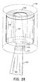
- An exemplary center feed roll product is shown in Figure 28. Center feed roll products are also described by patent publications, such as UK Patent Application 2,308,114A published June 6, 1997.
- mechanical fasteners desirably refers to devices that fasten, join, connect, secure, hold, or clamp components together.
- Mechanical fasteners include, but are not limited to, screws, nuts and bolts, rivets, snap-fits, tacks, nails, loop fasteners, and interlocking male/female connectors, such as fishhook connectors.
- a fish hook connector includes a male portion with a protrusion on its circumference. Inserting the male portion into the female portion substantially permanently locks the two portions together.
- Hinges desirably refers to a jointed or flexible device that connects and permits pivoting or turning of a part to a stationary component.
- Hinges include, but are not limited to, metal pivotable connectors, such as those used to fasten a door to frame, and living hinges.
- Living hinges may be constructed from plastic and formed integrally between two members. A living hinge permits pivotable movement of one member in relation to another connected member.
- Couple includes, but not limited to, joining, connecting, fastening, linking, or associating two things integrally or interstitially together.
- the material dispenser 40 may include a substantially L-shaped base 44, a cover 62, a door 66 and a latching assembly 82.
- the base 44 and cover 62 may be constructed from metal, plastic, or other composite materials.
- the base 44 is constructed from polypropylene and the cover 62 is constructed from polystyrene, polypropylene, polyethylene, or other thermoplastics.
- the cover 62 may connect to the base 44 using any suitable means, such as adhesives, welds, or mechanical fasteners. Alternatively, the cover 62 may be adapted to loosely fit over or formed integrally with the base 44. Regardless of how the cover 62 is connected, desirably the cover 62 and base 44 form a cavity 64 for housing the center feed roll product 42.
- the cover 62 is constructed from a semi-transparent or translucent material permitting viewing of the roll product 42 within.
- the cover 62 may be constructed from an opaque material, and optionally, may surround a transparent material serving as a window.
- the base 44 may include a roll platform 46, a securing means 52, and a mounting member 58.
- the roll platform 46 may be formed integrally with the mounting member 58.
- the roll platform 46 may be formed integrally with a catch 92 of the latching assembly 82, which is described in further detail hereinafter.
- the mounting member 58 may form a plurality of mounting apertures 60a-I permitting attaching of the member 58 with mechanical fasteners to a support structure, such as a wall.
- the mounting member 58 may be fixed to a support structure using any suitable means, such as adhesives or welds.
- the securing means 52 is formed integrally with the roll platform 46.
- the securing means may be connected to the roll platform 46 using any suitable means such as adhesives, welds or mechanical fasteners.
- the securing means 52 desirably substantially circular, may form a substantially circular aperture 48, may be positioned inside of the roll platform 46, and may include at least one hinge 54f.
- an exemplary embodiment may include eleven hinges 54a-k ringing the substantially circular aperture 48 and may be formed integrally with the roll platform 46 by any suitable means, such as, for example, respective living hinges.
- the length of the hinges 54a-k may be varied depending on the diameter size of the inserted roll products 42.
- the securing means 52 may further include a respective buttress 56a-k mounted on the underside of each hinge 54a-k.
- the hinges 54a-k only pivot upwardly, thereby allowing the insertion of the roll product 42 into the cavity 64, but not its removal.
- the buttresses 56a-k may reinforce the hinges 54a-k so they pivot only in one direction from a substantially horizontal or dispensing position.
- no buttresses 56a-k may be placed on the hinges 54a-k permitting the hinges 54a-k to pivot up or down from a substantially horizontal position.
- hinges 54a and 54k may have respective tapered edges 102a and 102k that terminate forming respective tips 104a and 104k.
- the hinges 54a and 54k desirably form an opening 106.
- the opening 106 permits the removal of an operator's hand after installing the roll product 42 in the cavity 64.
- the opening 106 permits verifying the amount of sheet material on the roll product 42.
- the door 66 forming an aperture 68 may be formed integrally with the roll platform 46 or connected to the roll platform 46 using any suitable means, such as adhesives, welds, or mechanical fasteners.
- the door 66 pivotally opens by a living hinge 170, although other hinges may be used, such as a plurality of metal hinges, which permits the installing or viewing of the roll product 42.
- the door 66 may include a supporting means 72, a door aperture disc 76, and a sealing member 78.
- the disc 76 may be substantially circular, but other shapes may be used.
- the disc 76 is desirably constructed from an elastomeric material, which aids in tearing sheet material. Exemplary elastomeric materials include, but are not limited to, urethane rubbers, natural rubbers, and A-B-A block copolymers.
- the supporting means 72 may include a substantially circular hinge support 74 connected to the door 66, using any suitable means, such as welds, adhesives or mechanical fasteners.
- the support 74 may form a grooved section 86 and a channel 98.
- the support 74 presses against the undersides of the hinges 54a-k, thereby providing the hinges 54a-k added support for the weight of the roll product 42, which relieves pressure from the buttresses 56a-k during dispensing.
- the sealing member 78 is formed integrally with a strap 80, which resides within the channel 98 of the support 74 and connects to the support 74 using any suitable means, such as welds, adhesives, or mechanical fasteners.
- the strap 80 connects to the door 66 using any suitable means, such as welds, adhesives, or mechanical fasteners.
- the sealing member 78 may reside between the grooved section of the support 74 and the latching assembly 82.
- the sealing member 78 may be moved to seal the aperture 68 to prevent water from reaching the roll product 42 during cleaning.
- the door 66 is opened.
- the sealing member 78 is removed from between the latching assembly 82 and support 74, and twisted and positioned to cover the aperture 68 as shown in Figure 9.
- a sealing member 94 may have a plurality of clips formed integrally with the door 66, desirably three clips 96a-c, permitting releasable connection with the door 66.
- the sealing member 94 is a discrete, removable unit permitting its placement over the aperture 68.
- the latching assembly 82 may include a latch 84, posts 108a-b, and the catch 92, and may be designed to support the weight of the roll product 42 placed inside the dispenser 40.
- the door 66 desirably forms a latch aperture 90.
- the posts 108a-b may be positioned in opposed relation and formed integrally with the door 66.
- the substantially L-shaped latch 84 is secured pivotally at its convergence between the two posts 108a-b and includes a base 112 formed integrally with a post 114, which terminates forming protrusions 110a-b.
- the base 112 may reside within the latch aperture 90.
- the corresponding catch 92 may be formed integrally in the underside of the base 44 and forms a slot 100. Shutting the door 66 inserts the post 114 into the slot 100 of the catch 92. The weight of the latch 84 presses the protrusions 108a-b against the interior of the catch 92, thereby maintaining the door 66 shut. Releasing the latch 84 by pressing the base 112 through the latch aperture 90 pivots the post 114 freeing the protrusions 110a-b from the catch 92. Once the protrusions 110a-b are free of the catch 92, the door 66 maybe opened permitting the placement or inspection of the roll product 42 within the dispenser 40.
- installing the roll product 42 in the dispenser 40 begins operation. Pressing the base 112 may release the latch 84 from the catch 92 resulting in the door 66 pivoting open.
- the roll product 42 may be installed in a substantially upward direction, similarly as depicted in Figure 25, which will be described in further detail hereinafter.
- the roll product 42 may be inserted into the dispenser 40 past the hinges 54a-k. Initially, when the roll product 42 contacts the hinges 54a-k, they may pivot upward from a substantially horizontal or dispensing position permitting the roll product 42 to pass. Once the roll product 42 passes the hinges 54a-k, the hinges 54a-k may return to their dispensing position, which in this desirable embodiment is substantially horizontal.
- the roll product 42 may be set upon the hinges 54a-k.
- the buttresses 56a-k aid in supporting the weight of the roll product 42.
- the roll product 42 may be very difficult to remove, thereby deterring theft.
- a sheet material portion 116 from the center of the roll product 42 may be unraveled and fed through the aperture 68 in the door 66. Shutting the door 66 may permit operation of the dispenser 40.
- releasing the latch 84 may open the door 66. Looking upward into the opening 106 may permit verifying the amount of sheet material left on the roll product 42.
- sheet material may be pulled toward the roll product 42 through the aperture 68 and positioned inside of the dispenser 40.
- the sealing member 78 (or 94) may be placed over the aperture 68 and the door 66 may be shut. Vigorous washing of the dispenser 40 may be conducted, while minimizing the amount of water entering the cavity 64.
- the door 66 may be opened, the sealing member 78 (or 94) may be placed back to its original position, and the sheet material may be fed through the aperture 68. Closing the door 66 may permit dispensing to resume.
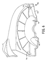
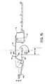
- the door 150 may be used with the dispenser 40 as shown in Figures 11-16.
- the door 150 may be formed integrally with the roll platform 46 or connected to the roll platform 46 using any suitable means, such as adhesives, welds, or mechanical fasteners.
- the door 150 pivotally opens by a living hinge 170, although other hinges may be used, such as a plurality of metal hinges, which permits the installing or viewing of the roll product 42.
- the door 150 forms an aperture 168 and a latch aperture 198, and includes a supporting means 176, a protruding member 188, and posts 172a-d forming respective post apertures 174a-d.
- the supporting means 176 includes a substantially circular hinge support 178 forming an aperture 180 that may be connected to the door 150 using any suitable means, such as welds, adhesives or mechanical fasteners.
- the support 178 includes four posts 182a-d (posts 182a and 182d not shown) formed integrally on the underside of the support 178, a protruding member 184, and a view shield member 160.
- the support 178 connects to the door 150 by inserting posts 182a-d into respective post apertures 174a-d.
- each support post 182a-d has a plurality of annular bulges 162a-d that seat within the annular grooves of the respective bores of the door posts 172a-d, locking the support posts 182a-d and door posts 172a-d together and thereby fastening the support 178 to the door 150.
- the support 178 may press against the undersides of the hinges 54a-k, thereby providing the hinges 54a-k added support for the weight of the roll product 42, which may relieve pressure from the buttresses 56a-k during dispensing.
- the view shield member 160 may be formed integrally with the underside of the support 178, and may prevent the viewing of the cavity 64 from underneath the dispenser 40 and debris from collecting between the hinge support 178 and the door 150.
- the shield member 160 is generally U-shaped, but other shapes may also be used.
- the protruding member 184 of the support 178 may extend in a first direction 186, which in this desired embodiment is substantially horizontal.
- the protruding member 188 of the door 150 may extend in a second direction 190, which in this desired embodiment is substantially horizontal and opposite of the first direction.
- These members 184 and 188 form a serpentine path 192 for a sheet of roll product 42 to travel from the roll product 42 to the user.
- roll products 42 have sheet materials that vary not only in composition, but also in the structure of perforations between individual sheets. This variance affects the tearing of the sheet material into individual segments.
- the support 178 and door 150 may be modified to vary a distance "A”, which is the overlapping region of the protruding members 184 and 188, and to vary a distance "B", which is the distance, in this embodiment a vertical distance, between protruding members 184 and 188. Changing these distances will alter the resistance of the sheet through the serpentine path 192 to accommodate the varying separation strengths of sheet material. For example, if the separation strength of the sheet is relatively strong, the distance "B" may be minimized and/or the distance "A" may be maximized.
- the distance "B” may be maximized and/or the distance "A” may be minimized. However, there are some considerations with regard to varying the distance "B". If the distance "B" is increased, the dispenser 40 size may be increased as well. If the distance "B” is minimized, it may become difficult to hand feed sheet material through the path 192 to begin dispensing, as described further hereinafter.
- the configuration of the door 150 and support 178 provide some advantages when separating individual segments of sheet material for use.
- the perforations tear simultaneously rather than sequentially. Simultaneous tearing minimizes rips in the body of the sheets outside of the perforations, which is particularly useful with sheets having a tendency to tear along the length of the sheet.
- this simultaneous tearing mechanism may be used with offset two-ply center feed rolls, which will be described in further detail hereinafter.
- Another advantage of this configuration is preventing the streaming or twisting of material dispensed from a newly inserted center feed roll product 42. The material is dispensed flat and smooth without twists and excess dispensing of sheets. This prevents waste of roll product 42 material.
- the latching assembly 82 may be coupled to the door 150 and operates the same as previously described. Desirably, the latching assembly 82 includes the latch 84, although the latch 84 is not shown in Figures 11-16.
- a roll product 42 in the dispenser 40 may begin operation. Pressing the base 112 may release the latch 84 from the catch 92 resulting in the door 150 pivoting open.
- the roll product 42 may be installed in a substantially upward direction, similarly as depicted in Figure 25, which will be described in further detail hereinafter.
- the roll product 42 is inserted into the dispenser 40 past the hinges 54a-k. Initially, when the roll product 42 contacts the hinges 54a-k, they may pivot upward permitting the roll product 42 to pass. Once the roll product 42 passes the hinges 54a-k, the hinges 54a-k may return to their dispensing position, which in this desirable embodiment is substantially horizontal. Afterwards, the roll product 42 may be set upon the hinges 54a-k.
- the buttresses 56a-k may aid in supporting the weight of the roll product 42. After inserting the roll product 42, it may be very difficult to remove, thereby deterring theft. Next, a sheet material portion 116 from the center of the roll product 42 may be unraveled and fed through the serpentine path 192 formed by the support 178 and door 150 to the exterior of the dispenser 40. Shutting the door 150 may permit operation of the dispenser 40.
- Pulling the sheet material perpendicular to the door 150 may feed material from the dispenser 40. If a segment of sheet material is desired, raising the material parallel to the door 150 and pulling may separate a segment.
- releasing the latch 192 may open the door 150. Looking upward into the opening 106 may permit verifying the amount of sheet material left on the roll product 42. If washing the dispenser 40 is desired, sheet material may be pulled toward the roll product 42 through the serpentine path 192 and positioned inside of the dispenser 40. Shutting the door 150 may permit vigorous washing of the dispenser 40, while minimizing the amount of water entering the cavity 64. The configuration of the door 150 and support 178, namely forming the serpentine path 192, may prevent water from reaching the roll product 42. After washing, the door 150 may be opened and the sheet material may be fed through the serpentine path 192 to the exterior of the dispenser 40. Closing the door 150 may permit dispensing to resume.
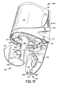
- the material dispenser includes a substantially L-shaped base 214, a cover 230, a supporting means 240, a door 234, and a latching assembly 260 as shown in Figure 17.
- the base 214 and cover 230 may be constructed from metal or plastic.
- the base 214 is constructed from polypropylene and the cover 230 is constructed from polystyrene, polypropylene, polyethylene, or other thermoplastics.
- the cover 230 may connect to the base 214 using any suitable means, such as adhesives, welds, or mechanical fasteners.
- the cover 230 may be adapted to loosely fit over or formed integrally with the base 214. Regardless of how the cover 230 is connected, the cover 230 and base 214 may form a cavity 232 for housing the center feed roll product 212.
- the cover 230 is constructed from a semi-transparent or translucent material permitting viewing of the roll product 212 within.
- the cover 230 may be constructed from an opaque material, and optionally, may surround a transparent material serving as a window.
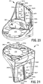
- the base 214 includes a roll platform 216, a securing means 222, and a mounting member 228 as shown in Figures 18-21.
- the roll platform 216 may be formed integrally with the mounting member 228.
- the roll platform 216 may be also formed integrally with a catch 268 of the latching assembly 260, which is described in further detail hereinafter.
- the mounting member 228 includes a plurality of mounting apertures 242a-I permitting attaching of the member 228 with mechanical fasteners to a support structure, such as a wall.
- the mounting member 228 may be fixed to a support structure using any suitable means such as adhesives or welds.
- the securing means 222 is formed integrally with the roll platform 216 as shown in Figures 19 and 20.
- the securing means 222 is connected to the roll platform 216 using any suitable means such as adhesives, welds, or mechanical fasteners.
- the securing means 222 desirably substantially circular, may form a substantially circular aperture 218, may be positioned inside of the roll platform 216, and may include at least one hinge 224f.
- eleven hinges 224a-k ring the substantially circular roll platform 216 and may be formed integrally with the roll platform 216 by a respective living hinge as shown in Figure 19. The length of the hinges 224a-k may be varied depending on the diameter size of the roll product 212.
- a respective buttress 226a-k may be mounted on the underside of each hinge 224a-k for reinforcement. Desirably, the hinges 224a-k only pivot upwardly from a substantially horizontal position, thereby allowing the insertion of the roll product 212 into the cavity 232, but not its removal. Alternatively, no buttresses 226a-k may be attached to the hinges 224a-k permitting the hinges 224a-k to pivot up or down from a substantially horizontal position.
- hinges 224a and 224k have respective tapered edges 272a and 272k that terminate forming respective tips 274a and 274k.
- the hinges 226a and 226k may form an opening 244.
- the opening 244 permits the removal of an operator's hand after installing the roll product 212 in the cavity 232.
- the opening 244 permits verifying the amount of sheet material on the roll product 212.
- the supporting means 240 includes a flap 250, a tab 254, a conical protrusion 252 forming an aperture 256, and an extension 258 as shown in Figure 17.
- the substantially circular flap 250 may be formed integrally with the conical protrusion 252, tab 254, and extension 258. Although one tab 254 is shown in this desired embodiment, a plurality of tabs 254 may be formed integrally with the flap 250.
- the flap 250 in this desired embodiment is substantially circular, it may be designed in other shapes as well.
- the conical protrusion 252 may terminate in a circular edge 276 for tearing sheet material, which is described in further detail hereinafter.
- the extension 258 may extend through an aperture 278 in the roll platform 216 and fasten thereto, thereby connecting the flap 250 with the roll platform 216.
- the flap 250 may be secured by bending the flap 250 at the extension 258 upward and twisting the flap 250 to clip the tab 254 onto the securing means 222.
- the flap 250 may press against the undersides of the hinges 224a-k, thereby desirably providing the hinges 224a-k added support for the weight of the roll product 212 and relieving pressure from the buttresses 226a-k during dispensing.
- the tab 254 may be undipped and the flap 250 may be removed from the securing means 222.
- the door 234 forming an aperture 236 may be formed integrally with the roll platform 216 or connected to the roll platform 216 using any suitable means, such as adhesives, welds, or mechanical fasteners.
- the door 234 may pivotally open by a living hinge 170, although other pivotal connectors may be used, such as separate metal hinges, which may permit the installing or viewing of the roll product 212.
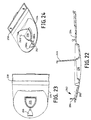
- the door 234 includes a sealing member 246 as shown in Figures 22 and 24.
- the sealing member 246 may be formed integrally with the door 234 by a hinge, although other pivotal connectors may be used.
- the latching assembly 260 includes a latch 262 and the catch 268 as shown in Figure 19 and Figures 22-24.
- the door 234 may form a latch aperture 266.
- the substantially L-shaped latch 262 may be pivotally secured at its convergence to the door 234 with a hinge and may include a base 282 formed integrally with a post 284, which may terminate forming protrusions 286a-b.
- the base 282 may reside within the latch aperture 266.
- the corresponding catch 268 may be formed integrally in the underside of the base 214 and form a slot 290. Shutting the door 234 inserts the post 284 into the slot 290 of the catch 268.
- the weight of the latch 262 may press the protrusions 286a-b against the interior of the catch 268, thereby maintaining the door 234 shut. Releasing the latch 262 by pressing the base 282 through the latch aperture 266 may pivot the post 284 freeing the protrusions 286a-b from the catch 268. Once the protrusions 286a-b are free of the catch 268, the door 234 may be opened permitting the placement or inspection of the roll product 212 within the dispenser 200.
- installing the roll product 212 in the dispenser 200 begins operation. Pressing the base 282 may release the latch 262 from the catch 268 resulting in the door 234 pivoting open. If the flap 250 is secured to the securing means 222, unclipping the tab 254 from the securing means 222 may release the flap 250, permitting the lowering of the flap 250.
- the roll product 212 may be installed in a substantially upward direction 280, with a single hand if desired, by an operator 296, as depicted in Figure 25. The roll product 212 may be inserted into the dispenser 200 past the hinges 224a-k. Initially, when the roll product 212 contacts the hinges 224a-k, they may pivot upward permitting the roll product 212 to pass.
- the hinges 224a-k may return to their dispensing position, which in this desirable embodiment is substantially horizontal. Afterwards, the roll product 212 may be set upon the hinges 224a-k. The buttresses 226a-k may aid in supporting the weight of the roll product 212. After inserting the roll product 212, it may not be removed, thereby deterring theft. Next, a material sheet portion 288 may be fed through the aperture 256 of the conical protrusion 252 past the flap 250. Afterwards, the sheet material portion 288 may be fed through the aperture 236 in the door 234. Shutting the flap 250 and door 234 may permit operation of the dispenser 200.
- Pulling the sheet material vertically downward may unravel portions of sheet material for use. Pulling the sheet material at an angle from vertical may result in friction between the sheet material and the conical protrusion edge 276. As a result, the sheet material may tear separating a portion for use.
- releasing the latch 262 may open the door 234. Looking upward into the opening 244 may permit verifying the amount of sheet material on the roll product 212.
- the sheet material may be pulled toward the roll product 212 through the apertures 236 and 256, and positioned inside of the dispenser 200.
- the sealing member 246 may be pivoted over the aperture 236.
- the flap 250 may be secured to the securing means 222 and the door 234 may be shut. Vigorous washing of the dispenser 200 may be conducted, while minimizing the amount of water entering the cavity 232.
- the door 234 may be opened, the sealing member 246 may be pivoted backward to its original position, and the sheet material may be fed through the apertures 256 and 236. Afterwards, the flap 250 may be pivoted upward and secured to the securing means 222. Closing the door 234 may permit dispensing to resume.
- the securing means and door are depicted in Figure 26.
- the securing means 322 includes a plurality of hinges 324 arranged in a substantially unbroken circular pattern.
- the door 334 forming an aperture 336 may include a sealing member 346.
- both the aperture 336 and sealing member 346 are substantially circular.
- cylindrical-shaped center feed roll products are used in presented embodiments of the invention.
- These roll products may have dimensions of width, which is a distance between the circular ends of the roll product, ranging from about 5 to about 245 millimeters and diameter, which is a straight line passing through a center of one of the circular ends of the roll product, ranging from about 150 to about 225 millimeters. More desirably, these roll products may have dimensions of width ranging from about 50 to about 245 millimeters. Even more desirable, these roll products may have dimensions of width of about 200 millimeters and diameter greater than about 200 millimeters to about 250 millimeters.
- one exemplary sheet material product is a center feed roll or barrel roll 400 illustrated in Figure 27.
- the roll 400 has been unwound slightly from its outer surface to show the offset perforation arrangement. It should be understood that in use, the webs will be fed out from the inner surface, and the webs on the outer surface will usually be secured to one another so that the roll 400 does not unwind as shown in the figure.
- the roll 400 includes an inner web 402 and an outer web 404 each having perforations 406, which may allow individual sheets 408 to be detached from the webs 402 and 404.
- the individual sheets 408 have a length X.
- the roll 400 is made from paper and is suitable for use as a hand towel or other wiper.
- the offset of the perforations 406 is shown as length Y, and in this desirable embodiment has an offset of 50/50.
- Figure 28 illustrates the roll 400 in use in a dispenser 410.
- the dispenser 410 is shown in outline only for simplicity of the figure.
- inner and outer webs 402 and 404 are fed through the aperture 412 of the dispenser 410, and due to the offset perforations 418, the sheet 414 of the inner web 402 protrudes from the dispenser 410 further than the sheet 416 of the outer web 404.
- the user may grip the sheet 414 and pull downwards until the friction force between the inner web 402 and the rim of the aperture 412 passes across perforations 418. Desirably, the sheet 414 will then detach leaving the end of the next sheet 420 of the inner web 402 at the aperture 412.
- the outer web 404 While the inner web 402 is being pulled, the outer web 404 is simultaneously moved downwards by virtue of it being wound with the inner web 402, and by the time the sheet 414 has become detached, the sheet 416 will be protruding from the dispenser 410 by a similar amount to the sheet 414 as shown in the diagram. Thus, the sheets are presented from alternate webs.
- Kimberly-Clark Europe standard test procedure number KCN-060 can be used to test the detaching strength of the line of perforations.
- This test uses an Instron Universal Testing Instrument to simulate a detaching action between two adjacent sheets of the perforated product. For a 200mm wide roll, the sheets are folded into thirds along the machine direction and placed in the 3 inch (76mm) jaws of the Instron instrument before the test is begun. The jaws initially have a gap of 102 ⁇ 2mm, and the top jaw is moved upwards at a constant rate of 250mm/min away from the bottom jaw until the perforations are broken. Total energy (kg/mm), peak load (g), percentage stretch at peak (%) and total stretch as a percentage (%) can be measured.
- the material tensile strength can also be measured in this way, using an unperforated sample, in the chosen direction (normally the machine direction). In practice a 50mm wide sample is tested, and the result multiplied by 4 to obtain the tensile strength for a 200mm wide roll.
Landscapes
- Health & Medical Sciences (AREA)
- Public Health (AREA)
- Closures For Containers (AREA)
- Details Of Rigid Or Semi-Rigid Containers (AREA)
- Unwinding Webs (AREA)
- Operating, Guiding And Securing Of Roll- Type Closing Members (AREA)
- Vending Machines For Individual Products (AREA)
- Seeds, Soups, And Other Foods (AREA)
- Basic Packing Technique (AREA)
- Containers And Plastic Fillers For Packaging (AREA)
Description
Claims (28)
- A dispenser (40;200) for a center feed roll (42;212) formed from at least one web, the dispenser comprising a housing having a base (44;214), wherein the base (44;214) includes a roll securing means (52;222;322) providing an aperture (48;218) through which the web may be dispensed from a roll (42;212), characterised in that said securing means (52;222;322) is configured to allow the insertion of a center feed roll (42;212) upwardly through the aperture (48;218) into the housing and to support the roll (42;212) during use so as to prevent withdrawal of the center feed roll (42;212) downwardly through the aperture (48;218) whilst permitting dispensing of web therethrough.
- The dispenser (40;200) of claim 1, wherein the base (44;214) includes a roll platform (46;216) coupled to the securing means (52;222;322), and wherein said housing includes a cover (62;230) adapted to fit the base (44;214) and defining a cavity (64;232) to receive the center feed roll (42;212).
- The roll dispenser (40;200) of claim 2, further comprising a mounting member (58;228) coupled to the roll platform (46;216).
- The roll dispenser (40;200) of any preceding claim, wherein the securing means (52;222;322) comprises a hinge (54a-k;224a-k) which pivots inward into the housing permitting placement of the roll (42;212) within the dispenser and returns to a dispensing position to secure the roll for dispensing.
- The roll dispenser (40;200) of claim 4, wherein the securing means (52;222) further comprises at least one buttress (56a-k;226a-k) coupled to the hinge (54a-k;224a-k) to prevent the hinge from pivoting past the dispensing position.
- The roll dispenser (40;200) of any preceding claim, the dispenser further comprising a supporting means (72;240) bracing the securing means (52;222;322).
- The roll dispenser (40;200) of claim 6, wherein the supporting means (240) is a flap (250) comprising a protrusion (252) and a tab (254) coupled to the base (214).
- The roll dispenser (40;200) of any preceding claim, the dispenser further comprising a door (66;150;234;334) defining an aperture (68;168;236;336) coupled to the base (44;214) by a hinge (170).
- The roll dispenser (40;200) of claim 8, wherein the door (66;234;334) comprises a sealing member (78;94;246;346) coupled to the door and a latching assembly (82;262) coupling the door to the base (44;214).
- The roll dispenser (40;200) of claim 9, wherein the sealing member (78;94;246;346) is positionable to substantially seal the door aperture (68;236;336) for preventing liquids from entering the dispenser.
- The roll dispenser (40;200) of any of claims 1 to 7, the dispenser further comprising a door (66;150;234;334) defining an aperture (68;168;236;336) coupled to the base (44;214).
- The roll dispenser (40;200) of claim 11, wherein the door (66) comprises a supporting means (72) comprising a hinge support (74) coupled to the door, an aperture disc (76) coupled to the door and surrounding the door aperture (68) to aid the tearing of roll products (42) and a sealing member (78).
- The roll dispenser (40;200) of claim 12, the dispenser further comprising a latching assembly (82;262) coupling the door (66;234;334) to the base (44;214) so that the latching assembly supports the weight of the roll product (42;212) inside of the dispenser.
- The roll dispenser (40;200) of claim 12 or 13, wherein the aperture disc (76) is constructed from an elastomeric material.
- The roll dispenser (40;200) of claim 11, wherein the door (150) comprises a supporting means (176) coupled to the door wherein the supporting means further comprises a protruding member (184) extending in a first direction (186), and a protruding member (188) coupled to the door and positioned in the aperture of the door (168) and extending in a second direction (190) substantially opposite of the first direction whereby a roll product (42) withdrawn form the dispenser follows a serpentine path (192) around the protruding members (184,188).
- The roll dispenser (40;200) of any preceding claim, wherein the housing includes a cover (62;230) constructed from a semi-transparent material for viewing the roll product (42;212) within.
- The roll dispenser (40;200) of any of claims 1 to 15, wherein the housing includes a cover (62;230) constructed from an opaque material forming a window for viewing the roll product (42;212) within.
- The dispenser (40) of claim 1, wherein the base (44) comprises a mounting member (58) and a roll platform (46), wherein the mounting member and securing means (52) are coupled to the roll platform, and wherein said housing includes a cover (62) adapted to fit the base wherein the cover is constructed from a semi-transparent material for viewing the roll product (42) within, the dispenser further comprising a door (150) defining an aperture (168) pivotally coupled to the base wherein the door further comprises a supporting means (176) coupled to the door wherein the supporting means further comprises a protruding member (184) extending in a first direction (186), and a protruding member (188) coupled to the door and positioned in the aperture of the door and extending in a direction (190) substantially opposite of the first direction whereby a roll product withdrawn from the dispenser follows a serpentine path (192) around the protruding members (184,188), and a latching assembly (82) coupling the door to the base so that the latching assembly supports the weight of the roll product inside of the dispenser.
- The dispenser (40) of claim 1, wherein said means (52) is a base (44) comprising a mounting member (58) and a roll platform (46), wherein the mounting member and the securing means (52) are coupled to the roll platform, the securing means comprising a substantially circular member having a plurality of hinges (54a-k) which pivot substantially upward permitting the placement of the roll product (42) within the dispenser and return substantially horizontal for securing the roll product, wherein the housing includes a cover (62) adapted to fit the base (44) wherein the cover is constructed from a semi-transparent material for viewing the roll product within wherein the cover and the base are sized to receive roll products having a diameter between about 150 millimeters to about 225 millimeters and a width between about 5 millimeters to about 245 millimeters, the dispenser further comprising a door (150) defining an aperture (168) pivotally coupled to the base wherein the door further comprises a supporting means (176) coupled to the door wherein the supporting means further comprises a protruding member (184) extending in a first direction (186), and a protruding member (188) coupled to the door and positioned in the aperture of the door and extending in a second direction (190) substantially opposite of the first direction whereby a roll product withdrawn from the dispenser follows a serpentine path (192) around the protruding members (184,188), and a latching assembly (82) coupling the door to the base so that the latching assembly supports the weight of the roll product inside of the dispenser.
- The dispenser (40;200) for center feed roll products (42;212) of any preceding claim configured to receive the roll products having a width from about 180 millimeters to about 245 millimeters.
- The dispenser (40;200) of claim 1, wherein the securing means (52;222;322) comprises a plurality of cantilevered hinges (54a-k;224a-k;324), the hinges extending radially inward toward the center of the securing means and defining said aperture (48;218).
- The dispenser (40;200) of claim 21, wherein the hinges (54a-k;224a-k;324) pivot inward from a first position into the housing enabling placement of the center feed roll (42;212) product therein, whereupon the hinges return to the first position to support the weight of the center feed roll product thereon.
- The dispenser (40;200) of claim 22, further comprising a door (66; 150;234;334) having an aperture (68;168;236;336) therethrough, the door being fastened to the base (44;214), the aperture in the door aligning with the aperture formed by the cantilevered hinges (54a-k;224a-k;324) to enable dispensing of a length of the center feed roll product (42;212).
- The dispenser (40;200) of claim 23, wherein the door (66; 150:234:334) further comprises a hinge support (74;178) for contacting and supporting the plurality of cantilevered hinges (54a-k;224a-k).
- The dispenser (40;200) of claim 24, further comprising a positionable sealing member (78;94;246;346) for selectively sealing the aperture (68;168;236;336) in the door (66;150;234;334) from liquid intrusion or enabling dispensing of the length of the center feed roll product (42;212).
- The dispenser (40;200) of claim 1, wherein at least a portion of the securing means (52;222;322) pivots inward from a first position toward the housing enabling placement of the center feed roll product (42;212) therein, whereupon the portion of the securing means returns to the first position to support the weight of the center feed roll product thereon.
- The dispenser (40;200) of claim 26, further comprising a door (66;150;234;334) having an aperture (68;168;236;336) therethrough, the door being fastened to the base (44;214), the aperture in the door aligning with the aperture in the securing means (52;222;322) to enable dispensing of the center feed roll product (42;212).
- The dispenser (40;200) of claim 27, further comprising a positionable sealing member (78;94;246;346) for selectively sealing the aperture (68;168;236;336) in the door (66;150;234;334) from liquid intrusion or enabling dispensing of the length of the center feed roll product (42;212).
Applications Claiming Priority (5)
| Application Number | Priority Date | Filing Date | Title |
|---|---|---|---|
| US6168397P | 1997-10-10 | 1997-10-10 | |
| US61683P | 1997-10-10 | ||
| US09/113,858 US6145782A (en) | 1997-10-10 | 1998-07-10 | Sheet material dispenser |
| US113858 | 1998-07-10 | ||
| PCT/GB1998/003061 WO1999018835A1 (en) | 1997-10-10 | 1998-10-12 | Sheet material dispenser |
Publications (2)
| Publication Number | Publication Date |
|---|---|
| EP1021118A1 EP1021118A1 (en) | 2000-07-26 |
| EP1021118B1 true EP1021118B1 (en) | 2004-03-03 |
Family
ID=26741370
Family Applications (1)
| Application Number | Title | Priority Date | Filing Date |
|---|---|---|---|
| EP98946621A Expired - Lifetime EP1021118B1 (en) | 1997-10-10 | 1998-10-12 | Sheet material dispenser |
Country Status (10)
| Country | Link |
|---|---|
| US (1) | US6145782A (en) |
| EP (1) | EP1021118B1 (en) |
| JP (1) | JP2001519188A (en) |
| AR (1) | AR017313A1 (en) |
| AU (1) | AU743442B2 (en) |
| CA (1) | CA2304580C (en) |
| DE (1) | DE69822181T2 (en) |
| ES (1) | ES2215321T3 (en) |
| MY (1) | MY133007A (en) |
| WO (1) | WO1999018835A1 (en) |
Families Citing this family (67)
| Publication number | Priority date | Publication date | Assignee | Title |
|---|---|---|---|---|
| EP1066787B1 (en) * | 1999-07-08 | 2005-03-09 | Georgia-Pacific France | Paperweb roll dispenser with centre feeding out |
| USD449474S1 (en) | 2000-04-05 | 2001-10-23 | Georgia-Pacific France | Paper roll dispenser |
| US6510964B2 (en) * | 2000-11-13 | 2003-01-28 | Englewood Ventures, Inc. | Center-pull sheet material dispenser |
| USD467106S1 (en) | 2001-03-23 | 2002-12-17 | Larry J Bohay | Toilet tissue roll container |
| US7275672B2 (en) | 2001-09-11 | 2007-10-02 | Alwin Manufacturing Company, Inc. | Center pull dispenser with self-adjusting dispenser mechanism |
| US6592002B2 (en) | 2001-10-29 | 2003-07-15 | Kimberly-Clark Worldwide, Inc. | Dispenser for dispensing a stack of folded sheet products |
| US6592001B2 (en) | 2001-12-18 | 2003-07-15 | Kimberly-Clark Worldwide | Dispenser for sheet material containing a dispensing port incrementally variable within a range |
| US6629667B2 (en) * | 2001-12-28 | 2003-10-07 | Kimberly-Clark Corporation | Dispenser for sheet material |
| US20030215602A1 (en) * | 2002-02-26 | 2003-11-20 | Anders Andersson | Method and device for producing a multi-ply web of flexible material, such as paper and nonwoven, and multi-ply material and product produced by the method |
| US6575397B1 (en) * | 2002-04-25 | 2003-06-10 | Kimberly-Clark Worldwide, Inc. | Dispenser for sheet material |
| US6779683B2 (en) | 2002-04-30 | 2004-08-24 | Kimberly-Clark Worldwide, Inc. | Dispenser for dispensing sheet material |
| US6910579B2 (en) * | 2002-05-28 | 2005-06-28 | Georgia-Pacific Corporation | Refillable flexible sheet dispenser |
| US7216775B2 (en) * | 2003-03-12 | 2007-05-15 | Union Street Brand Packaging | Moist towelette packaging |
| USD488655S1 (en) | 2003-04-04 | 2004-04-20 | Kimberly-Clark Worldwide | Dispenser for absorbent paper products |
| US6959885B2 (en) * | 2003-09-30 | 2005-11-01 | Kimberly-Clark Worldwide, Inc. | Center-feed roll and method of making thereof |
| US7040568B2 (en) * | 2004-04-02 | 2006-05-09 | Kimberly-Clark Worldwide, Inc. | Dispenser for sheet material |
| US6964395B1 (en) | 2004-06-30 | 2005-11-15 | Kimberly-Clark Worldwide, Inc. | Dispenser for rolled sheet material |
| US7530460B2 (en) * | 2004-06-30 | 2009-05-12 | Kimberly-Clark Worldwide, Inc. | Dispenser for rolled sheet material |
| USD522785S1 (en) * | 2005-01-31 | 2006-06-13 | James Brady | Towel dispenser |
| US7806291B2 (en) * | 2005-05-19 | 2010-10-05 | Buckeye Technologies | Center-pull dispenser for web material |
| US7703621B2 (en) * | 2005-08-25 | 2010-04-27 | Union Street Brand Packaging Llc | Moisture retention seal |
| FR2893495B1 (en) * | 2005-11-18 | 2008-02-15 | Georgia Pacific France Soc En | PAPER DISPENSER |
| FR2907654B1 (en) | 2006-10-31 | 2010-01-29 | Georgia Pacific France | PROCESS, MANUFACTURING DEVICE AND ASSOCIATED ROLLS FORMED OF CUTTING SHEETS AND ALTERNATE PREDECOUPLES |
| US11297984B2 (en) | 2006-10-31 | 2022-04-12 | Gpcp Ip Holdings Llc | Automatic napkin dispenser |
| US7510137B2 (en) | 2007-05-24 | 2009-03-31 | Kimberly-Clark Worldwide, Inc. | Dispenser for sheet material |
| US7997443B2 (en) * | 2007-11-13 | 2011-08-16 | Cintas Corporation | Center-pull paper towel dispenser |
| US7997522B2 (en) * | 2007-11-13 | 2011-08-16 | Cintas Corporation | Center-pull paper towel dispenser |
| USD634142S1 (en) * | 2008-04-24 | 2011-03-15 | Sca Hygiene Products Ab | Soap dispenser |
| CN102026788A (en) | 2008-05-16 | 2011-04-20 | Sca卫生用品公司 | Method of making a dispenser or a part thereof and a dispenser or part made by said method |
| WO2009138453A1 (en) | 2008-05-16 | 2009-11-19 | Sca Hygiene Products Ab | Two-component injection moulded dispenser part |
| DE102009015855B4 (en) * | 2009-04-01 | 2013-01-17 | Sprick Gmbh Bielefelder Papier- Und Wellpappenwerke & Co. | Protective cover for positioning at an exit opening of a device for providing packaging material and a device with such a protective cover |
| USD623453S1 (en) * | 2009-06-30 | 2010-09-14 | Sca Hygiene Products Ab | Center pull dispenser |
| US9908691B2 (en) * | 2010-06-30 | 2018-03-06 | Gpcp Ip Holdings Llc | Dispenser and sheet product dispensing plate therefor |
| US20120097697A1 (en) * | 2010-10-25 | 2012-04-26 | Debra Gay Gehring | Wipes product |
| ES2659726T3 (en) | 2011-10-21 | 2018-03-19 | Sca Tissue France | Dispenser for static roll without core of central feeding of sheet product |
| US9113760B2 (en) * | 2011-12-06 | 2015-08-25 | Alwin Manufacturing Co., Inc. | Low-material-indicating center pull dispenser |
| WO2013085493A1 (en) * | 2011-12-06 | 2013-06-13 | Alwin Manufacturing Co., Inc. | Low-material-indicating center pull dispenser |
| US10383489B2 (en) | 2012-02-10 | 2019-08-20 | Gpcp Ip Holdings Llc | Automatic napkin dispenser |
| US9101250B2 (en) | 2012-05-21 | 2015-08-11 | Gojo Industries, Inc. | Wipes dispenser nozzle |
| FR3010621B1 (en) * | 2013-09-19 | 2015-12-25 | Maurice Granger | APPARATUS FOR DISPENSING BANDS OF PRE-COATED ROLLED MATERIAL IN HORIZONTAL OR VERTICAL POSITIONED COIL |
| US9604811B2 (en) | 2013-10-01 | 2017-03-28 | Georgia-Pacific Consumer Products Lp | Automatic paper product dispenser with data collection and method |
| GB2536144A (en) * | 2013-11-18 | 2016-09-07 | Ipek Kagit Sanayi Ve Ticaret Anonim Sirketi | A dispenser comprising a system facilitating the placement of the product made of paper into the dispenser |
| DE102014006220B4 (en) * | 2014-04-30 | 2015-12-31 | Metsä Tissue Oyj | Output device for flat products with a holding means arranged in an interior |
| WO2016018202A1 (en) * | 2014-07-28 | 2016-02-04 | Bemis Company, Inc. | Bottom dispensing wet wipe container |
| US10016099B2 (en) | 2014-11-13 | 2018-07-10 | Gpcp Ip Holdings Llc | Sheet product dispensers and related methods for protecting a roll of sheet product and reducing waste |
| USD771968S1 (en) | 2015-01-21 | 2016-11-22 | Cintas Corporation | Dispenser |
| FR3032341B1 (en) * | 2015-02-06 | 2017-10-27 | Maurice Granger | DISTRIBUTOR APPARATUS FOR BANDS OF HORIZONTAL OR VERTICAL POSITIONED COIL FLEXIBLE MATERIAL |
| GB2538235B (en) * | 2015-05-10 | 2017-05-10 | John Gordon Michael | Container of wipes with 'Fallback Prevent'dispensing nozzle |
| USD775853S1 (en) | 2015-07-21 | 2017-01-10 | Cintas Corporation | Soap dispenser |
| GB2544828B (en) * | 2016-04-01 | 2018-02-28 | Yeo Oliver | A protective barrier dispenser for providing hygienic protection of hands when using a service station forecourt fuel pump |
| US10292545B2 (en) * | 2016-11-18 | 2019-05-21 | RD Textiles, LLC | Center-pull dispenser system |
| CN110494070A (en) | 2017-05-10 | 2019-11-22 | Gpcp知识产权控股有限责任公司 | Automatic paper product dispenser and associated method |
| US10849470B2 (en) | 2017-12-15 | 2020-12-01 | Gojo Industries, Inc. | Wipes dispensers and easy load adjustable dispensing nozzle |
| US20190208966A1 (en) * | 2018-01-05 | 2019-07-11 | San Jamar, Inc. | Collapsible dispenser system |
| USD916960S1 (en) * | 2019-02-19 | 2021-04-20 | Kinnos Inc. | Applicator for wipes |
| US10898037B2 (en) * | 2019-03-06 | 2021-01-26 | Alexei Fomine | Dispenser and cleaning assembly |
| US11419462B2 (en) * | 2019-03-07 | 2022-08-23 | Gojo Industries, Inc. | Wipes dispensing nozzles having wear indicators and wipes dispensers having the same |
| US11224314B2 (en) | 2019-05-31 | 2022-01-18 | San Jamar, Inc. | Web material center-pull dispenser assembly |
| USD984824S1 (en) | 2019-05-31 | 2023-05-02 | San Jamar, Inc. | Center pull-through dispenser |
| PL3818918T3 (en) * | 2019-11-08 | 2024-05-13 | Essity Hygiene And Health Aktiebolag | Dispenser for a roll of absorbent paper web material |
| US20210386253A1 (en) * | 2020-06-10 | 2021-12-16 | Dispensing Dynamics International, Inc. | Wipes dispenser |
| USD995140S1 (en) | 2020-06-22 | 2023-08-15 | Kimberly-Clark Worldwide, Inc. | Paper product dispenser |
| AU2020455329A1 (en) * | 2020-06-22 | 2023-02-16 | Kimberly-Clark Worldwide, Inc. | Dispenser for rolled sheet material |
| USD968217S1 (en) | 2020-09-30 | 2022-11-01 | Metrex Research, LLC | Container lid |
| USD967706S1 (en) | 2020-09-30 | 2022-10-25 | Metrex Research, LLC | Container lid |
| JP7529583B2 (en) * | 2021-02-08 | 2024-08-06 | 大王製紙株式会社 | Fixture for sanitary tissue paper storage container |
| US20230011566A1 (en) * | 2021-07-12 | 2023-01-12 | Robert Butt | Disinfectant Wet Wash Dispenser Device |
Family Cites Families (25)
| Publication number | Priority date | Publication date | Assignee | Title |
|---|---|---|---|---|
| US2033582A (en) * | 1933-02-04 | 1936-03-10 | Materno Arthur | Dispensing container for toilet paper |
| US2948486A (en) * | 1958-09-29 | 1960-08-09 | Leon A Epeneter | Dispensing holder for rolled material |
| US3150808A (en) * | 1960-12-05 | 1964-09-29 | Richard R Vensel | Dispenser for rolled paper and paper roll therefor |
| GB956621A (en) * | 1961-01-26 | 1964-04-29 | Steiner Co Lausanne Sa | Sheet material dispensing device |
| US3523653A (en) * | 1967-11-29 | 1970-08-11 | Raymond Lee Organization Inc | Paper holder |
| US3581935A (en) * | 1968-05-14 | 1971-06-01 | William I Andress | Process for folding sheet material and packaged dispensers therefor |
| US3749296A (en) * | 1972-07-10 | 1973-07-31 | Sterling Drug Inc | Exit slit for bulk package moist towels or tissues |
| US4009682A (en) * | 1976-04-19 | 1977-03-01 | Central Soya Company, Inc. | Web dispenser |
| ZA791006B (en) * | 1978-03-07 | 1980-03-26 | Finkelstein Oscar | Dispenser for web-like material |
| EP0107487A1 (en) * | 1982-10-20 | 1984-05-02 | Bowater-Scott Corporation Limited | Improvements in sheet material dispensers |
| SE445033B (en) * | 1984-10-12 | 1986-05-26 | Moelnlycke Ab | dispensing device |
| IT1234533B (en) * | 1988-03-03 | 1992-05-20 | Fabrizio Bernacchi | METHOD INCLUDING THE MANUFACTURE AND DISTRIBUTION OF ROLLS OF MATERIAL IN TAPES THAT ALLOWS TO HAVE THE DELIVERY OF THEM, FROM A SPECIAL DISTRIBUTOR IN SINGLE SHEETS AND OF PREDETERMINED DIMENSIONS |
| US5152121A (en) * | 1988-10-15 | 1992-10-06 | Kennak U.S.A. Inc. | Dispenser-container for wet tissues, and a process for manufacturing the same and an apparatus therefor |
| US4963406A (en) * | 1988-10-20 | 1990-10-16 | James River Corporation Of Virginia | Absorbent paper towel or tissue product |
| CA2044188C (en) * | 1990-06-28 | 2002-02-12 | Richard P. Lewis | Variable orifice centerflow dispenser |
| FR2667853B1 (en) * | 1990-10-12 | 1993-08-06 | Granger Maurice | PAPER TOWEL DISPENSER WITH CENTRAL WINDING. |
| FR2668694B1 (en) * | 1990-11-06 | 1993-01-22 | Maurice Granger | WIPER MATERIAL DISPENSER WITH CENTRAL WINDING. |
| US5205454A (en) * | 1992-05-18 | 1993-04-27 | James River Ii, Inc. | Paper towel dispensing system |
| USD342635S (en) | 1992-07-20 | 1993-12-28 | Robert E. Blazier | Moistened towelette dispenser |
| US5332118A (en) * | 1993-08-17 | 1994-07-26 | The Procter & Gamble Company | Pop-up towel dispensing system |
| GB9512835D0 (en) * | 1995-06-23 | 1995-08-23 | Morand Michael | Paper towel dispenser for dispensing paper towels from inside diameter of coreless roll |
| GB2308114B (en) * | 1995-12-14 | 1999-09-29 | Kimberly Clark Ltd | Centre-feed roll |
| USD385734S (en) | 1996-09-25 | 1997-11-04 | James River Corporation Of Virginia | Center pull towel dispenser |
| US5765718A (en) * | 1996-10-16 | 1998-06-16 | Fort James Corporation | Center pull sheet dispensing apparatus |
| USD406974S (en) | 1997-10-10 | 1999-03-23 | Kimberly-Clark Worldwide, Inc. | Sheet material dispenser |
-
1998
- 1998-07-10 US US09/113,858 patent/US6145782A/en not_active Expired - Lifetime
- 1998-10-06 MY MYPI98004564A patent/MY133007A/en unknown
- 1998-10-08 AR ARP980105031A patent/AR017313A1/en not_active Application Discontinuation
- 1998-10-12 WO PCT/GB1998/003061 patent/WO1999018835A1/en not_active Ceased
- 1998-10-12 ES ES98946621T patent/ES2215321T3/en not_active Expired - Lifetime
- 1998-10-12 JP JP2000515478A patent/JP2001519188A/en active Pending
- 1998-10-12 DE DE69822181T patent/DE69822181T2/en not_active Expired - Fee Related
- 1998-10-12 CA CA002304580A patent/CA2304580C/en not_active Expired - Fee Related
- 1998-10-12 AU AU93616/98A patent/AU743442B2/en not_active Ceased
- 1998-10-12 EP EP98946621A patent/EP1021118B1/en not_active Expired - Lifetime
Also Published As
| Publication number | Publication date |
|---|---|
| AR017313A1 (en) | 2001-09-05 |
| US6145782A (en) | 2000-11-14 |
| CA2304580A1 (en) | 1999-04-22 |
| HK1027949A1 (en) | 2001-02-02 |
| MY133007A (en) | 2007-10-31 |
| DE69822181D1 (en) | 2004-04-08 |
| WO1999018835A1 (en) | 1999-04-22 |
| AU9361698A (en) | 1999-05-03 |
| CA2304580C (en) | 2008-06-03 |
| EP1021118A1 (en) | 2000-07-26 |
| JP2001519188A (en) | 2001-10-23 |
| DE69822181T2 (en) | 2004-07-29 |
| AU743442B2 (en) | 2002-01-24 |
| ES2215321T3 (en) | 2004-10-01 |
Similar Documents
| Publication | Publication Date | Title |
|---|---|---|
| CA2304580C (en) | Sheet material dispenser | |
| EP1465517B1 (en) | Dispenser for sheet material | |
| US6575397B1 (en) | Dispenser for sheet material | |
| US7131609B1 (en) | Dispenser for sheet material | |
| US5765718A (en) | Center pull sheet dispensing apparatus | |
| US6959891B2 (en) | Dispenser for multiple rolls of sheet material | |
| US20030111480A1 (en) | Dispenser for sheet material containing a dispensing port incrementally variable within a range | |
| US7040567B1 (en) | Dispenser for perforated sheet material providing flat sheet delivery | |
| GB2120639A (en) | Dispenser for web material | |
| MX2013003948A (en) | Stack of tissue paper and distribution therefor. | |
| WO2005102129A1 (en) | Dispenser for sheet material | |
| HK1027949B (en) | Sheet material dispenser | |
| EP0089933B1 (en) | Rolled paper dispenser | |
| WO2006007186A1 (en) | Dispenser for rolled sheet material | |
| MXPA00003521A (en) | Sheet material dispenser | |
| TW436275B (en) | A dispenser for center feed roll products | |
| KR20070023791A (en) | Splitter for roll sheet material |
Legal Events
| Date | Code | Title | Description |
|---|---|---|---|
| PUAI | Public reference made under article 153(3) epc to a published international application that has entered the european phase |
Free format text: ORIGINAL CODE: 0009012 |
|
| 17P | Request for examination filed |
Effective date: 20000420 |
|
| AK | Designated contracting states |
Kind code of ref document: A1 Designated state(s): BE DE ES FR GB IT NL SE |
|
| 17Q | First examination report despatched |
Effective date: 20030121 |
|
| GRAP | Despatch of communication of intention to grant a patent |
Free format text: ORIGINAL CODE: EPIDOSNIGR1 |
|
| GRAS | Grant fee paid |
Free format text: ORIGINAL CODE: EPIDOSNIGR3 |
|
| GRAA | (expected) grant |
Free format text: ORIGINAL CODE: 0009210 |
|
| AK | Designated contracting states |
Kind code of ref document: B1 Designated state(s): BE DE ES FR GB IT NL SE |
|
| REG | Reference to a national code |
Ref country code: GB Ref legal event code: FG4D |
|
| BECA | Be: change of holder's address |
Owner name: *KIMBERLY-CLARK LTD1 TOWER VIEW, KINGS HILL, WEST Effective date: 20040303 |
|
| REF | Corresponds to: |
Ref document number: 69822181 Country of ref document: DE Date of ref document: 20040408 Kind code of ref document: P |
|
| RAP2 | Party data changed (patent owner data changed or rights of a patent transferred) |
Owner name: KIMBERLY-CLARK LIMITED |
|
| REG | Reference to a national code |
Ref country code: SE Ref legal event code: TRGR |
|
| NLT2 | Nl: modifications (of names), taken from the european patent patent bulletin |
Owner name: KIMBERLY-CLARK LIMITED |
|
| PGFP | Annual fee paid to national office [announced via postgrant information from national office to epo] |
Ref country code: BE Payment date: 20040908 Year of fee payment: 7 |
|
| REG | Reference to a national code |
Ref country code: ES Ref legal event code: FG2A Ref document number: 2215321 Country of ref document: ES Kind code of ref document: T3 |
|
| PGFP | Annual fee paid to national office [announced via postgrant information from national office to epo] |
Ref country code: NL Payment date: 20041025 Year of fee payment: 7 |
|
| ET | Fr: translation filed | ||
| REG | Reference to a national code |
Ref country code: HK Ref legal event code: GR Ref document number: 1027949 Country of ref document: HK |
|
| PLBE | No opposition filed within time limit |
Free format text: ORIGINAL CODE: 0009261 |
|
| STAA | Information on the status of an ep patent application or granted ep patent |
Free format text: STATUS: NO OPPOSITION FILED WITHIN TIME LIMIT |
|
| 26N | No opposition filed |
Effective date: 20041206 |
|
| PG25 | Lapsed in a contracting state [announced via postgrant information from national office to epo] |
Ref country code: BE Free format text: LAPSE BECAUSE OF NON-PAYMENT OF DUE FEES Effective date: 20051031 |
|
| PG25 | Lapsed in a contracting state [announced via postgrant information from national office to epo] |
Ref country code: NL Free format text: LAPSE BECAUSE OF NON-PAYMENT OF DUE FEES Effective date: 20060501 |
|
| NLV4 | Nl: lapsed or anulled due to non-payment of the annual fee |
Effective date: 20060501 |
|
| BERE | Be: lapsed |
Owner name: *KIMBERLY-CLARK LTD Effective date: 20051031 |
|
| PGFP | Annual fee paid to national office [announced via postgrant information from national office to epo] |
Ref country code: DE Payment date: 20081201 Year of fee payment: 11 |
|
| PGFP | Annual fee paid to national office [announced via postgrant information from national office to epo] |
Ref country code: ES Payment date: 20081027 Year of fee payment: 11 |
|
| PGFP | Annual fee paid to national office [announced via postgrant information from national office to epo] |
Ref country code: SE Payment date: 20081029 Year of fee payment: 11 Ref country code: IT Payment date: 20081029 Year of fee payment: 11 |
|
| PGFP | Annual fee paid to national office [announced via postgrant information from national office to epo] |
Ref country code: FR Payment date: 20081018 Year of fee payment: 11 |
|
| PGFP | Annual fee paid to national office [announced via postgrant information from national office to epo] |
Ref country code: GB Payment date: 20081029 Year of fee payment: 11 |
|
| EUG | Se: european patent has lapsed | ||
| REG | Reference to a national code |
Ref country code: FR Ref legal event code: ST Effective date: 20100630 |
|
| PG25 | Lapsed in a contracting state [announced via postgrant information from national office to epo] |
Ref country code: FR Free format text: LAPSE BECAUSE OF NON-PAYMENT OF DUE FEES Effective date: 20091102 Ref country code: DE Free format text: LAPSE BECAUSE OF NON-PAYMENT OF DUE FEES Effective date: 20100501 |
|
| PG25 | Lapsed in a contracting state [announced via postgrant information from national office to epo] |
Ref country code: GB Free format text: LAPSE BECAUSE OF NON-PAYMENT OF DUE FEES Effective date: 20091012 |
|
| PG25 | Lapsed in a contracting state [announced via postgrant information from national office to epo] |
Ref country code: IT Free format text: LAPSE BECAUSE OF NON-PAYMENT OF DUE FEES Effective date: 20091012 |
|
| REG | Reference to a national code |
Ref country code: ES Ref legal event code: FD2A Effective date: 20110411 |
|
| PG25 | Lapsed in a contracting state [announced via postgrant information from national office to epo] |
Ref country code: SE Free format text: LAPSE BECAUSE OF NON-PAYMENT OF DUE FEES Effective date: 20091013 |
|
| PG25 | Lapsed in a contracting state [announced via postgrant information from national office to epo] |
Ref country code: ES Free format text: LAPSE BECAUSE OF NON-PAYMENT OF DUE FEES Effective date: 20110329 |
|
| PG25 | Lapsed in a contracting state [announced via postgrant information from national office to epo] |
Ref country code: ES Free format text: LAPSE BECAUSE OF NON-PAYMENT OF DUE FEES Effective date: 20091013 |