EP1021016A1 - Dispositif de descrimination de défauts dans une liaison louée numérique - Google Patents
Dispositif de descrimination de défauts dans une liaison louée numérique Download PDFInfo
- Publication number
- EP1021016A1 EP1021016A1 EP00400024A EP00400024A EP1021016A1 EP 1021016 A1 EP1021016 A1 EP 1021016A1 EP 00400024 A EP00400024 A EP 00400024A EP 00400024 A EP00400024 A EP 00400024A EP 1021016 A1 EP1021016 A1 EP 1021016A1
- Authority
- EP
- European Patent Office
- Prior art keywords
- signal
- equipment
- ettda
- transmitted
- etcda
- Prior art date
- Legal status (The legal status is an assumption and is not a legal conclusion. Google has not performed a legal analysis and makes no representation as to the accuracy of the status listed.)
- Granted
Links
- 230000005540 biological transmission Effects 0.000 claims description 23
- 238000012545 processing Methods 0.000 claims description 9
- 108010076504 Protein Sorting Signals Proteins 0.000 claims description 7
- 230000007257 malfunction Effects 0.000 claims description 6
- 230000001419 dependent effect Effects 0.000 claims 2
- 238000012360 testing method Methods 0.000 description 10
- 230000002457 bidirectional effect Effects 0.000 description 3
- 238000012544 monitoring process Methods 0.000 description 3
- 230000004913 activation Effects 0.000 description 2
- 230000007547 defect Effects 0.000 description 2
- 238000001514 detection method Methods 0.000 description 2
- 238000010586 diagram Methods 0.000 description 2
- 238000012423 maintenance Methods 0.000 description 2
- 239000013307 optical fiber Substances 0.000 description 2
- 230000001360 synchronised effect Effects 0.000 description 2
- 238000012550 audit Methods 0.000 description 1
- 230000002950 deficient Effects 0.000 description 1
- 230000001934 delay Effects 0.000 description 1
- 230000007274 generation of a signal involved in cell-cell signaling Effects 0.000 description 1
- 238000003780 insertion Methods 0.000 description 1
- 230000037431 insertion Effects 0.000 description 1
- 238000009434 installation Methods 0.000 description 1
- 238000007726 management method Methods 0.000 description 1
- 238000000034 method Methods 0.000 description 1
- 230000008054 signal transmission Effects 0.000 description 1
Images

Classifications
-
- H—ELECTRICITY
- H04—ELECTRIC COMMUNICATION TECHNIQUE
- H04L—TRANSMISSION OF DIGITAL INFORMATION, e.g. TELEGRAPHIC COMMUNICATION
- H04L43/00—Arrangements for monitoring or testing data switching networks
- H04L43/08—Monitoring or testing based on specific metrics, e.g. QoS, energy consumption or environmental parameters
- H04L43/0805—Monitoring or testing based on specific metrics, e.g. QoS, energy consumption or environmental parameters by checking availability
- H04L43/0817—Monitoring or testing based on specific metrics, e.g. QoS, energy consumption or environmental parameters by checking availability by checking functioning
-
- H—ELECTRICITY
- H04—ELECTRIC COMMUNICATION TECHNIQUE
- H04L—TRANSMISSION OF DIGITAL INFORMATION, e.g. TELEGRAPHIC COMMUNICATION
- H04L41/00—Arrangements for maintenance, administration or management of data switching networks, e.g. of packet switching networks
- H04L41/06—Management of faults, events, alarms or notifications
-
- Y—GENERAL TAGGING OF NEW TECHNOLOGICAL DEVELOPMENTS; GENERAL TAGGING OF CROSS-SECTIONAL TECHNOLOGIES SPANNING OVER SEVERAL SECTIONS OF THE IPC; TECHNICAL SUBJECTS COVERED BY FORMER USPC CROSS-REFERENCE ART COLLECTIONS [XRACs] AND DIGESTS
- Y04—INFORMATION OR COMMUNICATION TECHNOLOGIES HAVING AN IMPACT ON OTHER TECHNOLOGY AREAS
- Y04S—SYSTEMS INTEGRATING TECHNOLOGIES RELATED TO POWER NETWORK OPERATION, COMMUNICATION OR INFORMATION TECHNOLOGIES FOR IMPROVING THE ELECTRICAL POWER GENERATION, TRANSMISSION, DISTRIBUTION, MANAGEMENT OR USAGE, i.e. SMART GRIDS
- Y04S40/00—Systems for electrical power generation, transmission, distribution or end-user application management characterised by the use of communication or information technologies, or communication or information technology specific aspects supporting them
Definitions
- the present invention relates to discrimination faults between two or more connected devices cascading over a telecommunication line and reporting malfunctions by means of identical alarm indication signals. More in particular, it concerns discrimination of faults that can occur in equipment data processing terminal (DTE) or a data circuit termination equipment (DCE) located at one end of a leased line digital.
- DTE equipment data processing terminal
- DCE data circuit termination equipment
- the fault results in a same alarm indication signal which is emitted by the equipment which detected the fault.
- This signal alarm is then detected in a supervision of the operator monitoring the link.
- the operator is then unable to differentiate a fault from equipment under its liability and defect from equipment under the responsibility of the user. The operator start by testing its equipment to check if these are in good working order while the fault may come from DTE equipment under the responsibility of the user.
- the invention aims to remedy this drawback, that is to say to recognize the origin of a signal alarm indication, and more specifically to provide a device used to discriminate faults resulting from malfunctions in a section link end under the responsibility of user and malfunctions in the central section of the link under the responsibility operator.
- a device for discriminating malfunctions that are reported respectively by alarm indication signals identical transmitted in a line of telecommunications, such as a leased line digital, from a first device, such as a terminal data processing equipment, to through second equipment, such as equipment data circuit termination, and from the second equipment connected to the line telecommunications is characterized in that the device is interconnected between the first equipment and the second equipment and includes a means to replace the alarm indication signal transmitted from the first device by a signal alarm that is not found in a signal transmitted by the first equipment and that is transmitted in the telecommunication line through the second equipment.
- the alarm signal replacing the signal alarm indication from the first device is unambiguously recognized in the center of telecommunication line supervision like the reporting of a fault in the first equipment.
- Any alarm indication signal directly detected in the supervision center is recognized as the reporting of a fault in the line of telecommunication may come from the second equipment, or more generally any equipment downstream of the second equipment located between this second equipment and the supervision center and relating to the connection between the second equipment and the supervision center.
- the supervision center being supposed to be substantially in the middle of the link, monitoring of the link between the first remote devices at the ends of the link remains controlled by the operator in the supervision center.
- the sections of the link on either side of the center supervision from the first equipment are independently supervised by the center supervision.
- the system of discrimination according to the invention is very easily installed in cut-off at the junction between the first equipment and the second equipment, and is independent of the type of equipment.
- the means for replacing includes a detector to detect the indication signal alarm transmitted from the first device, a scrambler to scramble the indication signal alarm detected in alarm sequences scrambled constituting the alarm signal, and a switching means controlled by the detector having a first state through which a data signal is transmitted by the first device to the second equipment and a second state across which alarm indication sequences scrambled are transmitted by the scrambler to the second equipment as long as the signal alarm indication is detected.
- the discriminatory device signals a lack of signal in the junction between the first and second equipment by a signal of lack of signal different from an alarm indication signal so that the operator assigns a lack of signal to the section under the responsibility of the user.
- the device comprises a means for forward to the telecommunication line at through the second equipment a signal indicating the lack of signal which is not found in the data signal, as long as there is a lack of signal at the output of the first equipment.
- the means to transmit includes a second detector for detecting a lack of signal at the output of the first device, and a generator to generate lack sequences signal that are scrambled by the scrambler in scrambled lack of signal sequences transmitted to the second device through the means for switching to said second state as long as the lack of signal is detected.
- the device comprises, in a receiving circuit, a second means for replace a second alarm signal received at least at across the telecommunication line and the second equipment by a second indication signal alarm transmitted to the first device.
- the second alarm signal comes from the replacement of a signal alarm indication transmitted by the first remote link equipment, which replacement is performed in a discriminating device according to the invention, in the junction in front of the first remote equipment.
- the second way to replace includes a descrambler for descrambling second alarm indication sequences scrambled constituting the second alarm signal as a second alarm indication signal, a third detector to detect the second signal alarm indication, and a second means of switching controlled by the third detector having a first state through which a data signal received at least through the telecommunication line and the second equipment is transmitted to the first equipment and a second state through which the second alarm indication signal detected is transmitted to the first device, or to through which the second indication signal alarm reproduced in a signal generator alarm indication is transmitted to the first equipment, as long as the second indication signal alarm is detected.
- a lack of signal in the junction in front of the first remote device must be signaled by a alarm indication signal to the first equipment considered, as for an alarm indication signal from the first remote device, in order to keep the same reporting conditions alarm at the first equipment only according to the technique anterior.
- the third way to replace includes a fourth detector for detecting second signal loss sequences produced by the descrambler in response to second scrambled lack of signal sequences constituting the second signal of lack of signal, and a generator to generate the second signal alarm indication transmitted to the first equipment through the second switching means audit second state as long as second sequences lack of signal are detected.
- Each signal loss sequence includes by example an alternating sequence of bits in a first state in predetermined number and bits to a second state in predetermined number.
- the first equipment is a terminal data processing equipment
- the second equipment is termination equipment data circuit, also called terminal digital line (TNL)
- the line telecommunication is a transmission line digital.
- the supervision center transmits a predetermined sequence to the second equipment in order to loop the end of the line of the link section side under the responsibility of the operator and test it.
- the discriminator includes means for detect a predetermined sequence received from the output of the second equipment, and a means for loop the output and input of the second equipment in response to the predetermined sequence detected.
- a controlled looping means locally can be planned to loop either the output and input of the second equipment, i.e. the output and input of the first equipment, the first and second equipment thus being disconnected.
- Each loop in the device invention discrimination can be carried out from side of the termination equipment or the side of the terminal equipment according to the desired insertion of means to loop.
- a means in the circuit of reception of the device generates a second signal alarm indication transmitted to the first equipment when the looping means loops the output and input of the second equipment so to warn the first equipment that the leased line is not available to transmit signals from data.
- Another means in the transmission circuit of the device generates a predetermined sequence in the telecommunication line through the second equipment when the looping means loops the output and input of the first equipment so to warn the first remote device to the other end of the link that the link is no longer available to transmit data signals.
- the invention also relates to a supervision to supervise a line of telecommunication equipped with a device interconnected between a first device and a second equipment connected to the line telecommunications to discriminate faults operation in accordance with the invention.
- the center of supervision is characterized in that it includes a first means for detecting an indication signal alarm likely to be transmitted from second equipment, and a second means for detect an alarm signal different from the signal alarm indication and transmitted by said device to replace an indication signal alarm transmitted from the first device.
- the means for detecting in the supervision center includes a descrambler to descramble any received signal of the telecommunication line in a signal descrambled, and a detector to detect a alarm indication signal in the signal descrambled.
- the supervision center also includes a means for detecting a lack of signal signal transmitted by said device as long as there is a lack of signal at the output of the first equipment.
- a second detector detects in the descrambled signal lack sequences signal generated and scrambled in said device as long as there is a lack of signal at the output of the first equipment.
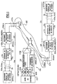
- a two-way telephone link of digital type between two terminal devices of ETTTa and ETTTb data processing includes basically three sections Ua, OP and Ub, like shown in figure 1.
- a first section Ua includes at a customer user the ETTDa terminal equipment and a Ja junction from this terminal equipment to a data circuit termination equipment ETCDa, also called digital line terminal (TNL).
- a second OP segment incomparably more long as the first and third sections is under operator responsibility and has been expanding since data circuit termination equipment ETCDa in front of the junction of first user Ja to other circuit termination equipment ETCDb data, also known as digital terminal line (TNL), constituting the border with the third section Ub.
- the third section is from same type as the first section and is installed at a "second" user.
- the Ub segment includes a Jb junction between the ETCDb termination equipment and terminal data processing equipment ETTDb, with the second user.
- ETTTa and ETTTb terminal equipment transmit data signals SDa and SDb one towards each other and are installations of user telecommunications including example one or more microcomputers, or a server serving a local network, or even a private digital branch exchange.
- the equipment of data circuit termination ETCDa and ETCDb are for example multiplexers.
- the second OP section under the responsibility of the operator consists essentially of a RT telecommunications network for leased lines synchronous or plesiochronous digital data, wired and / or wireless and / or with optical fibers, the two termination devices ETCDa and ETCDb, and two digital user lines LTa and LTb connecting the ETCDa and ETCDb termination equipment line digital terminals respectively TNLa and TNLb constituting network access points RT telecommunications.
- the link between ETTDa and ETTDb terminal equipment is a link synchronized digital leased by the operator OP specially for a user, who can be a service provider, and through which ETTDa and ETTDb terminal equipment communicate in permanence of data signals SDa and SDb.
- the guaranteed speed for this link particularly through the Ja and Jb junctions and telephone lines LTa and LTb is 2048 kbit / s, according to Union recommendation G.703 ITU Telecommunications International, Geneva 1991.
- Data signal transmissions in the junctions Ja and Jb are digital, that is to say for example in high order density bipolar code 3 HDB3.
- the junctions Ja and Jb and the lines LTa and LTb are bidirectional and respectively four wires, or with two optical fibers for example.
- an alarm indication signal SIAa, SIAb, SIAca, SIAcb is emitted by terminal equipment of data processing ETTDa, ETTDb through the Ja, Jb junction and the telecommunications line leased respectively LTa and LTb, or by equipment data circuit termination ETCDa, ETCDb to across the respective leased line LTa, LTb, in PSTN network management when this equipment is failing. All alarm indication signals SIAa, SIAb, SIAca and SIAcb are identical and composed of a sequence of bits "1".
- the CS supervision center includes at least one indication signal detector DI alarm, a GS sequence generator and a UC control unit.
- the DI detector detects a alarm indication signal and GS generator generates test sequences in the link monitored in either direction transmission Ua to Ub, or Ub to Ua, through a CSM separator-mixer circuit at the access point PI intermediary under the control of the unit CPU control.
- each junction of user Ja, Jb includes a device for fault discrimination 1a, 1b according to the invention.
- the devices 1a and 1b being identical, only one of them 1a is described in detail below in reference to figure 2.
- the fault discrimination device 1a includes a transmission circuit 2a for transmitting signals according to the direction of the terminal equipment ETTDa to the ETCDa termination equipment, and a receiving circuit 3a for transmitting signals in the opposite direction of the ETCDa equipment towards ETTDa equipment.
- a time base 4a recovers in input of the receiving circuit 3a the bit clock in an SDb data signal received to provide various clock signals suitable for the units described below, included in circuits 2a and 3a.
- the transmission circuit 2a comprises basically an indication signal detector alarm 20, a lack of signal detector 21, a lack of signal sequence generator 22 controlled by the detector 21, a scrambler 23 controlled by detectors 20 and 21, and a stable three position switch 24 controlled by detectors 20 and 21.
- the inputs of detectors 20 and 21 as well as a first input 241 of switch 24 are connected to the output of the terminal processing equipment corresponding data ETTDa through the junction Ja.
- the first detector 20 detects a signal of alarm indication SIAa emitted by the equipment ETTDa terminal in the Ja junction, when this terminal equipment is faulty.
- the detector 20 commands to through a first entrance to a door OR 25 the reset and activation of the scrambler 23 and the switch from normal state 241 of the switch 24 for the transmission of the data signal SDa, as shown in solid lines in Figure 2, at a state alarm connecting the output of the scrambler 23 to the input of the circuit terminal equipment corresponding data ETCDa through a second input 242 of switch 24.
- detector 20 authorizes opening an ET 26I door to apply the SIAa signal through an OR 26D gate at the entrance of scrambler data 23.
- the scrambler 23 comprises in a known manner a generator generating pseudo-random binary sequences having a length predetermined by example of a few hundred or thousands of bits, in function of a predetermined generator polynomial, so replace the SIAa signal with a sequence SIAEa scrambled alarm indication produced consecutively and repeatedly by the scrambler 23 and cannot be found in any signal digital SDa, SIAa transmitted from the equipment ETTDa terminal.
- the generator pseudo-random is reset to a binary state predetermined before any start of transmission of successive sequences, under the control of the door OR 25. Scrambled signal sequences alarm indication signals are thus transmitted by scrambler 23 through switch 24 to ETCDa termination equipment which retransmits them to the CS supervision center across the line LTa and the TNLa digital line terminal.
- the second detector 21 in the circuit 2a transmit detects a lack of signal in the emission channel of the Ja junction.
- the lack of signal can come from any brief interruption or SDa data signal or SIAa signal input of transmission circuit 2a, such as a stop operation of the ETTDa terminal equipment, by example when the user turns off the equipment terminal after his work day, or a disconnection of terminal equipment and junction Jb, or a cut in the transmission channel of the Ja junction, or even a supply fault ETTDa terminal equipment.
- the detector 21 controls the reset and activation of the scrambler 23 and the changeover from normal state 241 to state alarm 242 of switch 24, through a second entry of OR gate 25, and controls the generation of a sequence of lack of signal MQSa by generator 22.
- the MQSa sequence is by example composed of an alternating sequence of m bits to one first binary state and q bits to a second state binary; for example, when the integers m and q are equal to 1, the sequence MQSa is such that "1010 ... 10".
- the detector 21 commands the opening of a gate AND 26M so that the generator 22 supplies to through the OR gate 26D the MQSa sequence at the scrambler 23 which generates lack sequences scrambled MQSEa signal transmitted across the second input 242 from switch 24 to ETCDa termination equipment.
- MQSEa sequences are different from sequences of the same length contained in a signal SDa, SIAa transmitted by ETTDa terminal equipment.
- a DMD detector After descrambling in the DE descrambler of the supervision center CS, a DMD detector detects the sequence descrambled MQSa to signal to the unit of UC control and therefore the operator that there is a lack of signal at the junction User Ja.
- the respective detector 20 or 21 order through the door OR 25 initialization of the scrambler 23 so that the scrambler always transmits the same start of SIAEa or MQSEa scrambled sequence.
- the scrambler 23, or the generator 22 and the scrambler 23 operate as long as the SIAa signal or lack of signal is present in the Ja junction, the alarm ceasing when the defect which gave rise to it disappears following a maintenance operation on the corresponding defective equipment.
- a delay circuit 27 between the input of the transmission circuit 2a and the first input 241 of the switch 24 delays the SDa data signal applied to switch 24 to compensate for the time in units 20 to 23 during the detection of an SIAa signal or a lack of signal.
- Switch 24 and others in the device la can be relay and two states stable.
- the reception circuit 3a is used to regenerate a SIAb alarm indication signal in the reception of the Ja junction towards ETTDa terminal equipment when the circuit 2b emission in the discrimination device faults 1b at the other end of link a transmitted alarm indication sequences scrambled SIAEb in response to a signal SIAb alarm indication from the other ETTDb terminal equipment, or has transmitted scrambled MQSEb signal loss sequences in response to a lack of signal in the other junction Jb.
- the receiving circuit 3a includes essentially a descrambler 30, a detector 31 detecting an SIAb alarm indication signal, a detector 32 detecting a sequence of lack of signal MQSb, a generator 34 generating a signal alarm indication SIAb, a two-way switch stable positions 35, and a delay circuit 36.
- a first input 351 of switch 35 and a input of the descrambler 30 are connected respectively through delay circuit 36 and directly at the output of the equipment of corresponding data circuit termination ETCDa located on the side of the Ja junction.
- the SDb data signal transmitted by the ETTDb equipment or if necessary a signal of alarm indication SIAcb emitted by the equipment of ETCDb remote termination when it fails, passes through delay circuit 36 and switch 35 to the ETTDa terminal equipment.
- the descrambler 30 When an alarm indication sequence scrambled SIAEb or a lack of signal sequence scrambled MQSEb is received through the equipment of ETCDa termination, the descrambler 30 la descrambles into an SIAb descrambled sequence or MQSb applied to the inputs of detectors 31 and 32.
- detector 31 maintains through a door OR 33 the switch 35 in alarm state by connecting a second input 352 from switch 35 to the output of generator 34 which generates a transmitted SIAb alarm indication signal to the ETTDa equipment.
- the second detector 32 in the receiving circuit 3a command through the OR gate 33 the transmission of the indication signal SIAb alarm from generator 34 to ETTDa terminal equipment through the second input 352 of switch 35, as long as a sequence of lack of scrambled signal MQSEb remains at output ETCDa termination equipment.
- the circuit of delay 36 temporarily compensates for the processing of scrambled sequences and SIA signal generation in units 30 to 34.
- the detector 31 when the detector 31 detects the SIAb descrambled alarm indication signal, it commands the opening of an AND door to apply to through it the detected signal SIAb of the output from descrambler 30 to second input 352 from switch 35.
- the input of the generator 34 is only connected to the output of the detector 32.
- switches 24 and 35 remain at their state before power failure, so that do not disturb the signals that were transmitted in the junction Ja.
- the transmission data signal SDa normal from equipment ETTDa terminal to ETCDa termination equipment through delay circuit 27 and the switch 24, and the normal transmission of the data signal SDb in the opposite direction through the circuit delay 36 and switch 35 are held when a power failure occurs.
- a alarm indication signal SIAa is transmitted by ETTDa terminal equipment, this will still be transmitted through the ETCDa termination equipment, to the CS supervision center, but without discrimination with an alarm indication signal SIAca transmitted by the ETCDa termination equipment, as in the prior art.
- the DI detector still detects an indication signal SIAa or SIAca alarm to signal a fault to the control unit UC.
- the fault discrimination device 1a still includes a sequence detector loopback / loopback 50 and three switches 51, 52 and 53.
- Switches 51 and 52 are respectively placed at the output of the transmission circuit 2a and in input of reception circuit 3a and are controlled simultaneously through an inverter 54 by a control output 50C of detector 30.
- Switch 53 when closed, connects the input of the receiving circuit 3a before switch 52 at the output of the transmission circuit 2a after switch 51.
- Switch 53 and a loopback indicator 55 are controlled by the output of command 50C of the sequence detector 50.
- a location sequence SBDB is transmitted by the sequence generator GS in the supervision center CS through the corresponding equipment of the leased link and the termination equipment ETCDa.
- the control output 50C goes to state "1" which opens the switches 51 and 52 to isolate the terminal equipment ETTDa and the junction Ja of the second section OP, and term the loop switch 53 and turns on the LED 55 in order to loop the output of the termination equipment ETCDa at the input thereof located on the side of the junction Ja.
- test sequence ST is transmitted by the generator GS in the direction of the termination equipment ETCDa, passes through the switch 53 and is returned to the supervision center CS in which a detector DST analyzes the returned sequence ST and the unit control unit measures an error rate to confirm that an alarm previously detected in the form of an SIAca alarm indication signal does correspond to a fault in the link section from the ETCDa termination equipment to the RT network, which is the responsibility of the operator OP.
- the test sequence ST is for example a pseudo-random sequence at 2 15 -1 bits.
- the looping / unwinding sequence SBDB and the ST test sequence are merged into one ST sequence.
- the sequence 50 has a RAM buffer in order to write the ST sequence at the same time as it is detected and read the detected ST sequence there after that the switches 51 and 52 are open and switch 53 is closed to re-inject the ST sequence to the CS supervision center which then measures an error rate.
- Another ST sequence then causes the unwinding in the device 1a.
- the fault discrimination device 1a still includes two controlled switches simultaneously locally 61 and 62 and an indicator 63 to carry out locally controlled loopbacks in located at the user's home.
- Switches 61 and 62 each have three positions P1, P2 and P3 and are respectively located at the input of the transmission circuit 2a or at the output of the reception circuit 3a.
- the device 1a also includes a switch 64 between the output of the sequence generator 34 and the circuit output reception 3a in front of switch 62, and a sequence generator 65 connected to a third input 243 of switch 24.
- switches 61 and 62 connect the output and input of ETTDa terminal equipment at the circuit entrance 2a and at the output of the receiving circuit 3a to allow normal signals to pass SDa and SDb data.
- the indicator 63 remains off.
- the switches 61 and 62 connect the circuit output 3a after switch 35 at the entrance to the transmission circuit 2a before the inputs of the detectors 20 and 21 and the delay circuit 27.
- the end of the LTa telecommunication line in device 1a is thus closed, which is signaled by a continuous lighting of the indicator 63.
- a sequence of identical or different test of SBDB and ST sequences is then transmitted by the GS generator.
- an indication signal SIAb alarm is transmitted from generator 34 to the ETTDa terminal equipment, through the switch 64 commanded to close locally in correspondence with position P2 of switches 61 and 62, to indicate to the ETTDa equipment that the link is no longer available.
- the switches 61 and 62 connect the end of the track from the Ja junction located on the side of the input of the transmission circuit 2a at the end of the reception path of the junction Ja located on the side of the output of the reception circuit 3a. Entrance and ETTDa equipment outputs are thus looped through across the Ja junction in front of the device the which is indicated by a flashing of the indicator 63. This loop in the user stretch Ua can be then tested from the ETTDa terminal equipment.
- the sequence generator 65 emits a SBDB loop sequence, or alternatively a ST test sequence, so that detector 50 in the device 1b loops the LTb line by closing the switch 53 in the device 1b, indicating thus to the remote device ETTDb the unavailability of the link and to the CS supervision center the state of maintenance.
- the fault discriminator la been illustrated according to a preferred embodiment of the invention.
- Other achievements may be envisaged from this illustrated embodiment.
- the lack of signal detector 21 can be supplemented by a detector of other anomalies in the emission path of the Ja junction which are not not likely to be detected by the equipment of ETCDa termination and which generate the emission of a particular sequence generated by another generator that generator 22 and scrambled by the scrambler 23; in this realization, a detector other than detector 32 is provided in parallel with detectors 31 and 32 to detect the particular sequence descrambled by the descrambler 30.
- the switches 51, 52 and 53 which are of the relay type or with low consumption transistors current, like switches 61 and 62, are located at other locations in the device la, by example respectively located on the side of the junction Ja and on the side of line LTa, or all on the same side.
Landscapes
- Engineering & Computer Science (AREA)
- Computer Networks & Wireless Communication (AREA)
- Signal Processing (AREA)
- Environmental & Geological Engineering (AREA)
- Maintenance And Management Of Digital Transmission (AREA)
Abstract
Description
- la figure 1 est un bloc-diagramme schématique d'une liaison de télécommunication à travers un réseau de liaisons louées numériques et entre deux équipements terminaux reliés à des dispositifs de discrimination de défauts selon l'invention; et
- la figure 2 est un bloc-diagramme détaillé d'un dispositif de discrimination de défauts selon l'invention, des commutateurs dans ce dispositif étant illustrés en état normal de transmission/réception de signaux de données.
- un défaut provenant du deuxième tronçon OP de la liaison louée, c'est-à-dire un signal d'alarme non embrouillé SIAca émis par l'équipement de terminaison de circuit de données ETCDa lorsque celui-ci est défaillant, ou le cas échéant émis par un équipement, tel que le terminal TNLa, précédant le point d'accès intermédiaire PI, et
- un défaut provenant du premier tronçon Ua indiqué par un signal d'indication d'alarme SIAa émis par l'équipement terminal ETTDa et remplacé par la séquence d'indication d'alarme embrouillée SIAEa dans le dispositif de discrimination de défauts la, lorsque l'équipement terminal ETTDa est défaillant.
Claims (18)
- Dispositif pour discriminer des défauts de fonctionnement qui sont signalés respectivement par des signaux d'indication d'alarme identiques (SIAa, SIAca) transmis dans une ligne de télécommunication (LTa) depuis un premier équipement (ETTDa) à travers un deuxième équipement (ETCDa) et depuis le deuxième équipement (ETCDa) connecté à la ligne de télécommunication, caractérisé en ce que le dispositif (1a) est interconnecté entre le premier équipement (ETTDa) et le deuxième équipement (ETCDa) et comprend un moyen (20, 23, 24) pour remplacer le signal d'indication d'alarme (SIAa) transmis depuis le premier équipement (ETTDa) par un signal d'alarme (SIAEa) qui ne se retrouve pas dans un signal (SDa, SIAa) transmis par le premier équipement (ETTDa) et qui est transmis dans la ligne de télécommunication (LTa) à travers le deuxième équipement (ETCDa).
- Dispositif conforme à la revendication 1, dans lequel le moyen pour remplacer comprend un détecteur (20) pour détecter le signal d'indication d'alarme (SIAa) transmis depuis le premier équipement (ETTDa), un embrouilleur (23) pour embrouiller le signal d'indication d'alarme détecté en des séquences d'indication d'alarme embrouillées (SIAEa) constituant le signal d'alarme, et un moyen de commutation (24) commandé par le détecteur (20) ayant un premier état (241) à travers lequel un signal de données (SDa) est transmis par le premier équipement (ETTDa) vers le deuxième équipement (ETCDa) et un deuxième état (242) à travers lequel les séquences d'indication d'alarme embrouillées (SIAEa) sont transmises par l'embrouilleur (23) vers le deuxième équipement (ETCDa) tant que le signal d'indication d'alarme (SIAa) est détecté.
- Dispositif conforme à la revendication 1 ou 2, comprenant un moyen (21, 22, 23, 24) pour transmettre vers la ligne de télécommunication (LTa) à travers le deuxième équipement (ETCDa) un signal de manque de signal (MQSEa) qui ne se retrouve pas dans le signal (SDa, SIAa), tant qu'il y a un manque de signal en sortie (Ja) du premier équipement (ETTDa).
- Dispositif conforme à la revendication 3 lorsqu'elle dépend de la revendication 2, dans lequel le moyen pour transmettre comprend un deuxième détecteur (21) pour détecter un manque de signal en sortie (Ja) du premier équipement (ETTDa), et un générateur (22) pour générer des séquences de manque de signal (MQSa) qui sont embrouillées par l'embrouilleur (23) en des séquences de manque de signal embrouillées (MQSEa) transmises vers le deuxième équipement (ETCDa) à travers le moyen de commutation (24) audit deuxième état (242) tant que le manque de signal est détecté.
- Dispositif conforme à l'une quelconque des revendications 1 à 4, comprenant un deuxième moyen (30, 31, 34, 35) pour remplacer un deuxième signal d'alarme (SIAEb) reçu au moins à travers la ligne de télécommunication (LTa) et le deuxième équipement (ETCDa) par un deuxième signal d'indication d'alarme (SIAb) transmis au premier équipement (ETTDa).
- Dispositif conforme à la revendication 5, dans lequel le deuxième moyen pour remplacer comprend un désembrouilleur (30) pour désembrouiller des deuxièmes séquences d'indication d'alarme embrouillées (SIAEb) constituant le deuxième signal d'alarme en un deuxième signal d'indication d'alarme (SIAb), un troisième détecteur (31) pour détecter le deuxième signal d'indication d'alarme, et un deuxième moyen de commutation (35) commandé par le troisième détecteur (31) ayant un premier état (351) à travers lequel un signal de données (SDb) reçu au moins à travers la ligne de télécommunication (LTa) et le deuxième équipement (ETCDa) est transmis vers le premier équipement (ETTDa) et un deuxième état (352) à travers lequel le deuxième signal d'indication d'alarme détecté (SIAb) est transmis vers le premier équipement (ETTDa), ou à travers lequel le deuxième signal d'indication (SIAb) reproduit dans un générateur de signal d'indication d'alarme (34) est transmis vers le premier équipement, tant que le deuxième signal d'indication d'alarme est détecté.
- Dispositif conforme à l'une quelconque des revendications 1 à 6, comprenant un troisième moyen (30, 32, 34, 35) pour remplacer un deuxième signal de manque de signal (MQSEb) reçu au moins à travers depuis la ligne de télécommunication (LTa) et le deuxième équipement (ETCDa) par un deuxième signal d'indication d'alarme (SIAb) transmis au premier équipement (ETTDa).
- Dispositif conforme à la revendication 7 lorsqu'elle dépend de la revendication 6, dans lequel le troisième moyen pour remplacer comprend un quatrième détecteur (32) pour détecter des deuxièmes séquences de manque de signal (MQSb) produites par le désembrouilleur (30) en réponse à des deuxièmes séquences de manque de signal embrouillées (MQSEb) constituant le deuxième signal de manque de signal, et un générateur (34) pour générer le deuxième signal d'indication d'alarme (SIAb) transmis vers le premier équipement (ETTDa) à travers le deuxième moyen de commutation (35) audit deuxième état tant que des deuxièmes séquences de manque de signal (MQSb) sont détectées.
- Dispositif conforme à la revendication 4, ou à la revendication 2, dans lequel chaque séquence de manque de signal (MQSa ; MQSb) comprend une suite alternée de bits à un premier état en nombre prédéterminé et de bits à un deuxième état en nombre prédéterminé.
- Dispositif conforme à l'une quelconque des revendications 1 à 9, pour lequel le premier équipement est un équipement terminal de traitement de données (ETTDa), le deuxième équipement est un équipement de terminaison de circuit de données (ETCDa), et la ligne de télécommunication est une ligne de transmission numérique (LTa).
- Dispositif conforme à l'une quelconque des revendications 1 à 10, comprenant un moyen (50) pour détecter une séquence prédéterminée (SBDB, ST) reçue depuis la sortie du deuxième équipement (ETCDa), et un moyen (51, 52, 53) pour boucler la sortie et l'entrée du deuxième équipement (ETCDa) en réponse à la séquence prédéterminée détectée.
- Dispositif conforme à l'une quelconque des revendications 1 à 11, comprenant un moyen de bouclage (61, 62) pour boucler soit la sortie et l'entrée du deuxième équipement (ETCDa), soit la sortie et l'entrée du premier équipement (ETTDa).
- Dispositif conforme à la revendication 12, comprenant un moyen (34, 64) pour générer un deuxième signal d'indication d'alarme (SIAb) transmis vers le premier équipement (ETTDa) lorsque le moyen de bouclage (61, 62) boucle la sortie et l'entrée du deuxième équipement (ETCDa).
- Dispositif conforme à la revendication 12 ou 13, comprenant un moyen (65, 243) pour générer une séquence prédéterminée (ST, SBDB) dans la ligne de télécommunication (LTa) à travers le deuxième équipement (ETCDa) lorsque le moyen de bouclage (61, 62) boucle la sortie et l'entrée du premier équipement (ETTDa).
- Centre de supervision (CS) pour superviser une ligne de télécommunication (LTa) équipée d'un dispositif (1a) interconnecté entre un premier équipement (ETTDa) et un deuxième équipement (ETCDa) connecté à la ligne de télécommunication pour discriminer des défauts de fonctionnement conforme à l'une quelconque des revendications 1 à 14, caractérisé en ce qu'il comprend un premier moyen (DI) pour détecter un signal d'indication d'alarme (SIAca) susceptible d'être transmis depuis le deuxième équipement (ETCDa), et un deuxième moyen (DE, DID) pour détecter un signal d'alarme (SIAEa) différent du signal d'indication d'alarme et transmis par ledit dispositif (1a) en remplacement d'un signal d'indication d'alarme (SIAa) transmis depuis le premier équipement (ETTDa).
- Centre de supervision conforme à la revendication 15, dans lequel le deuxième moyen pour détecter comprend un désembrouilleur (DE) pour désembrouiller tout signal reçu de la ligne de télécommunication (LTa) en un signal désembrouillé, et un détecteur (DID) pour détecter un signal d'indication d'alarme (SIAa) dans le signal désembrouillé.
- Centre de supervision conforme à la revendication 15 ou 16, comprenant un moyen (DE, DMD) pour détecter un signal de manque de signal (MQSEa) transmis par ledit dispositif (1a) tant qu'il y a un manque de signal en sortie (Ja) du premier équipement (ETTDa).
- Centre de supervision conforme à la revendication 16, comprenant un deuxième détecteur (DMD) pour détecter dans le signal désembrouillé des séquences de manque de signal (MQSa) générées et embrouillées dans ledit dispositif (1a) tant qu'il y a un manque de signal en sortie (Ja) du premier équipement (ETTDa).
Applications Claiming Priority (2)
| Application Number | Priority Date | Filing Date | Title |
|---|---|---|---|
| FR9900259 | 1999-01-11 | ||
| FR9900259A FR2788396B1 (fr) | 1999-01-11 | 1999-01-11 | Dispositif de discrimination de defauts dans une liaison louee numerique |
Publications (2)
| Publication Number | Publication Date |
|---|---|
| EP1021016A1 true EP1021016A1 (fr) | 2000-07-19 |
| EP1021016B1 EP1021016B1 (fr) | 2005-10-19 |
Family
ID=9540804
Family Applications (1)
| Application Number | Title | Priority Date | Filing Date |
|---|---|---|---|
| EP00400024A Expired - Lifetime EP1021016B1 (fr) | 1999-01-11 | 2000-01-05 | Dispositif de discrimination de défauts dans une liaison louée numérique |
Country Status (4)
| Country | Link |
|---|---|
| EP (1) | EP1021016B1 (fr) |
| DE (1) | DE60023199T2 (fr) |
| ES (1) | ES2246815T3 (fr) |
| FR (1) | FR2788396B1 (fr) |
Citations (3)
| Publication number | Priority date | Publication date | Assignee | Title |
|---|---|---|---|---|
| JPH0423537A (ja) * | 1990-05-17 | 1992-01-27 | Fujitsu Ltd | 状態監視方法 |
| US5461628A (en) * | 1993-06-18 | 1995-10-24 | Nec Corporation | Network system capable of network elements with decreasing load of a monitoring device |
| US5768501A (en) * | 1996-05-28 | 1998-06-16 | Cabletron Systems | Method and apparatus for inter-domain alarm correlation |
-
1999
- 1999-01-11 FR FR9900259A patent/FR2788396B1/fr not_active Expired - Lifetime
-
2000
- 2000-01-05 ES ES00400024T patent/ES2246815T3/es not_active Expired - Lifetime
- 2000-01-05 EP EP00400024A patent/EP1021016B1/fr not_active Expired - Lifetime
- 2000-01-05 DE DE60023199T patent/DE60023199T2/de not_active Expired - Lifetime
Patent Citations (3)
| Publication number | Priority date | Publication date | Assignee | Title |
|---|---|---|---|---|
| JPH0423537A (ja) * | 1990-05-17 | 1992-01-27 | Fujitsu Ltd | 状態監視方法 |
| US5461628A (en) * | 1993-06-18 | 1995-10-24 | Nec Corporation | Network system capable of network elements with decreasing load of a monitoring device |
| US5768501A (en) * | 1996-05-28 | 1998-06-16 | Cabletron Systems | Method and apparatus for inter-domain alarm correlation |
Also Published As
| Publication number | Publication date |
|---|---|
| FR2788396A1 (fr) | 2000-07-13 |
| EP1021016B1 (fr) | 2005-10-19 |
| ES2246815T3 (es) | 2006-03-01 |
| FR2788396B1 (fr) | 2001-02-09 |
| DE60023199T2 (de) | 2006-06-22 |
| DE60023199D1 (de) | 2006-03-02 |
Similar Documents
| Publication | Publication Date | Title |
|---|---|---|
| US5343461A (en) | Full duplex digital transmission facility loop-back test, diagnostics and maintenance system | |
| US7471637B2 (en) | Method and system for monitoring idle network circuits | |
| EP0032327A2 (fr) | Procédé et installation de sécurisation d'une artère de transmission numérique | |
| EP0200842A1 (fr) | Modem de contrôle d'un réseau de modems | |
| CA2040941C (fr) | Procede et dispositif de retour a une liaison normale apres utilisation d'une liaison de secours dans un systeme de transmission de donnees | |
| US6392992B1 (en) | Signal degrade oscillation control mechanism | |
| EP0369276B1 (fr) | Système d'échange de messages en temps réel entre stations reliées par une liaison en boucle, notamment entre stations d'un central de télécommunications | |
| US8248954B2 (en) | System and method for enhancement of Ethernet link loss forwarding | |
| AU2004317680A1 (en) | Fault management in a ethernet based communication system | |
| EP1021016B1 (fr) | Dispositif de discrimination de défauts dans une liaison louée numérique | |
| EP0199294B1 (fr) | Procédé et dispositif de télésignalisation pour une liaison de transmission numérique bidirectionnnelle | |
| EP0774879B1 (fr) | Système de surveillance et de gestion d'un réseau d'accès point-multipoint | |
| FR2466143A1 (fr) | Procede et dispositif de test automatique d'un systeme de transmission de donnees numeriques | |
| US7389044B2 (en) | Method and system for providing a signature signal in an optical network in the event of loss of a client | |
| FR2845772A1 (fr) | Procede de detection de defaut de blindage d'un cable multifilaire | |
| AU695267B2 (en) | In-service monitoring in communications networks | |
| FR2691029A1 (fr) | Procédé d'analyse à distance de données d'un protocole, terminal d'abonné spécialisé et dispositif d'analyse distant correspondant. | |
| EP0381104B1 (fr) | Dispositif de raccordement d'une chaîne centrale de connexion à des unités de raccordement | |
| FR2668003A1 (fr) | Equipement de test a distance du protocole sur l'interface s et t d'un equipement terminal rnis. | |
| EP0395483B1 (fr) | Système de télécommunication en double boucle fermée | |
| FR2641430A1 (fr) | Reseau en anneau comportant une boucle de secours | |
| JPS6033764A (ja) | 中継器監視方式 | |
| JP2956391B2 (ja) | 光加入者伝送装置の加入者線インタフェース部 | |
| EP0629070B1 (fr) | Transcodage/codage des fanions d'origine sur une liaison numérique HDLC | |
| JPH05133839A (ja) | レピータ用光ケーブル不具合検出装置 |
Legal Events
| Date | Code | Title | Description |
|---|---|---|---|
| PUAI | Public reference made under article 153(3) epc to a published international application that has entered the european phase |
Free format text: ORIGINAL CODE: 0009012 |
|
| AK | Designated contracting states |
Kind code of ref document: A1 Designated state(s): DE ES GB IT |
|
| AX | Request for extension of the european patent |
Free format text: AL;LT;LV;MK;RO;SI |
|
| 17P | Request for examination filed |
Effective date: 20000726 |
|
| RIN1 | Information on inventor provided before grant (corrected) |
Inventor name: JOURNEL, JACQUES |
|
| AKX | Designation fees paid |
Free format text: DE ES GB IT |
|
| GRAP | Despatch of communication of intention to grant a patent |
Free format text: ORIGINAL CODE: EPIDOSNIGR1 |
|
| RIN1 | Information on inventor provided before grant (corrected) |
Inventor name: JOURNEL, JACQUES |
|
| GRAS | Grant fee paid |
Free format text: ORIGINAL CODE: EPIDOSNIGR3 |
|
| GRAA | (expected) grant |
Free format text: ORIGINAL CODE: 0009210 |
|
| AK | Designated contracting states |
Kind code of ref document: B1 Designated state(s): DE ES GB IT |
|
| REG | Reference to a national code |
Ref country code: GB Ref legal event code: FG4D Free format text: NOT ENGLISH |
|
| GBT | Gb: translation of ep patent filed (gb section 77(6)(a)/1977) |
Effective date: 20060116 |
|
| REG | Reference to a national code |
Ref country code: ES Ref legal event code: FG2A Ref document number: 2246815 Country of ref document: ES Kind code of ref document: T3 |
|
| REF | Corresponds to: |
Ref document number: 60023199 Country of ref document: DE Date of ref document: 20060302 Kind code of ref document: P |
|
| REG | Reference to a national code |
Ref country code: GB Ref legal event code: 732E |
|
| PLBE | No opposition filed within time limit |
Free format text: ORIGINAL CODE: 0009261 |
|
| STAA | Information on the status of an ep patent application or granted ep patent |
Free format text: STATUS: NO OPPOSITION FILED WITHIN TIME LIMIT |
|
| 26N | No opposition filed |
Effective date: 20060720 |
|
| REG | Reference to a national code |
Ref country code: ES Ref legal event code: PC2A |
|
| REG | Reference to a national code |
Ref country code: GB Ref legal event code: 732E Free format text: REGISTERED BETWEEN 20090326 AND 20090401 |
|
| REG | Reference to a national code |
Ref country code: DE Ref legal event code: R082 Ref document number: 60023199 Country of ref document: DE Representative=s name: JOCHEN MUELLER, DE |
|
| REG | Reference to a national code |
Ref country code: DE Ref legal event code: R082 Ref document number: 60023199 Country of ref document: DE Representative=s name: JOCHEN MUELLER, DE |
|
| REG | Reference to a national code |
Ref country code: DE Ref legal event code: R082 Ref document number: 60023199 Country of ref document: DE Representative=s name: MAIWALD GMBH PATENTANWAELTE, DE Effective date: 20120131 Ref country code: DE Ref legal event code: R082 Ref document number: 60023199 Country of ref document: DE Representative=s name: MAIWALD GMBH PATENTANWAELTE, DE Effective date: 20120507 Ref country code: DE Ref legal event code: R081 Ref document number: 60023199 Country of ref document: DE Owner name: SAGEMCOM ENERGY & TELECOM SAS, FR Free format text: FORMER OWNER: SAGEM COMMUNICATION, PARIS, FR Effective date: 20120507 Ref country code: DE Ref legal event code: R082 Ref document number: 60023199 Country of ref document: DE Representative=s name: MAIWALD PATENTANWALTS- UND RECHTSANWALTSGESELL, DE Effective date: 20120131 Ref country code: DE Ref legal event code: R082 Ref document number: 60023199 Country of ref document: DE Representative=s name: MAIWALD PATENTANWALTS- UND RECHTSANWALTSGESELL, DE Effective date: 20120507 |
|
| REG | Reference to a national code |
Ref country code: GB Ref legal event code: 732E Free format text: REGISTERED BETWEEN 20130509 AND 20130515 |
|
| REG | Reference to a national code |
Ref country code: DE Ref legal event code: R082 Ref document number: 60023199 Country of ref document: DE Representative=s name: MAIWALD GMBH PATENTANWAELTE, DE Effective date: 20130613 Ref country code: DE Ref legal event code: R081 Ref document number: 60023199 Country of ref document: DE Owner name: SAGEMCOM ENERGY & TELECOM SAS, FR Free format text: FORMER OWNER: SAGEM TELECOMMUNICATIONS S. A., PARIS, FR Effective date: 20130613 Ref country code: DE Ref legal event code: R082 Ref document number: 60023199 Country of ref document: DE Representative=s name: MAIWALD PATENTANWALTS- UND RECHTSANWALTSGESELL, DE Effective date: 20130613 |
|
| REG | Reference to a national code |
Ref country code: ES Ref legal event code: PC2A Owner name: SAGEMCOM ENERGY & TELECOM SAS Effective date: 20131009 |
|
| REG | Reference to a national code |
Ref country code: DE Ref legal event code: R082 Ref document number: 60023199 Country of ref document: DE Representative=s name: MAIWALD PATENTANWALTS- UND RECHTSANWALTSGESELL, DE |
|
| PGFP | Annual fee paid to national office [announced via postgrant information from national office to epo] |
Ref country code: GB Payment date: 20181219 Year of fee payment: 20 |
|
| PGFP | Annual fee paid to national office [announced via postgrant information from national office to epo] |
Ref country code: IT Payment date: 20190102 Year of fee payment: 20 Ref country code: ES Payment date: 20190201 Year of fee payment: 20 Ref country code: DE Payment date: 20181218 Year of fee payment: 20 |
|
| REG | Reference to a national code |
Ref country code: DE Ref legal event code: R071 Ref document number: 60023199 Country of ref document: DE |
|
| REG | Reference to a national code |
Ref country code: GB Ref legal event code: PE20 Expiry date: 20200104 |
|
| PG25 | Lapsed in a contracting state [announced via postgrant information from national office to epo] |
Ref country code: GB Free format text: LAPSE BECAUSE OF EXPIRATION OF PROTECTION Effective date: 20200104 |
|
| REG | Reference to a national code |
Ref country code: ES Ref legal event code: FD2A Effective date: 20200804 |
|
| PG25 | Lapsed in a contracting state [announced via postgrant information from national office to epo] |
Ref country code: ES Free format text: LAPSE BECAUSE OF EXPIRATION OF PROTECTION Effective date: 20200106 |