EP1020967B1 - A device for and a method of pulsing and amplifying singlemode laser light - Google Patents
A device for and a method of pulsing and amplifying singlemode laser light Download PDFInfo
- Publication number
- EP1020967B1 EP1020967B1 EP00300202A EP00300202A EP1020967B1 EP 1020967 B1 EP1020967 B1 EP 1020967B1 EP 00300202 A EP00300202 A EP 00300202A EP 00300202 A EP00300202 A EP 00300202A EP 1020967 B1 EP1020967 B1 EP 1020967B1
- Authority
- EP
- European Patent Office
- Prior art keywords
- light
- resonator
- laser
- singlemode
- optical
- Prior art date
- Legal status (The legal status is an assumption and is not a legal conclusion. Google has not performed a legal analysis and makes no representation as to the accuracy of the status listed.)
- Expired - Lifetime
Links
Images


Classifications
-
- G—PHYSICS
- G02—OPTICS
- G02F—OPTICAL DEVICES OR ARRANGEMENTS FOR THE CONTROL OF LIGHT BY MODIFICATION OF THE OPTICAL PROPERTIES OF THE MEDIA OF THE ELEMENTS INVOLVED THEREIN; NON-LINEAR OPTICS; FREQUENCY-CHANGING OF LIGHT; OPTICAL LOGIC ELEMENTS; OPTICAL ANALOGUE/DIGITAL CONVERTERS
- G02F1/00—Devices or arrangements for the control of the intensity, colour, phase, polarisation or direction of light arriving from an independent light source, e.g. switching, gating or modulating; Non-linear optics
- G02F1/35—Non-linear optics
- G02F1/37—Non-linear optics for second-harmonic generation
-
- H—ELECTRICITY
- H01—ELECTRIC ELEMENTS
- H01S—DEVICES USING THE PROCESS OF LIGHT AMPLIFICATION BY STIMULATED EMISSION OF RADIATION [LASER] TO AMPLIFY OR GENERATE LIGHT; DEVICES USING STIMULATED EMISSION OF ELECTROMAGNETIC RADIATION IN WAVE RANGES OTHER THAN OPTICAL
- H01S3/00—Lasers, i.e. devices using stimulated emission of electromagnetic radiation in the infrared, visible or ultraviolet wave range
- H01S3/005—Optical devices external to the laser cavity, specially adapted for lasers, e.g. for homogenisation of the beam or for manipulating laser pulses, e.g. pulse shaping
- H01S3/0057—Temporal shaping, e.g. pulse compression, frequency chirping
-
- G—PHYSICS
- G02—OPTICS
- G02F—OPTICAL DEVICES OR ARRANGEMENTS FOR THE CONTROL OF LIGHT BY MODIFICATION OF THE OPTICAL PROPERTIES OF THE MEDIA OF THE ELEMENTS INVOLVED THEREIN; NON-LINEAR OPTICS; FREQUENCY-CHANGING OF LIGHT; OPTICAL LOGIC ELEMENTS; OPTICAL ANALOGUE/DIGITAL CONVERTERS
- G02F1/00—Devices or arrangements for the control of the intensity, colour, phase, polarisation or direction of light arriving from an independent light source, e.g. switching, gating or modulating; Non-linear optics
- G02F1/35—Non-linear optics
- G02F1/353—Frequency conversion, i.e. wherein a light beam is generated with frequency components different from those of the incident light beams
- G02F1/3542—Multipass arrangements, i.e. arrangements to make light pass multiple times through the same element, e.g. using an enhancement cavity
Landscapes
- Physics & Mathematics (AREA)
- Nonlinear Science (AREA)
- Electromagnetism (AREA)
- Optics & Photonics (AREA)
- Engineering & Computer Science (AREA)
- Plasma & Fusion (AREA)
- General Physics & Mathematics (AREA)
- Lasers (AREA)
Description
- The present invention relates to a device for and a method of pulsing and amplifying a singlemode laser light.
- Recently, pulse oscillation lasers have been developed to a remarkable extent, such that now pulse lasers of various ultra short time oscillations have been proposed. In such a pulse laser, owing to the indeterminacy principle between energy and time, the line width of the laser light broadens as the oscillations become ultra short time, thus reducing the monochromaticity of the emitted light. However, if the laser light from a single frequency laser with an excellent monochromaticity of the continuous oscillation is pulsed, though there is a certain limit to shortening the oscillation time, pulsing (the optical output pulse is outputted for a short time), while maintaining accurate monochromaticity, becomes possible.
- Previously-proposed ways in which laser light of the continuous oscillation is pulsed are: (1) a method of using a mechanical chopper, in which light is intercepted by rotating a disk with a hole so as to intercept light, except when the light is passed through the hole, and (2) a method of using an optical chopper, in which the polarizing direction of light is changed with an electro-optic (Electro Optic : EO) element and an acousto-optic (Acousto Optical: AO) element, and the phenomenon that the light does not pass a polarizer set up after these elements.
- However, the power of the thus obtained laser pulse light (power output) becomes lower, since the amplitude of light (strength of light) does not change before and after the pulsing when the continuous oscillation laser light is pulsed by using the above described mechanical chopper and optical chopper, and the amplification operation of the amplitude of light (strength of light) cannot be achieved.
- Accordingly, it is desirable to eliminate the above described disadvantages of the conventional device for and method of obtaining a high power laser pulse light.
- It is also desirable to provide a device for and a method of obtaining a high power ― laser pulse light with good monochromaticity from the singlemode laser light.
- According to a first aspect of the present invention, there is provided a device for pulsing and amplifying a singlemode laser light comprising: a singlemode laser for generating laser light of the singlemode; an optical resonator into which the laser light outputted from the singlemode laser is introduced; and a controller for controlling the length (L) of the resonator by changing the length (L) of the optical resonator based on a control waveform signal, the device being characterised by: a signal generator which generates an asymmetrical triangular repeated waveform signal for use as the control waveform signal to change the length (L) of the resonator, thereby to output laser pulse light of the singlemode with amplified optical strength from the optical resonator.
- In such an embodiment, the resonator length of the optical resonator, into which the laser light emanated from the singlemode laser is introduced, changes based on the controlling waveform signal according to the resonator length controller. The amplification of the optical power causes when the resonator length becomes a multiple of the half-wave length of the incident laser light during the change in the resonator length of the optical resonator, and the optical power (strength) becomes 0 at the rest. Therefore, the laser pulse light of the singlemode with high power can be obtained as a power output of the optical resonator.
- Preferably, the device further comprises an optical path interception means to intercept the optical path between the singlemode laser and the optical resonator; and a driving means for operating the optical path interception means from the leading time of the laser pulse light output from the optical resonator during the fixed time after a lapse of the given delay time; so that by intercepting the optical path between the singlemode laser and the optical resonator, laser pulse light of the singlemode with amplified optical strength having a shorter trailing time is output from the optical resonator.
- In such an embodiment, the resonator length of the light resonator into which the laser light emanated from the singlemode laser is introduced, changes based on the controlling waveform signal according to the resonator length controller. Since the amplification of the optical strength causes when the resonator length becomes a multiple of the half-wave length of the incident laser light during the change in the resonator length of the optical resonator, and the optical strength becomes 0 at the rest, the laser pulse light is output from the optical resonator. And, since the driving means operates with a certain time the optical path interception means by which the optical path between the singlemode laser and the optical resonator is intercepted from the leading time of the laser pulse light after a lapse of the given delay time.
The laser pulse light of the singlemode having high power as a power output of the optical resonator and the shortened trailing time, can be obtained. - It is also preferable that a double wave generating element is provided in the optical resonator, and the laser pulse light outputted from the optical resonator is made double wave.
- In such an embodiment, since the double wave generating element is installed in the optical resonator, the laser pulse light output from the optical resonator can be made twice wave by the double wave generating element.
- According to a second aspect of the present invention, there is provided a method of pulsing and amplifying a singlemode laser light, which method comprises the steps of: introducing laser light emanated from a singlemode laser (1) into an optical resonator; and changing the resonator length (L) of the optical resonator based on a controlling waveform signal; the method being characterised by the steps of: using an asymmetrical triangular repeated waveform signal as the controlling waveform signal; and outputting singlemode laser pulse light of amplified optical strength from the optical resonator.
- In such a method, the resonator length of the optical resonator into which the laser light emanated from the singlemode laser is introduced, changes based on the controlling waveform signal, the amplification of the optical strength causes when the resonator length becomes a multiple of the half-wave length of the incident laser light during the change in the resonator length of the optical resonator, and the optical strength becomes 0 at the rest, therefore, the laser pulse light of the singlemode can be obtained with high power, as an output of the light resonator.
- Preferably, the method further comprises the steps of intercepting the optical path between the singlemode laser and light resonator after a lapse of given delay time from the leading time of laser pulse light output from the optical resonator for a certain time so as to output from the light resonator singlemode laser pulse light of amplified optical strength having shorter trailing time.
- In such a method, the resonator length of the optical resonator into which the laser light emanated from the singlemode laser is introduced, changes based on the controlling waveform signal, the amplification of the optical strength causes when the resonator length becomes a multiple of the half-wave length of the incident laser light during the change in the resonator length of the optical resonator, since the optical strength becomes 0 at the rest, the laser pulse light is output from the optical resonator. Also, the optical path between the singlemode laser and the optical resonator is certain time intercepted from the leading time of the laser pulse light after a lapse of the given delay time, so that the laser pulse light of the singlemode having high power as a power output of the optical resonator and the shortened trailing time, can be obtained.
- In a preferable embodiment of the method of pulsing and amplifying a singlemode laser light according to the present invention, a double wave generating element is provided with the light resonator, thereby making the laser pulse light outputted from the light resonator wave-doubling.
- In such a method, since the double wave generating element is installed in the optical resonator, the laser pulse light output from the optical resonator can be made twice wave by the double wave generating element.
- Reference will now be made, by way of example, to the accompanying drawings, in which:
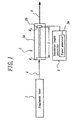
- Fig. 1 shows an explanatory side view of a first device for pulsing and amplifying singlemode laser light embodying the present invention;
- Fig. 2 (a) is an explanatory view showing a resonator length control performed by a resonator length controller in the first embodiment and the controlling waveform signal to be used for it;
- Fig. 2 (b) is an explanatory view showing a waveform of a laser pulse light outputted by the optical resonator in the first embodiment;
- Fig. 3 is an explanatory view showing a shape of waves of the laser pulse light outputted from the optical resonator in the first embodiment;
- Figs. 4 (a) - (d) are explanatory views for explaining operations of the device for pulsing and amplifying singlemode laser light of the first embodiment compared to a previously-proposed device;
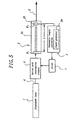
- Fig. 5 shows an explanatory side view of a second device for pulsing and amplifying singlemode laser light embodying the present invention.
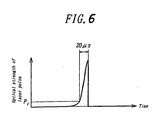
- Fig. 6 is an explanatory view showing a shape of waves of the laser pulse light outputted from the optical resonator in the second embodiment; and
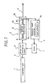
- Fig. 7 shows an explanatory side view of a third device for pulsing and amplifying singlemode laser light embodying the present invention.
-
- Now to the drawings, there are shown various embodiments of the present invention. Like parts are shown by corresponding reference characters throughout several views of the drawings.
- Hereafter, embodiments of the present invention are explained in detail based on the drawings. Fig. 1 is a block diagram showing a constitution of a device for pulsing and amplifying a singlemode laser light according to a first embodiment of the present invention. The device for pulsing and amplifying a singlemode laser light comprises a singlemode laser 1, an
optical resonator 2, and aresonator length controller 3. - The single frequency laser of the continuous oscillation having excellent monochromaticity is used as the above singlemode laser 1; although a titanium sapphire laser having laser power = 1-1000 mW and laser wavelength λ = 400-2000 nm is assumed to be used in this embodiment, a semiconductor laser, a dye laser, a solid state laser, and a gas laser, or the like may be used instead.
- The above
optical resonator 2 comprises ahousing 2a, a couple of mirrors M1 and M2 arranged in opposition to thehousing 2a, and amoving mechanism 2b, by which the mirror M2 is relatively moved by a given slight distance to the mirror M1, themoving mechanism 2b using, for example a piezo element. Length L of the resonator of this optical resonator 2 (a distance between the mirror M1 and the mirror M2 shown in Fig. 1) changes continuously from minimum value Lmin to maximum value Lmax as shown in Fig. 2(a). The shape of optical resonator changes continuously along with it, too. - The
signal generator 3a which generates a controlling waveform signal, is built into the aboveresonator length controller 3. Resonator length L is changed continuously (periodically) by driving themoving mechanism 2b of theoptical resonator 2 based on the controlling waveform signal. In this embodiment, a function generator is used as theabove signal generator 3a, and a signal having an asymmetrical triangular repeated waveform is used as the controlling waveform signal, as shown in Fig. 2(a). In this asymmetrical triangular repeated waveform signal, the leading edge portion of the asymmetrical triangle is set for the speed by which the length L of the resonator is changed to quicken more than the trailing edge portion thereof. - Next, the operation of this embodiment is explained. A laser light 4 (continuous oscillation light) emanated from a singlemode laser 1 is introduced into a
light resonator 2, and a resonator length L thereof is continuously changed by aresonator length controller 3. Concretely, an asymmetrical triangular repeated waveform signal as illustrated in Fig. 2(a) is generated by asignal generator 3a. Length L of the resonator is periodically changed from a minimum value Lmin to a maximum value Lmax by using this signal. In this case, only when the resonator length L of theoptical resonator 2 becomes equal to a multiple of λ/2, which is the half-wave length of introducedlaser light 4, (however, n is an integer, in embodiment of Fig. 2(a), at L = L0 = n λ/2), the resonance phenomena of the light wave arises, thereby increasing light strength. Thelaser pulse light 5 is output from theoptical resonator 2 as the optical strength increases. In thelaser pulse light 5, as illustrated in Fig. 2(b), the pulsed light having a stronger optical strength is obtained in the case that the speed for changing the resonator length L is slow (in the case of the laser pulse corresponding to a right oblique side of asymmetrical triangular of Fig. 2(a)) rather than fast (in the case of the laser pulse corresponding to a left oblique side thereof), so that an application method of extracting only the pulsed light in one where the optical strength difference is enlarged and the optical strength is large or the like, can be adopted. - In the above, assuming that L0 is about 20 cm, and a repeated frequency is 400 Hz, and when the above asymmetrical triangular repeated waveform signal is generated, a laser pulse power output of wave as shown in Fig. 3 is obtained as a power output of
optical resonator 2 for the laser light of about λ = 638 nm (moreover, only large one of two laser pulse outputs of Fig. 2(b) is shown in Fig. (3)). In this case, the strength of light is amplified to about 50 times, and the time width from the rise of the laser pulse output to the standing fall is about 60 µs, and the trailing time is about 30 µs. - The device for pulsing and amplifying the singlemode laser light in this embodiment has the following advantages over the previously-proposed technology. That is, when the laser pulse light shown in Fig. 4(d) is obtained by pulsing the continuous oscillation laser light shown in Fig. 4(c) with the use of the above described previously-proposed mechanical chopper and the optical chopper, the amplitude of light (strength of light) becomes the same before and after pulsing, but when the continuous oscillation laser light shown in Fig. 4(a) is pulsed with the amplifying device of pulsing the singlemode laser light in this embodiment, the laser pulse light, to which the strength of the light (amplitude of light) as shown in Fig. 4(b) is amplified with high amplification degree, can be obtained without affecting monochromaticity of the singlemode laser, (Moreover, Fig. 4(b) shows the shape of waveform when only large one in two laser pulse power outputs shown in Fig. 2(b) is extracted). Moreover, the device of pulsing and amplifying the singlemode laser light in this embodiment can be applied to a laser modulator, a time-variation measuring device, and various optical instruments, or the like. In addition, the device for pulsing and amplifying the singlemode laser light of the present embodiment can change the pulse width of the laser pulse light output from the
optical resonator 2 and a generation time interval by properly adjusting the shape of the above asymmetrical triangular repeated waveform signal. - Fig. 5 is a figure showing the constitution of the device for pulsing and amplifying the singlemode laser light according to a second embodiment of the present invention.The device for pulsing and amplifying a singlemode laser light according to the present embodiment is a device to which an optical
path interception element 6 which intercepts the optical path between the singlcmode laser 1 and theoptical resonator 2 and adriving machine 7 which certain time operates the opticalpath interception element 6 from the leading time of thelaser pulse light 5 output from theoptical resonator 2 after a lapse of the given delay time to the above first embodiment, and the other portion thereof are constituted as well as the above first embodiment. Moreover, in the present embodiment, even though acousto-optic (AO) element is used as the above opticalpath interception element 6, an electro-optics (EO) element may be used instead. - The present embodiment considered that the trailing time should be short in the case of constituting it as the time-variation measuring device, which measures a change with the lapse of time after light is excited. The
driving machine 7 is made to operate the opticalpath interception element 6 certain time after a lapse of the given delay time from the leading time oflaser pulse light 5 output from theoptical resonator 2 in order to realize shortening of such a trailing time. - Concretely, it is difficult to detect the leading time of the
laser pulse light 5, so that thelaser light 4 incident on theoptical resonator 2 is cut with the electro-optical device as the optical path interception element, after the delay time of 20 µs is put based on a point that the optical strength exceeds threshold P1 after the leading time of thelaser pulse light 5. In this case, the trailing time of the electro-optical device is short, so that the laser pulse light with a short trailing time as shown in Fig. 6 can be obtained. Moreover, in the embodiment shown in Fig. 6, the trailing time of the laser pulse light (the time until the optical strength decreases from the peak magnitude to almost 0) is about 0.01 µs. - According to the device for pulsing and amplifying the singlemode laser light of the present embodiment, the function and effect of the above first embodiment can be obtained, and also the laser pulse light having the trailing time shortened compared with the case of the first embodiment, can be obtained, so that when this is applied to the time-variation measuring device, the device for pulsing and amplifying the singlemode laser light of the present embodiment particularly becomes advantageous.
- Fig. 7 is a figure showing the constitution of the device for pulsing and amplifying a singlemode laser light according to a third embodiment of present invention. The device for pulsing and amplifying the singlemode laser light of the present embodiment is a device having, in addition to the features of the second embodiment, a
crystal 8 for the twice wave generation as a double wave generating element between the mirror M1 of theoptical resonator 2 and the mirror M2. Other portions thereof are the same as the above second embodiment. Moreover, thecrystal 8 for the twice wave generation may be added between the mirror M1 and the mirror M2 of theoptical resonators 2 to the above first embodiment. - According to the device for pulsing and amplifying a singlemode laser light of the present embodiment, the laser power has been amplified in the
optical resonator 2, so that the pulsed laser light being made twice wave can generated with excellent efficiently by the operation of thecrystal 8 for the twice wave generation installed in theoptical resonator 2.
Claims (6)
- A device for pulsing and amplifying a singlemode laser light comprising:a singlemode laser (1) for generating laser light (4) of the singlemode;an optical resonator (2) into which the laser light (4) outputted from the singlemode laser (1) is introduced; anda controller (3, 3a) for controlling the length (L) of the resonator (2) by changing the length (L) of the optical resonator (2) based on a control waveform signal,the device being characterised by:a signal generator (3a) which generates an asymmetrical triangular repeated waveform signal for use as the control waveform signal to change the length (L) of the resonator (2), thereby to output laser pulse light (5) of the singlemode with amplified optical strength from the optical resonator (2).
- A device as claimed in claim 1, further comprising:an optical path interception means (6) to intercept the optical path between the singlemode laser (1) and the optical resonator (2); anda driving means (7) for operating the optical path interception means (6) from the leading time of the laser pulse light (5) output from the optical resonator (2) during the fixed time after a lapse of the given delay time;so that by intercepting the optical path between the singlemode laser (1) and the optical resonator (2), laser pulse light (5) of the singlemode with amplified optical strength having a shorter trailing time is output from the optical resonator (2).
- A device for pulsing and amplifying a singlemode laser light as claimed in claim 1 or 2, wherein a double wave generating element (8) is provided in the optical resonator (2), whereby the laser pulse light (5) outputted from the optical resonator (2) is double wave.
- A method of pulsing and amplifying a singlemode laser light, which method comprises the steps of:introducing laser light (4) emanated from a singlemode laser (1) into an optical resonator (2); andchanging the resonator length (L) of the optical resonator (2) based on a controlling waveform signal;the method being characterised by the steps of:using an asymmetrical triangular repeated waveform signal as the controlling waveform signal; andoutputting singlemode laser pulse light (5) of amplified optical strength from the optical resonator (2).
- A method as claimed in claim 4, further comprising intercepting the optical path between the singlemode laser (1) and light resonator (2) after a lapse of given delay time from the leading time of laser pulse light (5) output from the optical resonator (2) for a certain time so as to output from the light resonator (2) singlemode laser pulse light (5) of amplified optical strength having shorter trailing time.
- A method of pulsing and amplifying a singlemode laser light as claimed in claim 4 or 5, wherein a double wave generating element (8) is provided with the light resonator (2), thereby making the laser pulse light (5) outputted from the light resonator (2) wave-doubling.
Applications Claiming Priority (2)
| Application Number | Priority Date | Filing Date | Title |
|---|---|---|---|
| JP11007354A JP3035613B1 (en) | 1999-01-14 | 1999-01-14 | Apparatus and method for pulsed amplification of single mode laser light |
| JP735499 | 1999-01-14 |
Publications (3)
| Publication Number | Publication Date |
|---|---|
| EP1020967A2 EP1020967A2 (en) | 2000-07-19 |
| EP1020967A3 EP1020967A3 (en) | 2001-08-16 |
| EP1020967B1 true EP1020967B1 (en) | 2004-12-22 |
Family
ID=11663634
Family Applications (1)
| Application Number | Title | Priority Date | Filing Date |
|---|---|---|---|
| EP00300202A Expired - Lifetime EP1020967B1 (en) | 1999-01-14 | 2000-01-13 | A device for and a method of pulsing and amplifying singlemode laser light |
Country Status (4)
| Country | Link |
|---|---|
| US (1) | US6393036B1 (en) |
| EP (1) | EP1020967B1 (en) |
| JP (1) | JP3035613B1 (en) |
| DE (1) | DE60016816D1 (en) |
Families Citing this family (10)
| Publication number | Priority date | Publication date | Assignee | Title |
|---|---|---|---|---|
| US6421784B1 (en) | 1999-03-05 | 2002-07-16 | International Business Machines Corporation | Programmable delay circuit having a fine delay element selectively receives input signal and output signal of coarse delay element |
| US6711187B2 (en) * | 2002-04-22 | 2004-03-23 | Evans & Sutherland Computer Corporation | Rapidly oscillating laser light source |
| DE10302031A1 (en) * | 2003-01-21 | 2004-09-23 | Evotec Oai Ag | Fiber laser |
| EP2104930A2 (en) | 2006-12-12 | 2009-09-30 | Evans & Sutherland Computer Corporation | System and method for aligning rgb light in a single modulator projector |
| US8358317B2 (en) | 2008-05-23 | 2013-01-22 | Evans & Sutherland Computer Corporation | System and method for displaying a planar image on a curved surface |
| US8702248B1 (en) | 2008-06-11 | 2014-04-22 | Evans & Sutherland Computer Corporation | Projection method for reducing interpixel gaps on a viewing surface |
| US8077378B1 (en) | 2008-11-12 | 2011-12-13 | Evans & Sutherland Computer Corporation | Calibration system and method for light modulation device |
| US9641826B1 (en) | 2011-10-06 | 2017-05-02 | Evans & Sutherland Computer Corporation | System and method for displaying distant 3-D stereo on a dome surface |
| WO2019220863A1 (en) * | 2018-05-14 | 2019-11-21 | 国立大学法人東京農工大学 | Optical pulse pair generation device, light detection device, and light detection method |
| JP2020009984A (en) * | 2018-07-12 | 2020-01-16 | 国立大学法人東北大学 | Optical pulse signal generation device and bioimaging device |
Family Cites Families (5)
| Publication number | Priority date | Publication date | Assignee | Title |
|---|---|---|---|---|
| GB1256550A (en) * | 1968-12-20 | 1971-12-08 | ||
| JPS61145884A (en) * | 1984-12-20 | 1986-07-03 | Fujitsu Ltd | Light pulse generator |
| JPH05160519A (en) * | 1991-12-06 | 1993-06-25 | Fujitsu Ltd | Very short light pulse generating device |
| JP3564705B2 (en) * | 1992-03-02 | 2004-09-15 | ソニー株式会社 | Laser light generator |
| FR2690294B1 (en) | 1992-04-15 | 1994-06-03 | Cit Alcatel | OPTICAL PULSE SOURCE AND SOLITON OPTICAL TRANSMISSION SYSTEM COMPRISING THIS SOURCE. |
-
1999
- 1999-01-14 JP JP11007354A patent/JP3035613B1/en not_active Expired - Lifetime
-
2000
- 2000-01-13 EP EP00300202A patent/EP1020967B1/en not_active Expired - Lifetime
- 2000-01-13 US US09/481,941 patent/US6393036B1/en not_active Expired - Fee Related
- 2000-01-13 DE DE60016816T patent/DE60016816D1/en not_active Expired - Fee Related
Also Published As
| Publication number | Publication date |
|---|---|
| US6393036B1 (en) | 2002-05-21 |
| JP3035613B1 (en) | 2000-04-24 |
| EP1020967A2 (en) | 2000-07-19 |
| DE60016816D1 (en) | 2005-01-27 |
| JP2000208846A (en) | 2000-07-28 |
| EP1020967A3 (en) | 2001-08-16 |
Similar Documents
| Publication | Publication Date | Title |
|---|---|---|
| US5835512A (en) | Wavelength selecting method in wavelength tunable laser and wavelength selectable laser oscillator in wavelength tunable laser | |
| KR0160582B1 (en) | Optical fiber laser | |
| EP1020967B1 (en) | A device for and a method of pulsing and amplifying singlemode laser light | |
| EP0390662B1 (en) | High power laser with output direction control | |
| US20120250706A1 (en) | Transverse laser mode switching | |
| US5953154A (en) | Optically parametric oscillator and wavelength-tunable laser system | |
| US5521930A (en) | Device for injection-seeding, frequency-shifting, and q-switching a laser source | |
| KR19980039199A (en) | Fiber laser and harmonic mode locking method using the same | |
| US5799025A (en) | Self starting, self mode-locked lasers | |
| JP5563307B2 (en) | Laser system with picosecond pulse radiation | |
| US5936981A (en) | Wavelength selectable laser oscillator in wavelength tunable laser | |
| CN103762495A (en) | Method for increasing laser thermal response speed and multi-terminal pump solid state laser | |
| JPH05110179A (en) | Short wavelength and short duration pulse light source | |
| KR970072571A (en) | Wavelength-Selectable Laser Oscillators in Tunable Lasers | |
| JPH1197783A (en) | Q switched pulse laser driving method | |
| US5394428A (en) | Controlled, high-power laser oscillator | |
| US20220255283A1 (en) | Q switch resonator, and pulse generator | |
| JP3845687B2 (en) | Raman laser oscillator | |
| JP3465048B2 (en) | Optical amplification method, optical amplification device, and optical resonator for optical amplification | |
| CN117353143A (en) | Femtosecond laser and mode locking method thereof | |
| JPH0330380A (en) | Solid laser oscillator | |
| Heeman et al. | Control of Stokes pulse duration in stimulated Raman scattering | |
| JP2002151777A (en) | Laser oscillator and its laser pulse control method | |
| JPH06181357A (en) | Wavelength variable solid-state laser oscillator | |
| JPH0754389B2 (en) | Optical pulse train generation method and device |
Legal Events
| Date | Code | Title | Description |
|---|---|---|---|
| PUAI | Public reference made under article 153(3) epc to a published international application that has entered the european phase |
Free format text: ORIGINAL CODE: 0009012 |
|
| 17P | Request for examination filed |
Effective date: 20000214 |
|
| AK | Designated contracting states |
Kind code of ref document: A2 Designated state(s): DE FR GB IT |
|
| AX | Request for extension of the european patent |
Free format text: AL;LT;LV;MK;RO;SI |
|
| PUAL | Search report despatched |
Free format text: ORIGINAL CODE: 0009013 |
|
| AK | Designated contracting states |
Kind code of ref document: A3 Designated state(s): AT BE CH CY DE DK ES FI FR GB GR IE IT LI LU MC NL PT SE |
|
| AX | Request for extension of the european patent |
Free format text: AL;LT;LV;MK;RO;SI |
|
| AKX | Designation fees paid |
Free format text: DE FR GB IT |
|
| 17Q | First examination report despatched |
Effective date: 20020423 |
|
| GRAP | Despatch of communication of intention to grant a patent |
Free format text: ORIGINAL CODE: EPIDOSNIGR1 |
|
| GRAS | Grant fee paid |
Free format text: ORIGINAL CODE: EPIDOSNIGR3 |
|
| GRAA | (expected) grant |
Free format text: ORIGINAL CODE: 0009210 |
|
| RAP1 | Party data changed (applicant data changed or rights of an application transferred) |
Owner name: KATO, HAJIME |
|
| RIN1 | Information on inventor provided before grant (corrected) |
Inventor name: KATO, HAJIME |
|
| AK | Designated contracting states |
Kind code of ref document: B1 Designated state(s): DE FR GB IT |
|
| PG25 | Lapsed in a contracting state [announced via postgrant information from national office to epo] |
Ref country code: IT Free format text: LAPSE BECAUSE OF FAILURE TO SUBMIT A TRANSLATION OF THE DESCRIPTION OR TO PAY THE FEE WITHIN THE PRESCRIBED TIME-LIMIT;WARNING: LAPSES OF ITALIAN PATENTS WITH EFFECTIVE DATE BEFORE 2007 MAY HAVE OCCURRED AT ANY TIME BEFORE 2007. THE CORRECT EFFECTIVE DATE MAY BE DIFFERENT FROM THE ONE RECORDED. Effective date: 20041222 Ref country code: FR Free format text: LAPSE BECAUSE OF FAILURE TO SUBMIT A TRANSLATION OF THE DESCRIPTION OR TO PAY THE FEE WITHIN THE PRESCRIBED TIME-LIMIT Effective date: 20041222 |
|
| REG | Reference to a national code |
Ref country code: GB Ref legal event code: FG4D |
|
| REF | Corresponds to: |
Ref document number: 60016816 Country of ref document: DE Date of ref document: 20050127 Kind code of ref document: P |
|
| PGFP | Annual fee paid to national office [announced via postgrant information from national office to epo] |
Ref country code: GB Payment date: 20050316 Year of fee payment: 6 |
|
| PG25 | Lapsed in a contracting state [announced via postgrant information from national office to epo] |
Ref country code: DE Free format text: LAPSE BECAUSE OF NON-PAYMENT OF DUE FEES Effective date: 20050802 |
|
| PLBE | No opposition filed within time limit |
Free format text: ORIGINAL CODE: 0009261 |
|
| STAA | Information on the status of an ep patent application or granted ep patent |
Free format text: STATUS: NO OPPOSITION FILED WITHIN TIME LIMIT |
|
| 26N | No opposition filed |
Effective date: 20050923 |
|
| PG25 | Lapsed in a contracting state [announced via postgrant information from national office to epo] |
Ref country code: GB Free format text: LAPSE BECAUSE OF NON-PAYMENT OF DUE FEES Effective date: 20060113 |
|
| EN | Fr: translation not filed | ||
| GBPC | Gb: european patent ceased through non-payment of renewal fee |
Effective date: 20060113 |