EP1020350A2 - Swing-type power unit - Google Patents
Swing-type power unit Download PDFInfo
- Publication number
- EP1020350A2 EP1020350A2 EP00100362A EP00100362A EP1020350A2 EP 1020350 A2 EP1020350 A2 EP 1020350A2 EP 00100362 A EP00100362 A EP 00100362A EP 00100362 A EP00100362 A EP 00100362A EP 1020350 A2 EP1020350 A2 EP 1020350A2
- Authority
- EP
- European Patent Office
- Prior art keywords
- engine
- transmission
- power unit
- swing
- casing
- Prior art date
- Legal status (The legal status is an assumption and is not a legal conclusion. Google has not performed a legal analysis and makes no representation as to the accuracy of the status listed.)
- Granted
Links
Images


Classifications
-
- B—PERFORMING OPERATIONS; TRANSPORTING
- B62—LAND VEHICLES FOR TRAVELLING OTHERWISE THAN ON RAILS
- B62K—CYCLES; CYCLE FRAMES; CYCLE STEERING DEVICES; RIDER-OPERATED TERMINAL CONTROLS SPECIALLY ADAPTED FOR CYCLES; CYCLE AXLE SUSPENSIONS; CYCLE SIDE-CARS, FORECARS, OR THE LIKE
- B62K11/00—Motorcycles, engine-assisted cycles or motor scooters with one or two wheels
-
- F—MECHANICAL ENGINEERING; LIGHTING; HEATING; WEAPONS; BLASTING
- F02—COMBUSTION ENGINES; HOT-GAS OR COMBUSTION-PRODUCT ENGINE PLANTS
- F02B—INTERNAL-COMBUSTION PISTON ENGINES; COMBUSTION ENGINES IN GENERAL
- F02B61/00—Adaptations of engines for driving vehicles or for driving propellers; Combinations of engines with gearing
- F02B61/02—Adaptations of engines for driving vehicles or for driving propellers; Combinations of engines with gearing for driving cycles
-
- B—PERFORMING OPERATIONS; TRANSPORTING
- B62—LAND VEHICLES FOR TRAVELLING OTHERWISE THAN ON RAILS
- B62M—RIDER PROPULSION OF WHEELED VEHICLES OR SLEDGES; POWERED PROPULSION OF SLEDGES OR SINGLE-TRACK CYCLES; TRANSMISSIONS SPECIALLY ADAPTED FOR SUCH VEHICLES
- B62M7/00—Motorcycles characterised by position of motor or engine
- B62M7/12—Motorcycles characterised by position of motor or engine with the engine beside or within the driven wheel
-
- B—PERFORMING OPERATIONS; TRANSPORTING
- B62—LAND VEHICLES FOR TRAVELLING OTHERWISE THAN ON RAILS
- B62K—CYCLES; CYCLE FRAMES; CYCLE STEERING DEVICES; RIDER-OPERATED TERMINAL CONTROLS SPECIALLY ADAPTED FOR CYCLES; CYCLE AXLE SUSPENSIONS; CYCLE SIDE-CARS, FORECARS, OR THE LIKE
- B62K2202/00—Motorised scooters
-
- F—MECHANICAL ENGINEERING; LIGHTING; HEATING; WEAPONS; BLASTING
- F02—COMBUSTION ENGINES; HOT-GAS OR COMBUSTION-PRODUCT ENGINE PLANTS
- F02B—INTERNAL-COMBUSTION PISTON ENGINES; COMBUSTION ENGINES IN GENERAL
- F02B75/00—Other engines
- F02B75/02—Engines characterised by their cycles, e.g. six-stroke
- F02B2075/022—Engines characterised by their cycles, e.g. six-stroke having less than six strokes per cycle
- F02B2075/027—Engines characterised by their cycles, e.g. six-stroke having less than six strokes per cycle four
Definitions
- the present invention relates to a swing-type power unit integrally including an engine and a transmission for transmitting a drive force of the engine to a drive wheel and being swingably supported by a body frame.
- Such a swing-type power unit is suitable for a simple power source for a small-sized motorcycle or motor-tricycle and has been disclosed, for example, in Japanese Patent No. 2649179.
- an engine block of the swing-type power unit is divided along a parting plane perpendicular to a crank shaft into two parts, and a transmission casing is integrally formed on one of the two parts of the engine block.
- the above-described swing-type power unit has problems. Since the transmission casing is integrally formed on one of the two-divided parts of the engine block, the one of the two-divided parts is enlarged and thereby the manufacturing cost is increased, and also since the engine cannot be separated from the transmission, the transmission obstructs the assembly and transportation of the engine. Also since the engine is integrated with the transmission, it is impossible to combine one of engines different in specification with one of transmissions different in specification. This obstructs the general versatility of the engine and transmission.
- an object of the present invention is to provide a swing-type power unit integrally including an engine and a transmission, which is capable of facilitating the manufacture, assembly and handling of the engine, and allowing free combination of the engine and transmission thereby enhancing the general
- a swing-type power unit swingably supported by a body frame of a small-sized motorcycle or motor-tricycle, including: an engine; and a transmission for transmitting a drive force of the engine to a drive wheel, the transmission being integrally connected to the engine; wherein an engine block for supporting a crank shaft of the engine is separable from a casing of the transmission.
- the engine block for supporting the crank shaft of the engine is separable from the casing of the transmission, it is possible to reduce the sizes of the engine block and the casing and hence to lower the manufacturing cost. Further, since the engine is independent from the transmission, it is not only to easily assemble and transport the engine, but also to freely combine engines different in specification with transmissions different in specification and hence to improve the general versatility of the engine and transmission.
- the engine block is divided into two parts along a parting plane including the axial line of the crank shaft; and a cylinder block for containing a piston is integrally formed on one of the two parts of the engine block.
- an input rotational member of the transmission is provided at one end of the crank shaft supported by the engine block; and an opening for allowing the input rotational member to pass therethrough when the engine block is connected to the casing of the transmission is formed in the casing.
- the transmission is a belt-type continuously variable transmission; and the engine block is integrally connected to the casing of the transmission at connection portions surrounding the outer periphery of the crank shaft with a plurality of bolts in such a manner that spaces constituting heat insulating air layers are formed in the connection portions.
- a scooter-type motorcycle V includes a front wheel Wf steered by a steering handle 11 and a rear wheel Wr driven by a swing-type power unit P.
- a body frame F of the motorcycle V is divided into three parts, that is, a front frame 12, a center frame 13, and a rear frame 14.
- the front frame 12 is made from an aluminum alloy by casting, and integrally includes a head pipe 12 1 , a down tube 12 2 , and a step floor supporting portion 12 3 .
- the center frame 13 by means of which the power unit P is vertically swingably supported via a pivot 15 is made from an aluminum alloy by casting and is connected to the rear end of the front frame 12.
- the rear frame 14 extending rearwardly, upwardly from the power unit P is formed of an annular pipe.
- a fuel tank 16 is supported on the upper surface of the rear frame 14.
- a helmet case 17 is supported on the upper surface of the center frame 13.
- the helmet case 17 and the fuel tank 16 are openably/closably covered with a cover 19 integrated with a seat 18.
- the power unit P includes a water-cooled type single-cylinder/four-cycle engine E with its cylinder directed forwardly of the vehicular body, and a belt-type continuously variable transmission T which is integrally connected to the left side surface of the engine E and extends rearwardly of the vehicular body therefrom.
- the upper rear surface of the belt-type continuously variable transmission T is connected to the rear end of the center frame 13 via a rear cushion 20.
- An air cleaner 21 is supported on the upper surface of the belt-type continuously variable transmission T.
- a muffler 22 is supported on the right side surface of the belt-type continuously variable transmission T, and a stand 23 is supported on the back surface of the engine E.
- the engine E is divided along a parting plane P 1 extending in the vertical direction along a crank shaft 31 into a first engine block 32 and a second engine block 33.
- the first engine block 32 constitutes a cylinder block and a half of a crank case
- the second engine block 33 constitutes the other half of the crank case.
- a cylinder head 34 is connected to the front end of the first engine block 32 via a parting plane P 2
- a head cover 35 is connected to the front end of the cylinder head 34 via a parting plane P 3 .
- a generator cover 36 is connected to the right side surfaces of the first and second engine blocks 32 and 33 via a parting plane P 4 .
- the belt-type continuously variable transmission T includes a right side first transmission casing 37 and a left side second transmission casing 38 which are connected to each other via a parting plane P 5 .
- the right side surface of a front portion of the first transmission casing 37 is connected to the left side surfaces of the first and second engine blocks 32 and 33 via a parting plane P 6 .
- the right side surface of a rear portion of the first transmission casing 37 is connected to a reducer casing 39 via a parting plane P 7 .
- a piston 42 slidably fitted in a cylinder 41 provided in the first engine block 32 is connected to a crank shaft 31 via a connecting rod 43.
- a cam shaft 44 is rotatably supported by the cylinder head 34, and intake valves and exhaust valves (not shown) provided in the cylinder head 34 are opened/closed by the cam shaft 44.
- a timing chain 45 contained in a chain passage 32 1 provided in the first engine block 32 is wound around a drive sprocket 46 provided on the crank shaft 31 and a driven sprocket 47 provided on the cam shaft 44.
- the cam shaft 44 makes one revolution for two revolutions of the crank shaft 31.
- An ac generator 48 provided on the right side of the crank shaft 31 is covered with the generator cover 36, and a radiator 49 is provided on the right side of the generator cover 36.
- a cooling fan 50 fixed at the right end of the crank shaft 31 for supplying cooling wind to the radiator 49 is disposed between the ac generator 48 and the radiator 49.
- a thermostat case 52 containing a thermostat 51 is connected to the right side surface of the cylinder head 34 via a parting plane P 8 .
- a cooling water pump 53 provided at the right end of the cam shaft 44 is contained in a space surrounded by the cylinder head 34 and the thermostat case 52.
- a drive pulley 54 as an input rotational member of the belt-type continuously variable transmission T is provided at the left end of the crank shaft 31 projecting in the first and second transmission casings 37 and 38.
- the drive pulley 54 includes a fixed side pulley half 55 fixed on the crank shaft 31, and a movable side pulley half 56 movable close to or apart from the fixed side pulley half 55.
- the movable side pulley half 56 is biased toward the fixed side pulley half 55 by a centrifugal weight 57 moved radially outwardly in accordance with the increased rotational number of the crank shaft 31.
- a driven pulley 59 is provided on an output shaft 58 supported between a rear portion of the first transmission casing 37 and the reducer casing 39.
- the driven pulley 59 includes a fixed side pulley half 60 relatively rotatably supported by the output shaft 58, and a movable side pulley half 61 movable close to or apart from the fixed side pulley half 60.
- the movable pulley half 61 is biased toward the fixed side pulley half 60 by a spring 62.
- a starting clutch 63 is provided between the fixed pulley half 60 and the output shaft 58.
- An endless V-belt 64 is wound between the drive pulley 54 and the driven pulley 59.
- An intermediate shaft 65 and an axle 66 in parallel to the output shaft 58 are supported between the first transmission casing 37 and the reducer casing 39.
- a reduction gear train 67 is provided among the output shaft 58, the intermediate shaft 65, and the axle 66.
- the rear wheel Wr is provided at the right end of the axle 66 projecting rightwardly through the reducer casing 39.
- crank shaft 31 of the engine E is transmitted to the drive pulley 54 as the input member of the belt-type continuously variable transmission T, and is transmitted from the drive pulley 54 to the rear wheel Wr via the V-belt 64, the driven pulley 59, the starting clutch 63, and the reduction gear train 67.
- the centrifugal force applied to the centrifugal weight 57 is increased, so that the groove width between the fixed side pulley half 55 and the movable side pulley half 56 of the drive pulley 54 is reduced and correspondingly the groove width between the fixed side pulley half 60 and the movable side pulley half 61 of the driven pulley 59 is increased.
- the speed change ratio is continuously variably changed from the ratio "LOW" to the ratio "TOP".
- a lower front portion of the radiator 49 is connected to the thermostat cover 52 1 by a cooling water pipe line 71; the thermostat case 52 is connected to the first engine block 32 by a cooling water pipe line 72; and the cylinder head 34 is connected to an upper rear portion of the radiator 49 by a cooling water pipe line 73.
- cooling water discharged from the cooling water pump 53 is supplied to a water jacket provided in the first engine block 32 and the cylinder head 34 via the thermostat case 52 and the cooling water pipe line 72.
- the cooling water cools the engine E.
- the cooling water is supplied to the radiator 49 via the cooling water pipe line 73.
- the temperature of the cooling water is reduced.
- the cooling water is then returned to the cooling water pump 53 via the cooling water pipe line 71 and the thermostat 51.
- the thermostat 51 is operated to allow the cooling water to be circulated in the engine E not by way of the radiator 49, so that the temperature of the cooling water is rapidly increased.
- the accessories for cooling the engine such as the radiator 49, the cooling fan 50, the thermostat 51, the cooling water pump 53, and the cooling water pipe lines 71, 72 and 73 are concentratedly arranged on the right side surface of the engine E.
- the accessories can be efficiently mounted/dismounted along one direction without largely changing the posture of the engine E upon assembly or maintenance, and further the lengths of the cooling water pipe lines 71, 72 and 73 can be minimized.
- the belt-type continuously variable transmission T is separable from the engine E, it is possible not only to facilitate the transportation of the engine E and the change in posture of the engine E, but also to make stable the posture of the engine E in such a manner as to allow the accessories to be easily mounted/dismounted, by supporting the engine E while directing downwardly the parting plane P 6 to which the belt-type continuously variable transmission T is connected. Since the timing chain 45 for driving the cam shaft 44 and the cooling water pump 53 is also disposed on the right side surface of the engine E, the timing chain 45 can be assembled simultaneously with the assembly of the cooling water pump 53, to thereby further improve the workability.
- the engine block is divided along the axial line of the crank shaft 31 into the first and second engine blocks 32 and 33, and further the cylinder 41, the piston 42, the connecting rod 43, and the crank shaft 31 can be previously assembled to the first engine block 32 side, and accordingly, it is possible to facilitate the assembly of the engine E.
- the first and second engine blocks 32 and 33 are integrally connected to the first transmission casing 37 with two bolts 74 and two bolts 75 screwed from the first transmission casing 37 side.
- the heads of the front side two bolts 74 for connecting the first transmission casing 37 to the first engine block 32 are exposed outside the belt-type continuously variable transmission T.
- the heads of the rear side two bolts 75 for connecting the first transmission casing 37 to the second engine block 33 are covered with the second transmission casing 38 and are not viewed from the outside of the belt-type continuously variable transmission T.
- a circular opening 76 (see Fig. 5) centered at the crank shaft 31 is formed in the left side surfaces of the first and second engine blocks 32 and 33.
- a circular opening 77 (see Figs. 6 and 7) centered at the crank shaft 31 is also formed in the first transmission casing 37.
- the diameter of the opening 77 of the first transmission casing 37 is slightly larger than the maximum diameter of the drive pulley 54 of the belt-type continuously variable transmission T, and accordingly, the drive pulley 54 is allowed to pass through the opening 77 of the first transmission casing 37.
- Spaces S constituting heat insulating air layers are formed between the seat 78 of the first and second engine blocks 32 and 33 and the seat 79 of the first transmission casing 37, which are in contact therewith, and between the bosses 81 and 83 of the first and second engine blocks 32 and 33 and the bosses 82 and 84 of the first transmission casing 37, which are in contact therewith.
- the drive pulley 54 of the belt-type continuously variable transmission T is assembled with the crank shaft 31 of the engine E previously sub-assembled, and then the first and second engine blocks 32 and 33 are connected to the first transmission casing 37 with the four bolts 74 and 75.
- the diameter of the opening 77 of the first transmission casing 37 is larger than the maximum outside diameter of the drive pulley 54 assembled with the crank shaft 31, the first and second engine blocks 32 and 33 can be easily connected to the first transmission casing 37, to thereby enhance the assembling performance.
- a pair of right and left bolts 92 are supported by the center frame 13 via rubber bushes 91, and right and left link plates 93 and 94 are swingably supported by the bolts 92.
- Stopper rubbers 96 are mounted in two box-like stopper rubber supporting members 95 provided on the outer side surface of the link plate 93 positioned on the left side of the vehicular body.
- Two receiving planes 13 1 and 13 2 to be in contact with the stopper rubbers 96 are formed on the center frame 13.
- the right and left link plates 93 and 94 are integrally connected to each other via a connecting rod 97 and the pivot 15.
- a pair of right and left hanger brackets 98 projecting forwardly, upwardly from the engine E are supported by the pivot 15 via rubber bushes 99.
- a load inputted from the power unit P to the pivot 15 via the right and left hanger brackets 98 is absorbed by elastic deformation of the rubber bushes 99 for supporting the pivot 15, and is also absorbed by elastic deformation of the stopper rubbers 96 which are pressed on the receiving planes 13 1 and 13 2 of the center frame 13 by swing motion of the link plates 93 and 94 around the bolts 92.
- the above load is also absorbed by elastic deformation of the rubber bushes 91 for supporting the bolts 92 on the center frame 13.
- the swing-type power unit P of the present invention can be applied to a motor-tricycle.
- the present invention can be applied not only to the combination of one of a plurality of kinds of the engines E different in specification and one of a plurality of kinds of the belt-type continuously variable transmissions T different in specification, but also to the combination of one kind of the engine E and one kind of the belt-type continuously variable transmission T.
- the invention provides a swing-type power unit integrally including an engine and a transmission, which is capable of facilitating the manufacture, assembly and handling of the engine, and allowing free combination of the engine and transmission thereby enhancing the general versatility thereof.
- a swing-type power unit P integrally includes an engine E and a transmission T for transmitting a drive force of the engine E to a drive wheel Wr, and is swingably supported by a body frame.
- An engine block is divided into first and second engine blocks 32 and 33 which are disposed on the front and rear sides with a crank shaft 31 put therebetween, respectively.
- Casings 37 and 38 of the belt-type continuously variable transmission T are removably connected to the left side surfaces of the first and second engine blocks 32 and 33 with bolts 74 and 75.
Abstract
Description
- The present invention relates to a swing-type power unit integrally including an engine and a transmission for transmitting a drive force of the engine to a drive wheel and being swingably supported by a body frame.
- Such a swing-type power unit is suitable for a simple power source for a small-sized motorcycle or motor-tricycle and has been disclosed, for example, in Japanese Patent No. 2649179. In the power unit described in the above document, an engine block of the swing-type power unit is divided along a parting plane perpendicular to a crank shaft into two parts, and a transmission casing is integrally formed on one of the two parts of the engine block.
- The above-described swing-type power unit, however, has problems. Since the transmission casing is integrally formed on one of the two-divided parts of the engine block, the one of the two-divided parts is enlarged and thereby the manufacturing cost is increased, and also since the engine cannot be separated from the transmission, the transmission obstructs the assembly and transportation of the engine. Also since the engine is integrated with the transmission, it is impossible to combine one of engines different in specification with one of transmissions different in specification. This obstructs the general versatility of the engine and transmission.
- In view of the foregoing, the present invention has been made, and an object of the present invention is to provide a swing-type power unit integrally including an engine and a transmission, which is capable of facilitating the manufacture, assembly and handling of the engine, and allowing free combination of the engine and transmission thereby enhancing the general
- To achieve the above object, according to an invention described in claim 1, there is provided a swing-type power unit swingably supported by a body frame of a small-sized motorcycle or motor-tricycle, including: an engine; and a transmission for transmitting a drive force of the engine to a drive wheel, the transmission being integrally connected to the engine; wherein an engine block for supporting a crank shaft of the engine is separable from a casing of the transmission.
- With this configuration, since the engine block for supporting the crank shaft of the engine is separable from the casing of the transmission, it is possible to reduce the sizes of the engine block and the casing and hence to lower the manufacturing cost. Further, since the engine is independent from the transmission, it is not only to easily assemble and transport the engine, but also to freely combine engines different in specification with transmissions different in specification and hence to improve the general versatility of the engine and transmission.
- According to an invention described in claim 1, in addition to the configuration of the invention described in claim 1, wherein the engine block is divided into two parts along a parting plane including the axial line of the crank shaft; and a cylinder block for containing a piston is integrally formed on one of the two parts of the engine block.
- With this configuration, it is possible to previously assemble a piston, a crank shaft, and the like with one of the two-divided parts of the engine block, and hence to facilitate the assembly of the engine.
- According to an invention described in claim 3, in addition to the configuration of the invention described in claim 1, wherein an input rotational member of the transmission is provided at one end of the crank shaft supported by the engine block; and an opening for allowing the input rotational member to pass therethrough when the engine block is connected to the casing of the transmission is formed in the casing.
- With this configuration, since the input rotational member of the transmission provided on the crank shaft is allowed to pass through the opening formed in the transmission casing, even if the input rotational member is sub-assembled with the crank shaft of the engine, the engine block can be connected to the transmission casing without occurrence of any problem.
- According to an invention described in claim 4, in addition to the configuration of the invention described in claim 1, the transmission is a belt-type continuously variable transmission; and the engine block is integrally connected to the casing of the transmission at connection portions surrounding the outer periphery of the crank shaft with a plurality of bolts in such a manner that spaces constituting heat insulating air layers are formed in the connection portions.
- With this configuration, when the engine block is connected to the transmission casing with a plurality of bolts disposed around the outer periphery of the crank shaft, the spaces constituting heat insulation air layers are formed in the connection portions, it is possible to suppress thermal transfer from the engine to the transmission and hence to ensure a high durability of the belt-type continuously variable transmission.
- Hereinafter, an embodiment of the present invention will be described with reference to the accompanying drawings.
- Fig. 1 is a side view showing an entire configuration of a scooter-type motorcycle.
- Fig. 2 is an enlarged view of an essential portion shown in Fig. 1.
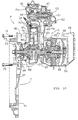
- Fig. 3 is a sectional view taken on line 3-3 of Fig. 2.
- Fig. 4 is a view seen along line 4-4 of Fig. 3.
- Fig. 5 is a sectional view taken on line 5-5 of Fig. 3.
- Fig. 6 is a sectional view taken on line 6-6 of Fig. 3.
- Fig. 7 is a sectional view, taken on line 7-7 of Fig. 3.
- Fig. 8 is an enlarged view of an essential portion of Fig. 2.
- Fig. 9 is a sectional view taken on line 9-9 of Fig. 8.
- Fig. 10 is a view illustrating the function of the present invention upon assembly of the power unit.
-
- Referring to Figs. 1 and 2, a scooter-type motorcycle V includes a front wheel Wf steered by a
steering handle 11 and a rear wheel Wr driven by a swing-type power unit P. A body frame F of the motorcycle V is divided into three parts, that is, afront frame 12, acenter frame 13, and arear frame 14. Thefront frame 12 is made from an aluminum alloy by casting, and integrally includes ahead pipe 121, adown tube 122, and a stepfloor supporting portion 123. Thecenter frame 13 by means of which the power unit P is vertically swingably supported via apivot 15 is made from an aluminum alloy by casting and is connected to the rear end of thefront frame 12. Therear frame 14 extending rearwardly, upwardly from the power unit P is formed of an annular pipe. Afuel tank 16 is supported on the upper surface of therear frame 14. Ahelmet case 17 is supported on the upper surface of thecenter frame 13. Thehelmet case 17 and thefuel tank 16 are openably/closably covered with acover 19 integrated with aseat 18. - The power unit P includes a water-cooled type single-cylinder/four-cycle engine E with its cylinder directed forwardly of the vehicular body, and a belt-type continuously variable transmission T which is integrally connected to the left side surface of the engine E and extends rearwardly of the vehicular body therefrom. The upper rear surface of the belt-type continuously variable transmission T is connected to the rear end of the
center frame 13 via arear cushion 20. Anair cleaner 21 is supported on the upper surface of the belt-type continuously variable transmission T. Amuffler 22 is supported on the right side surface of the belt-type continuously variable transmission T, and astand 23 is supported on the back surface of the engine E. - As is apparent from Figs. 3 to 5, the engine E is divided along a parting plane P1 extending in the vertical direction along a
crank shaft 31 into afirst engine block 32 and asecond engine block 33. Thefirst engine block 32 constitutes a cylinder block and a half of a crank case, and thesecond engine block 33 constitutes the other half of the crank case. Acylinder head 34 is connected to the front end of thefirst engine block 32 via a parting plane P2, and ahead cover 35 is connected to the front end of thecylinder head 34 via a parting plane P3.A generator cover 36 is connected to the right side surfaces of the first andsecond engine blocks - The belt-type continuously variable transmission T includes a right side
first transmission casing 37 and a left sidesecond transmission casing 38 which are connected to each other via a parting plane P5. The right side surface of a front portion of thefirst transmission casing 37 is connected to the left side surfaces of the first andsecond engine blocks first transmission casing 37 is connected to areducer casing 39 via a parting plane P7. - As shown in Fig. 3, a piston 42 slidably fitted in a cylinder 41 provided in the
first engine block 32 is connected to acrank shaft 31 via a connectingrod 43. Acam shaft 44 is rotatably supported by thecylinder head 34, and intake valves and exhaust valves (not shown) provided in thecylinder head 34 are opened/closed by thecam shaft 44. Atiming chain 45 contained in achain passage 321 provided in thefirst engine block 32 is wound around adrive sprocket 46 provided on thecrank shaft 31 and a drivensprocket 47 provided on thecam shaft 44. Thecam shaft 44 makes one revolution for two revolutions of thecrank shaft 31. - An
ac generator 48 provided on the right side of thecrank shaft 31 is covered with thegenerator cover 36, and aradiator 49 is provided on the right side of thegenerator cover 36. Acooling fan 50 fixed at the right end of thecrank shaft 31 for supplying cooling wind to theradiator 49 is disposed between theac generator 48 and theradiator 49. Athermostat case 52 containing athermostat 51 is connected to the right side surface of thecylinder head 34 via a parting plane P8. Acooling water pump 53 provided at the right end of thecam shaft 44 is contained in a space surrounded by thecylinder head 34 and thethermostat case 52. - A
drive pulley 54 as an input rotational member of the belt-type continuously variable transmission T is provided at the left end of thecrank shaft 31 projecting in the first andsecond transmission casings drive pulley 54 includes a fixedside pulley half 55 fixed on thecrank shaft 31, and a movableside pulley half 56 movable close to or apart from the fixedside pulley half 55. The movableside pulley half 56 is biased toward the fixedside pulley half 55 by acentrifugal weight 57 moved radially outwardly in accordance with the increased rotational number of thecrank shaft 31. - A driven pulley 59 is provided on an
output shaft 58 supported between a rear portion of thefirst transmission casing 37 and thereducer casing 39. The driven pulley 59 includes a fixedside pulley half 60 relatively rotatably supported by theoutput shaft 58, and a movable side pulley half 61 movable close to or apart from the fixedside pulley half 60. The movable pulley half 61 is biased toward the fixedside pulley half 60 by a spring 62. Astarting clutch 63 is provided between thefixed pulley half 60 and theoutput shaft 58. An endless V-belt 64 is wound between thedrive pulley 54 and the driven pulley 59. - An
intermediate shaft 65 and anaxle 66 in parallel to theoutput shaft 58 are supported between thefirst transmission casing 37 and thereducer casing 39. A reduction gear train 67 is provided among theoutput shaft 58, theintermediate shaft 65, and theaxle 66. The rear wheel Wr is provided at the right end of theaxle 66 projecting rightwardly through thereducer casing 39. - The rotation of the
crank shaft 31 of the engine E is transmitted to thedrive pulley 54 as the input member of the belt-type continuously variable transmission T, and is transmitted from thedrive pulley 54 to the rear wheel Wr via the V-belt 64, the driven pulley 59, the startingclutch 63, and the reduction gear train 67. - Upon low speed rotation of the engine E, since the centrifugal force applied to the
centrifugal weight 57 of thedrive pulley 54 is small, the groove width between the fixedside pulley half 60 and the movable side pulley half 61 is reduced by the biasing force of the spring 62 of the driven pulley 59, with a result that the speed change ratio becomes the "LOW" ratio. As the rotational number of thecrank shaft 31 is increased from such a state, the centrifugal force applied to thecentrifugal weight 57 is increased, so that the groove width between the fixedside pulley half 55 and the movableside pulley half 56 of thedrive pulley 54 is reduced and correspondingly the groove width between the fixedside pulley half 60 and the movable side pulley half 61 of the driven pulley 59 is increased. As a result, the speed change ratio is continuously variably changed from the ratio "LOW" to the ratio "TOP". - As is apparent from Figs. 3 and 4, a lower front portion of the
radiator 49 is connected to thethermostat cover 521 by a coolingwater pipe line 71; thethermostat case 52 is connected to thefirst engine block 32 by a coolingwater pipe line 72; and thecylinder head 34 is connected to an upper rear portion of theradiator 49 by a coolingwater pipe line 73. - In a state in which the warming operation of the engine has been completed, cooling water discharged from the cooling
water pump 53 is supplied to a water jacket provided in thefirst engine block 32 and thecylinder head 34 via thethermostat case 52 and the coolingwater pipe line 72. During passing through the water jacket, the cooling water cools the engine E. Then, the cooling water is supplied to theradiator 49 via the coolingwater pipe line 73. During passing through theradiator 49, the temperature of the cooling water is reduced. The cooling water is then returned to the coolingwater pump 53 via the coolingwater pipe line 71 and thethermostat 51. During warming operation of the engine E, that is, when the temperature of the cooling water is low, thethermostat 51 is operated to allow the cooling water to be circulated in the engine E not by way of theradiator 49, so that the temperature of the cooling water is rapidly increased. - In this way, the accessories for cooling the engine such as the
radiator 49, the coolingfan 50, thethermostat 51, the coolingwater pump 53, and the coolingwater pipe lines water pipe lines - In particular, since the belt-type continuously variable transmission T is separable from the engine E, it is possible not only to facilitate the transportation of the engine E and the change in posture of the engine E, but also to make stable the posture of the engine E in such a manner as to allow the accessories to be easily mounted/dismounted, by supporting the engine E while directing downwardly the parting plane P6 to which the belt-type continuously variable transmission T is connected. Since the
timing chain 45 for driving thecam shaft 44 and the coolingwater pump 53 is also disposed on the right side surface of the engine E, thetiming chain 45 can be assembled simultaneously with the assembly of the coolingwater pump 53, to thereby further improve the workability. Further, as compared with the conventional integral structure in which the engine block is not separable from the transmission casing, it is possible not only to miniaturize individual parts and hence to reduce the cost required for the molds, but also to combine a plurality of kinds of engines with a plurality of kinds of transmissions in various manners and hence to improve the general versatility. - The engine block is divided along the axial line of the
crank shaft 31 into the first and second engine blocks 32 and 33, and further the cylinder 41, the piston 42, the connectingrod 43, and thecrank shaft 31 can be previously assembled to thefirst engine block 32 side, and accordingly, it is possible to facilitate the assembly of the engine E. - As is apparent from Fig. 3 and Figs. 5 to 7, the first and second engine blocks 32 and 33 are integrally connected to the
first transmission casing 37 with twobolts 74 and twobolts 75 screwed from thefirst transmission casing 37 side. The heads of the front side twobolts 74 for connecting thefirst transmission casing 37 to thefirst engine block 32 are exposed outside the belt-type continuously variable transmission T. The heads of the rear side twobolts 75 for connecting thefirst transmission casing 37 to thesecond engine block 33 are covered with thesecond transmission casing 38 and are not viewed from the outside of the belt-type continuously variable transmission T. - A circular opening 76 (see Fig. 5) centered at the
crank shaft 31 is formed in the left side surfaces of the first and second engine blocks 32 and 33. A circular opening 77 (see Figs. 6 and 7) centered at thecrank shaft 31 is also formed in thefirst transmission casing 37. When the first and second engine blocks 32 and 33 are connected to thefirst transmission casing 37, anannular seat 78 formed at the peripheral edge of theopening 76 formed in the first and second engine blocks 32 and 33 is brought into contact with anannular seat 79 formed at the peripheral edge of theopening 77 formed into thefirst transmission casing 37 via an annular seal member 80 (see Fig. 3). The diameter of theopening 77 of thefirst transmission casing 37 is slightly larger than the maximum diameter of thedrive pulley 54 of the belt-type continuously variable transmission T, and accordingly, thedrive pulley 54 is allowed to pass through theopening 77 of thefirst transmission casing 37. - Two
bosses 81 and twobosses 82, through which the front side twobolts 74 pass, project from thefirst engine block 32 and thefirst transmission casing 37, respectively. Twobosses 83 and twobosses 84, through which the rear side twobolts 75 pass, project from thesecond engine block 33 and thefirst transmission casing 37, respectively. - Accordingly, when the first and second engine blocks 32 and 33 are connected to the
first transmission casing 37 with the fourbolts bosses bosses first transmission casing 37, respectively. In Figs. 5 and 6, the portions at which the first and second engine blocks 32 and 33 are in contact with thefirst transmission casing 37 are designated by crosshatching. - Spaces S (see Fig. 3) constituting heat insulating air layers are formed between the
seat 78 of the first and second engine blocks 32 and 33 and theseat 79 of thefirst transmission casing 37, which are in contact therewith, and between thebosses bosses first transmission casing 37, which are in contact therewith. By forming the spaces S constituting the heat insulating air layers between the first and second engine blocks 32 and 33 and thefirst transmission casing 37 as described above, it is possible to prevent the heat transfer from the engine E to the belt-type continuously variable transmission T, and hence to ensure the durability of the V-belt 64 being weak against heat without increasing the cooling function of the belt-type continuously variable transmission T so much. - As shown in Fig. 10, upon assembly of the power unit P, the
drive pulley 54 of the belt-type continuously variable transmission T is assembled with thecrank shaft 31 of the engine E previously sub-assembled, and then the first and second engine blocks 32 and 33 are connected to thefirst transmission casing 37 with the fourbolts opening 77 of thefirst transmission casing 37 is larger than the maximum outside diameter of thedrive pulley 54 assembled with thecrank shaft 31, the first and second engine blocks 32 and 33 can be easily connected to thefirst transmission casing 37, to thereby enhance the assembling performance. - As shown in Figs. 8 and 9, a pair of right and left
bolts 92 are supported by thecenter frame 13 viarubber bushes 91, and right and leftlink plates bolts 92. Stopper rubbers 96 are mounted in two box-like stopperrubber supporting members 95 provided on the outer side surface of thelink plate 93 positioned on the left side of the vehicular body. Two receivingplanes center frame 13. The right and leftlink plates rod 97 and thepivot 15. A pair of right and lefthanger brackets 98 projecting forwardly, upwardly from the engine E are supported by thepivot 15 viarubber bushes 99. - A load inputted from the power unit P to the
pivot 15 via the right and lefthanger brackets 98 is absorbed by elastic deformation of therubber bushes 99 for supporting thepivot 15, and is also absorbed by elastic deformation of the stopper rubbers 96 which are pressed on the receivingplanes center frame 13 by swing motion of thelink plates bolts 92. The above load is also absorbed by elastic deformation of therubber bushes 91 for supporting thebolts 92 on thecenter frame 13. - While the embodiment of the present invention will be described in detail, the present invention is not limited thereto, and it is to be understood that many changes in design may be made without departing from the scope of the present invention.
- For example, in the embodiment, description has been made of the swing-type power unit of the motorcycle V; however, the swing-type power unit P of the present invention can be applied to a motor-tricycle. Further, the present invention can be applied not only to the combination of one of a plurality of kinds of the engines E different in specification and one of a plurality of kinds of the belt-type continuously variable transmissions T different in specification, but also to the combination of one kind of the engine E and one kind of the belt-type continuously variable transmission T.
- The invention provides a swing-type power unit integrally including an engine and a transmission, which is capable of facilitating the manufacture, assembly and handling of the engine, and allowing free combination of the engine and transmission thereby enhancing the general versatility thereof.
- To achieve this, a swing-type power unit P integrally includes an engine E and a transmission T for transmitting a drive force of the engine E to a drive wheel Wr, and is swingably supported by a body frame. An engine block is divided into first and second engine blocks 32 and 33 which are disposed on the front and rear sides with a
crank shaft 31 put therebetween, respectively.Casings bolts
Claims (4)
- A swing-type power unit swingably supported by a body frame (F) of a small-sized motorcycle or motor-tricycle, comprising:an engine (E); anda transmission (T) for transmitting a drive force of said engine (E) to a drive wheel (Wr), said transmission (T) being integrally connected to said engine (E);
wherein an engine block (32, 33) for supporting a crank shaft (31) of said engine (E) is separable from a casing (37, 38) of said transmission (T). - A swing-type power unit according to claim 1, wherein said engine block (32, 33) is divided into two parts along a parting plane (P1) including the axial line of said crank shaft (31); anda cylinder block for containing a piston (42) is integrally formed on one of said two parts of said engine block (32, 33).
- A swing-type power unit according to claim 1, wherein an input rotational member (54) of said transmission (T) is provided at one end of said crank shaft (31) supported by said engine block (32, 33); andan opening (77) for allowing said input rotational member (54) to pass therethrough when said engine block (32, 33) is connected to said casing (37, 38) of said transmission (T) is formed in said casing (36, 37).
- A swing-type power unit according to claim 1, wherein said transmission (T) is a belt-type continuously variable transmission; andsaid engine block (32, 33) is integrally connected to said casing (37, 38) of said transmission (T) at connection portions surrounding the outer periphery of said crank shaft (31) with a plurality of bolts (74, 75) in such a manner that spaces (S) constituting heat insulating air layers are formed in said connection portions.
Applications Claiming Priority (2)
| Application Number | Priority Date | Filing Date | Title |
|---|---|---|---|
| JP455699 | 1999-01-11 | ||
| JP11004556A JP2000204960A (en) | 1999-01-11 | 1999-01-11 | Swing type power unit |
Publications (3)
| Publication Number | Publication Date |
|---|---|
| EP1020350A2 true EP1020350A2 (en) | 2000-07-19 |
| EP1020350A3 EP1020350A3 (en) | 2002-01-02 |
| EP1020350B1 EP1020350B1 (en) | 2005-07-20 |
Family
ID=11587332
Family Applications (1)
| Application Number | Title | Priority Date | Filing Date |
|---|---|---|---|
| EP00100362A Expired - Lifetime EP1020350B1 (en) | 1999-01-11 | 2000-01-07 | Swing-type power unit |
Country Status (6)
| Country | Link |
|---|---|
| EP (1) | EP1020350B1 (en) |
| JP (1) | JP2000204960A (en) |
| KR (1) | KR100367974B1 (en) |
| CN (1) | CN1174892C (en) |
| DE (1) | DE60021292T2 (en) |
| TW (1) | TW432157B (en) |
Cited By (5)
| Publication number | Priority date | Publication date | Assignee | Title |
|---|---|---|---|---|
| EP1431097A2 (en) * | 2002-12-20 | 2004-06-23 | HONDA MOTOR CO., Ltd. | Vehicular power transmission mechanism |
| EP1201535A3 (en) * | 2000-10-27 | 2005-01-05 | Yamaha Hatsudoki Kabushiki Kaisha | Vehicle transmission |
| EP1498642A1 (en) * | 2002-04-08 | 2005-01-19 | Yamaha Hatsudoki Kabushiki Kaisha | Engine |
| EP1798395A1 (en) * | 2005-12-14 | 2007-06-20 | Kwang Yang Motor Co., Ltd. | Vehicle transmission |
| EP3524502A1 (en) * | 2018-02-09 | 2019-08-14 | Honda Motor Co., Ltd. | Saddle riding vehicle |
Families Citing this family (4)
| Publication number | Priority date | Publication date | Assignee | Title |
|---|---|---|---|---|
| JP4897905B2 (en) * | 2010-04-15 | 2012-03-14 | 本田技研工業株式会社 | Motorcycle |
| JP5695471B2 (en) * | 2011-03-31 | 2015-04-08 | 本田技研工業株式会社 | Electric vehicle |
| TWI739347B (en) | 2020-03-17 | 2021-09-11 | 光陽工業股份有限公司 | locomotive |
| TWM610118U (en) * | 2020-06-22 | 2021-04-11 | 光陽工業股份有限公司 | Straddle-type vehicle with liquid cooling device |
Citations (1)
| Publication number | Priority date | Publication date | Assignee | Title |
|---|---|---|---|---|
| JP2649179B2 (en) | 1988-12-30 | 1997-09-03 | ヤマハ発動機株式会社 | Air-liquid cooling engine |
Family Cites Families (2)
| Publication number | Priority date | Publication date | Assignee | Title |
|---|---|---|---|---|
| JP3183921B2 (en) * | 1991-10-14 | 2001-07-09 | ヤマハ発動機株式会社 | Power unit for electric motorcycle |
| JP3480584B2 (en) * | 1993-12-07 | 2003-12-22 | 本田技研工業株式会社 | Cooling structure of vehicle power unit |
-
1999
- 1999-01-11 JP JP11004556A patent/JP2000204960A/en active Pending
- 1999-12-29 TW TW088123229A patent/TW432157B/en not_active IP Right Cessation
-
2000
- 2000-01-07 DE DE60021292T patent/DE60021292T2/en not_active Expired - Lifetime
- 2000-01-07 EP EP00100362A patent/EP1020350B1/en not_active Expired - Lifetime
- 2000-01-11 CN CNB001009532A patent/CN1174892C/en not_active Expired - Fee Related
- 2000-01-11 KR KR10-2000-0001210A patent/KR100367974B1/en not_active IP Right Cessation
Patent Citations (1)
| Publication number | Priority date | Publication date | Assignee | Title |
|---|---|---|---|---|
| JP2649179B2 (en) | 1988-12-30 | 1997-09-03 | ヤマハ発動機株式会社 | Air-liquid cooling engine |
Cited By (11)
| Publication number | Priority date | Publication date | Assignee | Title |
|---|---|---|---|---|
| EP1201535A3 (en) * | 2000-10-27 | 2005-01-05 | Yamaha Hatsudoki Kabushiki Kaisha | Vehicle transmission |
| EP1498642A1 (en) * | 2002-04-08 | 2005-01-19 | Yamaha Hatsudoki Kabushiki Kaisha | Engine |
| EP1498642A4 (en) * | 2002-04-08 | 2006-11-02 | Yamaha Motor Co Ltd | Engine |
| US7316626B2 (en) | 2002-04-08 | 2008-01-08 | Yamaha Hatsudoki Kabushiki Kaisha | Engine |
| EP2113689A3 (en) * | 2002-04-08 | 2009-12-16 | Yamaha Hatsudoki Kabushiki Kaisha | Engine with CVT and small distance pulleys |
| US8202181B2 (en) | 2002-04-08 | 2012-06-19 | Yamaha Hatsudoki Kabushiki Kaisha | Engine |
| EP1431097A2 (en) * | 2002-12-20 | 2004-06-23 | HONDA MOTOR CO., Ltd. | Vehicular power transmission mechanism |
| EP1431097A3 (en) * | 2002-12-20 | 2004-09-15 | HONDA MOTOR CO., Ltd. | Vehicular power transmission mechanism |
| US7287621B2 (en) | 2002-12-20 | 2007-10-30 | Honda Motor Co., Ltd. | Vehicular power transmission mechanism |
| EP1798395A1 (en) * | 2005-12-14 | 2007-06-20 | Kwang Yang Motor Co., Ltd. | Vehicle transmission |
| EP3524502A1 (en) * | 2018-02-09 | 2019-08-14 | Honda Motor Co., Ltd. | Saddle riding vehicle |
Also Published As
| Publication number | Publication date |
|---|---|
| JP2000204960A (en) | 2000-07-25 |
| DE60021292T2 (en) | 2006-01-05 |
| KR20000063966A (en) | 2000-11-06 |
| EP1020350A3 (en) | 2002-01-02 |
| CN1260294A (en) | 2000-07-19 |
| DE60021292D1 (en) | 2005-08-25 |
| TW432157B (en) | 2001-05-01 |
| CN1174892C (en) | 2004-11-10 |
| KR100367974B1 (en) | 2003-01-14 |
| EP1020350B1 (en) | 2005-07-20 |
Similar Documents
| Publication | Publication Date | Title |
|---|---|---|
| JP3696508B2 (en) | Radiator device for vehicle | |
| JP4732375B2 (en) | Forced air-cooled internal combustion engine | |
| EP1020351B1 (en) | Swing-type power unit | |
| EP1020350B1 (en) | Swing-type power unit | |
| JP3812754B2 (en) | Cooling water pump mounting structure for water-cooled internal combustion engine for small vehicles | |
| US6708652B2 (en) | Engine valve timing apparatus | |
| JP2004360520A (en) | Four-stroke engine equipped with belt-type continuously variable transmission mechanism | |
| JP3819700B2 (en) | Radiator device for vehicle | |
| JP3777298B2 (en) | Radiator mounting structure in vehicles | |
| JP2004084551A (en) | Drive unit for riding vehicle | |
| JP4719778B2 (en) | Swing type power unit | |
| JP3652696B2 (en) | Radiator device for vehicle | |
| JP2000344168A (en) | Filler neck fitting structure for radiator in motorcycle | |
| JP3388244B2 (en) | Motorcycles and tricycles | |
| WO2005008100A1 (en) | Engine for saddle-riding type vehicle and saddle-riding type vehicle having the same | |
| JP4036409B2 (en) | Swing type power unit | |
| JP3828883B2 (en) | Power unit | |
| JP4244673B2 (en) | Snowmobile engine structure | |
| JP3686077B2 (en) | Radiator device for vehicle | |
| JP2000345854A (en) | Supporting structure for crankshaft | |
| JP4084484B2 (en) | Swing type power unit | |
| JP2004044599A5 (en) | ||
| JP2001241358A (en) | Oil pan structure of four-cycle engine for motor scooter | |
| JP2004353482A (en) | Cooling structure of engine for snowmobile |
Legal Events
| Date | Code | Title | Description |
|---|---|---|---|
| PUAI | Public reference made under article 153(3) epc to a published international application that has entered the european phase |
Free format text: ORIGINAL CODE: 0009012 |
|
| AK | Designated contracting states |
Kind code of ref document: A2 Designated state(s): AT BE CH CY DE DK ES FI FR GB GR IE IT LI LU MC NL PT SE Kind code of ref document: A2 Designated state(s): DE FR IT |
|
| AX | Request for extension of the european patent |
Free format text: AL;LT;LV;MK;RO;SI |
|
| PUAL | Search report despatched |
Free format text: ORIGINAL CODE: 0009013 |
|
| AK | Designated contracting states |
Kind code of ref document: A3 Designated state(s): AT BE CH CY DE DK ES FI FR GB GR IE IT LI LU MC NL PT SE |
|
| AX | Request for extension of the european patent |
Free format text: AL;LT;LV;MK;RO;SI |
|
| 17P | Request for examination filed |
Effective date: 20020318 |
|
| AKX | Designation fees paid |
Free format text: DE FR IT |
|
| GRAP | Despatch of communication of intention to grant a patent |
Free format text: ORIGINAL CODE: EPIDOSNIGR1 |
|
| GRAS | Grant fee paid |
Free format text: ORIGINAL CODE: EPIDOSNIGR3 |
|
| GRAA | (expected) grant |
Free format text: ORIGINAL CODE: 0009210 |
|
| AK | Designated contracting states |
Kind code of ref document: B1 Designated state(s): DE FR IT |
|
| REF | Corresponds to: |
Ref document number: 60021292 Country of ref document: DE Date of ref document: 20050825 Kind code of ref document: P |
|
| ET | Fr: translation filed | ||
| PLBE | No opposition filed within time limit |
Free format text: ORIGINAL CODE: 0009261 |
|
| STAA | Information on the status of an ep patent application or granted ep patent |
Free format text: STATUS: NO OPPOSITION FILED WITHIN TIME LIMIT |
|
| 26N | No opposition filed |
Effective date: 20060421 |
|
| PGFP | Annual fee paid to national office [announced via postgrant information from national office to epo] |
Ref country code: DE Payment date: 20110105 Year of fee payment: 12 Ref country code: IT Payment date: 20110115 Year of fee payment: 12 Ref country code: FR Payment date: 20110128 Year of fee payment: 12 |
|
| REG | Reference to a national code |
Ref country code: FR Ref legal event code: ST Effective date: 20120928 |
|
| PG25 | Lapsed in a contracting state [announced via postgrant information from national office to epo] |
Ref country code: DE Free format text: LAPSE BECAUSE OF NON-PAYMENT OF DUE FEES Effective date: 20120801 |
|
| REG | Reference to a national code |
Ref country code: DE Ref legal event code: R119 Ref document number: 60021292 Country of ref document: DE Effective date: 20120801 |
|
| PG25 | Lapsed in a contracting state [announced via postgrant information from national office to epo] |
Ref country code: IT Free format text: LAPSE BECAUSE OF NON-PAYMENT OF DUE FEES Effective date: 20120107 |
|
| PG25 | Lapsed in a contracting state [announced via postgrant information from national office to epo] |
Ref country code: FR Free format text: LAPSE BECAUSE OF NON-PAYMENT OF DUE FEES Effective date: 20120131 |