EP1020296B1 - Power transmission switching device - Google Patents
Power transmission switching device Download PDFInfo
- Publication number
- EP1020296B1 EP1020296B1 EP00100164A EP00100164A EP1020296B1 EP 1020296 B1 EP1020296 B1 EP 1020296B1 EP 00100164 A EP00100164 A EP 00100164A EP 00100164 A EP00100164 A EP 00100164A EP 1020296 B1 EP1020296 B1 EP 1020296B1
- Authority
- EP
- European Patent Office
- Prior art keywords
- drive transmission
- gear
- rocking lever
- locking means
- fitted
- Prior art date
- Legal status (The legal status is an assumption and is not a legal conclusion. Google has not performed a legal analysis and makes no representation as to the accuracy of the status listed.)
- Expired - Lifetime
Links
- 230000005540 biological transmission Effects 0.000 title claims abstract description 262
- 239000011435 rock Substances 0.000 claims abstract description 14
- 230000007246 mechanism Effects 0.000 claims abstract description 7
- 230000002093 peripheral effect Effects 0.000 claims description 26
- 238000007599 discharging Methods 0.000 claims description 11
- 230000001105 regulatory effect Effects 0.000 claims description 2
- 230000006870 function Effects 0.000 description 4
- 230000000694 effects Effects 0.000 description 3
- 238000007639 printing Methods 0.000 description 3
- 238000011084 recovery Methods 0.000 description 2
- 238000005096 rolling process Methods 0.000 description 2
- 241000424063 Genypterus tigerinus Species 0.000 description 1
- 238000006073 displacement reaction Methods 0.000 description 1
- 238000011010 flushing procedure Methods 0.000 description 1
- 238000007641 inkjet printing Methods 0.000 description 1
- 238000000926 separation method Methods 0.000 description 1
Images



Classifications
-
- B—PERFORMING OPERATIONS; TRANSPORTING
- B41—PRINTING; LINING MACHINES; TYPEWRITERS; STAMPS
- B41J—TYPEWRITERS; SELECTIVE PRINTING MECHANISMS, i.e. MECHANISMS PRINTING OTHERWISE THAN FROM A FORME; CORRECTION OF TYPOGRAPHICAL ERRORS
- B41J23/00—Power drives for actions or mechanisms
- B41J23/02—Mechanical power drives
- B41J23/025—Mechanical power drives using a single or common power source for two or more functions
-
- F—MECHANICAL ENGINEERING; LIGHTING; HEATING; WEAPONS; BLASTING
- F16—ENGINEERING ELEMENTS AND UNITS; GENERAL MEASURES FOR PRODUCING AND MAINTAINING EFFECTIVE FUNCTIONING OF MACHINES OR INSTALLATIONS; THERMAL INSULATION IN GENERAL
- F16H—GEARING
- F16H37/00—Combinations of mechanical gearings, not provided for in groups F16H1/00 - F16H35/00
- F16H37/02—Combinations of mechanical gearings, not provided for in groups F16H1/00 - F16H35/00 comprising essentially only toothed or friction gearings
- F16H37/06—Combinations of mechanical gearings, not provided for in groups F16H1/00 - F16H35/00 comprising essentially only toothed or friction gearings with a plurality of driving or driven shafts; with arrangements for dividing torque between two or more intermediate shafts
- F16H37/065—Combinations of mechanical gearings, not provided for in groups F16H1/00 - F16H35/00 comprising essentially only toothed or friction gearings with a plurality of driving or driven shafts; with arrangements for dividing torque between two or more intermediate shafts with a plurality of driving or driven shafts
Definitions
- the present invention relates to a power transmission switching device for selectively switching two drive transmission systems and transmitting driving force from one driving source to the selected drive transmission system, comprising a locking device for securely locking the engagement of gears in the selected drive transmission system; and a recording apparatus provided with the power transmission switching device for individually driving the two drive transmission systems by one driving source.
- EP 0659 571 A discloses a device according to the preamble of claim 1.
- a power transmission switching device may be provided halfway to the driven systems to switch the transmission of the driving force.
- a driving gear having a long dimension in an axial direction is provided on the side of a driving source, a first driven gear and a second driven gear respectively connected to different drive units are provided on the side of driven transmission mechanisms and further, a slide gear which is always engaged with the driving gear and can be slid in the axial direction of the driving gear is provided between the driving gear and the first driven gear or the second driven gear.
- a gear train for a paper supply roller of a printer and a gear train for a paper feeding roller are switched by a switching device as disclosed in Japanese published unexamined patent applications Hei. 10-129057 and Hei. 10-129895.
- the above switching device operates a switching lever utilizing the movement of a carriage to a home position to execute the connection and the release of the connection of gear trains.
- a first object of the present invention is to provide a power transmission switching device provided with relatively simple and compact structure including a mechanism for selectively switching two power transmission systems by one driving source.
- a second object of the present invention is to provide a miniaturized recording apparatus including a power transmission switching device the structure of which is simple and compact for individually driving two drive transmission systems by one driving source.
- a power transmission switching device comprises the features of claim 1.
- driving force from the driving source can be selectively transmitted to the first and second drive transmission systems by rolling the planet gear between the first drive transmission gear of the first drive transmission system and the first drive transmission gear of the second drive transmission system. If the planet gear is rotated clockwise and counterclockwise, that is, if it is normally and reversely rotated, the planet gear is also never separated from the first drive transmission gear of each drive transmission system by locking the rocking lever by the above locking means. Therefore, gears are prevented from being separated and a situation that all teeth are not engaged is prevented from occurring.
- another power transmission switching device comprises the features of claim 2.
- the rocking lever locking means disclosed in Claim 1 and the rocking lever holding means disclosed in Claim 2 can respectively execute the above locking operation and the above operation for an advance and backing both in a direction along the rocked face (the rolled face) of the rocking lever and in a direction perpendicular to the above direction. In either direction, only the displacement of the planet gear on the rocked face of the rocking lever and the rocking lever occurs.
- the above rocking lever is supported by a shaft which is the same or parallel as/to the above drive shaft so that the rocking lever can be rocked and has a peripheral margin equivalent to a part of a circumference, and the above locking means or the rocking lever holding means can be fitted to a part of the peripheral margin of the rockling lever in a state that the above planet gear is engaged with either of the above two drive transmission gears to regulate the rock of the rocking lever.
- the rocking lever is supported by a shaft which is the same or parallel as/to the drive shaft so that the rocking lever can be rocked and as the rocking lever is rocked, the peripheral margin of the planet gear is moved, drawing an arc-shaped locus.
- the above locking means or the rocking lever holding means is fitted to a part of the peripheral margin on the way of a locus of the movement on the peripheral margin in a state that the planet gear is engaged with either of the two drive transmission gears and locks the position of the planet gear attached to the rocking lever.
- the above rocking lever is supported by a shaft which is the same or parallel as/to the above drive shaft so that the rocking lever can be rocked, its free end functions as a fitting part, and the above locking means or the rocking lever holding means is fitted to the above fitting part in a state that the planet gear is engaged with either of the two drive transmission gears to regulate the rock of the rocking lever.
- the structure of the rocking lever is different from that of the first mentioned embodiment, however, the action and effect are common.
- the above power transmission switching device is further provided with a sun gear engaged with the drive shaft of the driving source and the planet gear revolves around a part of the periphery of the sun gear.
- the sun gear is rotated by the rotation of the drive shaft and as the sun gear is rotated, the planet gear revolves around the sun gear until the planet gear is engaged with the first drive transmission gear of one drive transmission system. Also similarly, the planet gear revolves around the sun gear in the reverse direction by reversely rotating the drive shaft until the planet gear is engaged with the first drive transmission gear of the other drive transmission system.
- the above first drive transmission system is connected to a pump for discharging ink from an ink storage tank and for recovering the jetting power of an ink-jet printer.
- the pump sucks ink and when the first drive transmission gear is reversely rotated, the operation for sucking ink of the pump is stopped or the crush of a tube built in the pump by a pressing ember can be released.
- the above second drive transmission system is connected to a paper feeding roller of a printer.
- the normal rotation and the reverse rotation of the paper feeding roller of a printer can be controlled and a state in which paper is fed can be precisely adjusted.
- the above driving source, at least the first drive transmission gear of the above first drive transmission system, at least the first drive transmission gear of the above second drive transmission system, the above rocking lever, the above planet gear and the above locking means or the above rocking lever holding means are united. According to the above configuration, assembly work is completed in a short time only by building the united members as they are in a device for the power transmission switching device to be built.
- the power transmission switching device may comprise one driving source.
- the structure is simplified and unnecessary roll can be securely prevented in a state that the planet gear is engaged with either of the two drive transmission gears. Therefore, even if the first and second drive transmission systems are connected to a drive unit normally and reversely rotated, gears are prevented from being separated and a situation that all teeth are not engaged is prevented from occurring.
- a fitted part may be formed in the above rocking lever, at least one flat side may be formed in a fitting part fitted to the above fitted part of the above locking means, and a flat side which can come in contact with the above flat side may be formed in the fitted part of the rocking lever.
- the flat side of the fitting part formed in the above locking means comes in contact with the flat side of the fitted part and securely locks the rock of the rocking lever.
- each fitted part is preferably, formed at both ends of the peripheral margin of the rocking lever and two opposite flat sides which can come in contact with the flat side of each fitted part are formed in the fitting part of the locking means.
- a flat lower surface is formed in the fitting part of the above locking means and a fitted surface which can come in contact with the lower surface of the fitting part is formed in the above fitted part.
- the above locking means is fitted into the fitted part by touching the flat lower surface of the fitting part of the locking means to the fitted surface of the fitted part and a securer lock can be realized.
- the above rocking lever is supported by a shaft which is the same or parallel as/to the above drive shaft so that the rocking lever can be rocked and the peripheral margin of the rocking lever is formed in the shape of an arc.
- the fitting part of the above locking means is always pressed on the side of the fitted part and the released of the fitting of the fitting part from the fitted part is operated by a solenoid.
- the above rocking lever is supported by a shaft which is the same or parallel as/to the above drive shaft so that the rocking lever can be rocked, its free end functions as a fitting part and the above locking means can be fitted into the fitted part in a state that the above planet gear is engaged with either of the above two drive transmission gears to regulate the rock of the rocking lever.
- the above locking means is provided with a lock pin which can be advanced and backed in a direction perpendicular to a direction in which the rocking lever is rocked by external force and is formed so that the roll of the rocking lever is regulated by the above advance and backing of the lock pin in a state that the above planet gear is engaged with either of the above two drive transmission gears.
- a recording apparatus of the present invention is provided with a power transmission switching device as claimed in claim 1.
- driving force from the driving source can be individually transmitted to the first drive transmission system and the second drive transmission system by rocking the rocking gear between the first drive transmission gear of the first drive transmission system and the first drive transmission gear of the second drive transmission system.
- the structure of the power transmission switching device for individually driving two driven units by one driving source can be simplified and made compact and the whole recording apparatus can be miniaturized.
- the switching member is never separated from the first drive transmission gear of each drive transmission system by locking the switching member by the locking means even if the rocking gear is rotated clockwise and counterclockwise, that is, is normally and reversely rotated. Therefore, a recording apparatus free of separation between gears and disengagement can be realized.
- the above switching member can be rocked using the base on the side of the above drive shaft as a fulcrum, has a part of a circumference as its peripheral margin and the above locking means can be fitted into a part of the peripheral margin of the switching member.
- the peripheral margin of the rocking gear moves, drawing an arc-shaped locus.
- the above locking means is fitted into a part of the peripheral margin on the way of the locus on which the peripheral margin moves and locks the position of the rocking gear attached to the switching member.
- the above power transmission switching device is provided with a sun gear engaged with the drive shaft of the above driving source and the above rocking gear is a planet gear which revolves around a part of the periphery of the sun gear.
- the sun gear is rotated by the rotation of the drive shaft and as the sun gear is rotated, the rocking gear revolves around the sun gear as a planet gear until the rocking gear is engaged with the first drive transmission gear of one drive transmission system.
- the rocking gear revolves around the sun gear in a reverse direction by reversely rotating the drive shaft until the rocking gear is engaged with the first drive transmission gear of the other drive transmission system.
- the above first drive transmission system is connected to a pump for discharging ink from an ink storage tank for jetting power recovery operation of an ink-jet printer.
- the pump sucks ink and when the first drive transmission gear is reversely rotated, the sucking operation of the pump is stopped or the crush of a tube built in the pump by a pressing member can be released.
- trouble by the crush of the tube in the above recording apparatus can be prevented from being caused.
- the second drive transmission system is connected to a paper feeding roller of a printer.
- the normal rotation and the reverse rotation of the paper feeding roller of a printer can be controlled and hereby, a paper fed state in the above recording apparatus can be precisely adjusted.
- the above locking means is constituted so that it can be fitted into a fitted part formed in the above switching member, at least one flat side is formed in the locking means and a flat side which can come in contact with the flat side of the locking means is formed in the fitted part of the switching member.
- the whole flat side of the above locking means comes in contact with the flat side of the fitted part and can securely lock the rock of the switching member.
- each fitted part is formed at both ends of the peripheral margin of the above switching member and two opposite flat sides which can respectively come in contact with the flat side of each fitted part are formed in the above locking means.
- a flat lower surface is formed in the above locking means and a fitted surface which can come in contact with the lower surface of the above locking means is formed in the above fitted part.
- the above locking means is always pressed on the side of the fitted part and the release of the fitting of the locking means from the fitted part is operated by a solenoid.
- the above driving source, at least the first drive transmission gear of the above first drive transmission system, at least the first drive transmission gear of the above second drive transmission system, the above switching member, the above rocking gear, the above sun gear and the above locking means are united to be the above power transmission switching device. According to the above configuration, assembly work is completed in a short time by only assembling the united power transmission switching device as it is in the recording apparatus.
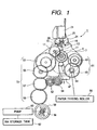
- Fig. 1 is a front view showing a part of a drive transmission system in which a power transmission switching device 1 equivalent to an embodiment of the present invention is built
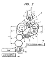
- Fig. 2 is a front view showing a state that the power transmission switching device according to the present invention is connected to a second drive transmission system
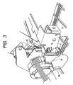
- Fig. 3 is a perspective view showing the main part viewed from the side of a motor (a driving source) in a state that the above power transmission switching device is built in an ink-jet printer which is a recording apparatus
- Fig. 1 is a front view showing a part of a drive transmission system in which a power transmission switching device 1 equivalent to an embodiment of the present invention is built
- Fig. 2 is a front view showing a state that the power transmission switching device according to the present invention is connected to a second drive transmission system
- Fig. 3 is a perspective view showing the main part viewed from the side of a motor (a driving source) in a state that the above power transmission switching device is built in an ink-jet printer which is
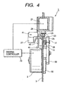
- FIG. 4 is a side view viewed from the side of a first drive transmission system of the power transmission switching device according to the present invention and shows a state that a fitting projection is fitted into a fitting cut-out.
- Fig. 5 is a side view viewed from the side of the first drive transmission system of the power transmission switching device according to the present invention and shows a state that a triggering solenoid is operated and lock by the fitting projection is released.
- Fig. 6 shows a state immediately before the fitting projection is fitted into the fitting cut-out that a rocking lever is located on the side of the first drive transmission system
- Fig. 7 shows a state that the rocking lever is located on the side of the first drive transmission system and the fitting projection is fitted into the fitting cut-out
- Fig. 8 shows another embodiment of a fitted part.
- the power transmission switching device 1 is united by assembling various members on a base plate 3. That is, a motor 5 as a power source shown by an alternate long and short dash line in Figs. 1 and 2 is attached in the center on the back side of the base plate 3. A pinion 7 is attached to the output shaft of the motor 5 and a sun gear 9 is engaged with the pinion 7 in this embodiment. The sun gear 9 is attached onto the base plate 3 and inside it, an inside gear 11 is integrated.
- a rocking lever 13 having a rocking shaft common to the rotating shaft of the sun gear 9 is attached between the sun gear 9 and the base plate 3.
- a planet gear 17 is attached in the vicinity of the peripheral margin 15 of the rocking lever 13 and is engaged with the above inside gear 11.
- the rocking lever 13 is shaped like a fan having a central angle of approximately 90° in this embodiment and a fitting cut-out 19 cut out approximately in the shape of a hook is formed at both ends of the peripheral margin 15.
- the peripheral margin 15 of the rocking lever 13 is arc-shaped and in addition, the cross section is formed so that it has a roundish convex shape.
- a fitted part is formed by cutting out both ends of the rocking lever 13, however, as shown in Fig. 8, a concave fitted part 16 may be also formed in a halfway part of the peripheral margin of the rocking lever 13 or a fitted part may be also formed by protruding from the surface of the rocking lever 13 so that the above fitted part is fitted to a fitting part described later though the fitting part is not shown.
- a triggering solenoid 21 which is one element of locking means for locking the rocking lever 13 in the position is attached to the upper part of the base plate 3 and a plunger 25 at the end of which a contact part 23 shown in Figs. 6 and 7 is formed is provided on the side of the lower end of the triggering solenoid 21.
- the plunger 25 is drawn back when the switch of the triggering solenoid 21 is turned on.
- a triggering lever 27 is provided at the back of the plunger 25 and an upper projection 24 and a lower projection 26 are formed on the front end side of the triggering lever 27 so that they respectively hold the contact part 23 of the plunger 25 from the upper part and the lower part.
- a fitting part 28 having such a shape as is fitted into the fitting cut-out 19 of the rocking lever 13 is formed on the lower side of the lower projection 26 as one element of the above locking means.
- a flat side 29 is formed on both sides of the fitting part 28 and when the fitting part 28 is fitted into the fitting cut-out 19, the whole surface of the above side 29 comes in contact with each side 30 of the fitting cut-out 19.
- the whole side of the fitting part 28 can receive the above force even if such force as rocks the rocking lever 13 in a direction shown by an arrow 31 is applied to the rocking lever when the fitting part 28 is fitted into the fitting cut-out 19, the rock of the rocking lever 13 can be securely provided.
- the lower surface 32 of the fitting part 28 is flat and when the fitting part 28 is fitted into the fitting cut-out 19, the whole lower surface 32 comes in contact with the receiving surface 33 of the fitting cut-out 19.
- the fitting part 28 when the fitting part 28 is fitted into the fitting cut-out 19, the fitting part 28 is tightly fitted into the fitting cut-out 19 and is steady in the fitting cut-out 19.
- the rocking lever 13 can be securely fixed.
- the triggering lever 27 is supported so that it can be turned upward and downward with a fulcrum 41 in the center and is always pressed downward in Fig. 4 by the action of a helical spring 45 connected between a spring fitting part 43 of the base plate 3 and the triggering lever 7.
- the planet gear 17 can be selectively connected to a first drive transmission system 51 and a second drive transmission system 61 respectively provided to the right and the left of the base plate 3 with the pinion 7 of the motor in the center when the rocking lever 13 is rocked (rolled) right or left.
- both drive transmission systems 51 and 61 are connected to a drive unit in a printer. These drive transmission systems 51 and 61 will be described below.
- the first drive transmission system 51 provided to the left side of the base plate 3 is connected to a pump 60 which is a driving system tor discharging ink from an ink storage tank 62 for jetting power recovery operation such as so-called flushing. That is, in an ink-jet printer, operation for jetting ink into the ink storage tank 62 is executed every fixed time for a purpose other than printing to maintain ink jetting precision in continuous printing. Ink in the ink storage tank 62 is required to be discharged by the pump 60 before the ink in the tank overflows.
- the first drive transmission system is a system for transmitting driving force for driving such a pump 60 for discharging ink.
- the first drive transmission system 51 is provided with a pump transmission gear 53 which can be engaged with the planet gear 17 (a first drive transmission gear in the first drive transmission system 51), a first intermediate gear 55 engaged with the above pump transmission gear 53, the succeeding second intermediate gear 57 and a third intermediate gear 59.
- the pump transmission gear 53 and the first intermediate gear 55 of them are united as a part of the power transmission switching device 1 and are assembled on the base plate 3.
- the first drive transmission system 51 is formed so that power can be transmitted from the second intermediate gear 57 to a carriage locking lever 47 via two gears 52 and 54, and the lock and the release of a carriage can be switched.
- the second drive transmission system 61 is provided to the right side of the base plate 3 for driving a paper feeding roller 66 and is provided with a transmission gear 63 for an automatic self feeder (ASF) (a first drive transmission gear of the second drive transmission system) which can be engaged with the planet gear 17 and an ASF driving gear 65 engaged with the above gear.
- the ASF driving gear 65 is provided to the shaft 64 of the paper feeding roller.
- the ASF transmission gear 63 is attached to the base plate 3 as a part of the power transmission switching device 1 and is united.
- the motor 5 As the pump for discharging ink 60 and the paper feeding roller 66 respectively connected to these first and second drive transmission systems 51 and 61 both require both normal and reverse driving, the motor 5, the first and second drive transmission systems 51 and 61 are required to be respectively a mechanism that transmits normal and reverse rotation.
- the fitting part 28 which is one element of the locking means plays the role.
- the planet gear 17 receives force that revolves counterclockwise around the sun gear 9 and tries to separate from the ASF gear 63 and therefore, the fitting part 28 is fitted into the fitting cut-out 19 on the left side of the rocking lever 13 to lock so that the rocking lever 13 cannot be rocked.
- the first drive transmission system 51 is a driving system for driving the above pump for discharging ink 60 composed of a tube pump and the second drive transmission system 61 is a driving system for driving the paper feeding roller 66. Operational control shown in these flowcharts is executed by a driving controller 70 shown in Fig. 4.
- the driving controller 70 normally and reversely rotates the paper feeding roller 6 based upon print data sent from an external computer and others, printing execution time and others measured by the printer itself and switches from a state that power is transmitted to the paper feeding roller 66 to a state that power is transmitted to the pump for discharging ink 60 to drive the pump 60.
- the rocking lever 13 is controlled in an initial state in any case so that it is connected to the side of the first drive transmission system 51, that is, to the side of the pump for discharging ink 60.
- a memory EEPROM
- the memory is composed so that the information of whether the rocking lever 13 is in a pump mode or not when the printer is powered off last time is written.
- the rocking lever 13 is normally located on the side of the second drive transmission system 61. Then, initial operation for moving the rocking lever 13 to the side of the first drive transmission system 51 is executed. As in this operation, the fitting part 28 is fitted into the fitting cut-out 19 on the left side of the rocking lever 13, first, the motor 5 is rotated by +n1 steps (+5 steps) in a step S2 so that force for moving the rocking lever 13 to the side of the pump transmission gear 53 acts to avoid the engagement with the fitting cut-out 19 of the fitting part 28. As described above, if the motor 5 is rotated in the above direction, the rotation is represented by '+' and if the motor is rotated in the reverse direction, the rotation is represented by '-'.
- step S3 the motor is rotated by -n1 steps (-5 steps) in a step S3 so that the rocking lever 13 is driven to the side of the ASF transmission gear 63.
- the triggering solenoid 21 is turned on a little later and the lock of the rocking lever 13 is released in a step S4.
- the motor 5 is driven and is rotated by +n2 steps (+65 steps) and the rocking lever 13 is rocked to the side of the pump transmission gear to engage the planet gear 17 with the pump transmission gear 53 in a step S5.
- the triggering solenoid 21 is turned off, the fitting part 28 is fitted into the fitting cut-out 19 by the action of the helical spring 45 and the rocking lever 13 is locked in a step S6.
- substantial movement to the side of the pump transmission gear is finished.
- the side 29 of the fitting part 28 comes in contact with the side 30 of the fitting cut-out 19, the whole lower surface 32 of the fitting part 28 comes in contact with the receiving surface 33 of the fitting cut-out 19 and lock is secured.
- the motor is further rotated by +n3 steps (+15 steps) in the same direction in a step S7.
- the motor is driven in a direction in which the rocking lever 13 is moved to the side of the ASF transmission gear 63 and is rotated by -n4 steps (-110 steps) in all in a step S8.
- the operation (-n4 steps (-110 steps) in the step S8 drives the pump in a reverse direction to the direction in the step S7.
- the motor is rotated by +n5 steps (+30 steps) in a step S9.
- the pump is driven in a reverse direction to the direction in the step S8. It is stored in the above memory that the current mode is a pump mode. Hereby, connection to the side of the pump is completely finished.
- the rocking lever 13 is located on the ASF driving side and is afterward rocked to the pump driving side, however, it is also supposed that the rocking lever 13 is located on the pump driving side differently from the result of the step S1 because of any cause.
- sucking by the pump or the release is performed in all steps and when the motor is rotated only in one direction, a tube in a tube pump may be crushed.
- the total number of steps in the direction of '+' and that of steps in the direction of '-' are set so that they are equal to prevent the above problem that the tube is crushed in such a case from occurring.
- step S11 if the pump for discharging ink is driven, it is verified in a step S11 that the state in the step S10, that is, the current mode is a pump mode, processing proceeds to a step S16, when the motor is driven, driving force is transmitted to the pump 60 via the first drive transmission system 51 and driving in normal and reverse rotation is executed.
- step S16 when the motor is driven, driving force is transmitted to the pump 60 via the first drive transmission system 51 and driving in normal and reverse rotation is executed.
- step S12 is selected in the step S11, the lock of the rocking lever 13 is released, the motor is reversely rotated, the rocking lever 13 is rocked (rolled) on the right side and the planet gear 17 is engaged with the ASF transmission gear 63 in a step S13.
- the number N1 of steps in which the motor is driven is set so that the above switching can be securely performed.
- the triggering solenoid 21 is turned off, the rocking lever 13 is locked in the position in a step S14 and switching to the ASF driving side is completed.
- ASF is driven and the paper feeding roller 66 is normally and reversely rotated.
- the side 29 of the fitting part 28 comes in contact with the side 30 of the fitting cut-out 19
- the whole lower surface 32 of the fitting part 28 comes in contact with the receiving surface 33 of the fitting cut-out 19 and lock is secured.
- a second embodiment of the present invention will be described below.
- the second embodiment is greatly different from the first embodiment in that the lock and the release of a rocking lever are performed utilizing the movement of the carriage of the printer to a position in readiness (a home position (HP)) without using the triggering solenoid 21.
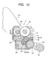
- various members of a power transmission switching device 1 are also assembled on a base plate 103 made of plastic and are united.
- a motor 105 as a power source is attached to the center of the base plate 103 as shown in Fig. 13.
- a pinion 107 is attached to the output shaft 104 of the motor 105 and in this embodiment, the pinion 107 also functions as a sun gear 109.
- a rocking lever 113 shown in Fig. 12 having a rocking shaft common to the rotating shaft (the above output shaft 104) of the sun gear 109 is attached onto the base plate 103.
- a planet gear 117 rolled around of the sun gear 109 is attached to the rocking lever 113.
- the free end of the rocking lever 113 functions as a fitting part 106 and a lock pin 108, which is a rocking lever holding means, instead of the triggering solenoid 21 (a locking means) is constituted so that it can be fitted to the fitting part 106 of the rocking lever 113 in a state in which the above planet gear 117 is engaged with either of a pump transmission gear (a first drive transmission gear) 153 or an ASF transmission gear (a first drive transmission gear) 163 so as to regulate the rock of the rocking lever 113.
- the above lock pin 108 is arranged in a part corresponding to the home position on a line on which the carriage of the printer is moved on the base plate 103.
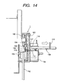
- the lock pin 108 is constituted so that the rocking lever 113 is locked or the lock is released by advancing or backing one end 110 of the lock pin into a hole 111 provided to the base plate 103 in parallel with a direction in which the carriage is moved and in a direction perpendicular to a direction in which the rocking lever 113 is rocked.
- the above locked state of the lock pin 108 is maintained normally by making the above one end 110 pierce the above hole 11 by a spring 114 as shown in Fig. 14.
- a reference number 112 denotes a fitting piece, when the carriage is pressed against the fitting piece 112, the lock pin 108 is pushed back against pressure by the spring 114 and the above locked state is released. That is, the lock and the release of the lock by the lock pin 108 are performed utilizing the movement of the carriage to the home position.
- the rocking lever 113 is rocked (rolled) right and left via the pinion 107 and the sun gear 109 by the driving of the motor 105 and hereby, the planet gear 117 can be selectively connected to the pump transmission gear 153 which is the first drive transmission system and the ASP transmission gear 163 which is the second drive transmission system respectively provided to the right and the left of the base plate 103 with the pinion 107 of the motor 105 in the center.
- a reference number 151 denotes a transmission gear on the side of a pump driving unit and 152 denotes a belt.
- a reference number 123 denotes a paper setting part of an automatic self feeder (ASF).
- Fig. 11 is a flowchart in the second embodiment equivalent to the flowchart in the first embodiment shown in Fig. 10 and steps S21 to S26 correspond to the steps S11 to S16 shown in Fig. 10.
- the steps S22 and S24 are different in that the lock pin 108 driven utilizing the movement of the carriage to the home position (HP) is used, however, they are essentially not different in basic control that the rocking lever 113 is locked in each position and the lock is released.
- driving force from a driving source can be selectively transmitted to the first drive transmission system and the second drive transmission system by rocking (rolling) the planet gear between the first drive transmission gear of the first drive transmission system and the first drive transmission gear of the second drive transmission system.
- the planet gear is never separated from the first drive transmission gear of each drive transmission system by locking the rocking lever by the locking means (e.g. the trigger solenoid) of the rocking lever or rocking lever holding means (e.g. the lock pin 108) even if the planet gear is rotated clockwise and counterclockwise.
- the whole flat side of the above locking means comes in contact with the flat side of the fitted part and the rocking lever can be securely locked.
- the locking means is fitted into the fitted part by making the lower surface of the locking means flat and enabling contact between the surface of the fitted part and the above flat lower surface and securer lock can be realized.
- the flat, compact and reliable power transmission switching device the structure of which is relatively simple can be provided by adopting configuration that the planet gear is attached to the rockable rocking lever and the two drive transmission systems are selectively switched.
- the whole switching device can be flattened by adopting the above configuration, the power transmission switching device can be united. Therefore, assembly work is completed in a short time only by assembling the united switching device as it is.
Landscapes
- Engineering & Computer Science (AREA)
- General Engineering & Computer Science (AREA)
- Mechanical Engineering (AREA)
- Transmission Devices (AREA)
- Ink Jet (AREA)
- Common Mechanisms (AREA)
- Compression Or Coding Systems Of Tv Signals (AREA)
- Diaphragms For Electromechanical Transducers (AREA)
- Dc-Dc Converters (AREA)
- Electrostatic Charge, Transfer And Separation In Electrography (AREA)
Abstract
Description
Claims (27)
- A power transmission switching device (1) provided with a mechanism that two drive transmission systems connected to one driving source (5) are selectively switched, comprising:wherein the first drive transmission gear (53) of said first drive transmission system (51) and the first drive transmission gear (63) of said second drive transmission system (61) are located on both sides of the drive shaft of said driving source (5), and said first (51) and second drive transmission systems (61) are connected to a drive unit normally and reversely rotated.a first drive transmission gear (53) of a first drive transmission system (51); anda first drive transmission gear (63) of a second drive transmission system (61); characterized bya switching member (13) which can be rocked between the first drive transmission gear (53) of said first drive transmission system (51) and the first drive transmission gear (63) of said second drive transmission system (61);a rocking gear (17) attached to said switching member, located between said both drive transmission gears (53, 63), selectively engaged with said both drive transmission gears (53, 63) by the rock of said switching member for transmitting driving force from said driving source (5); andlocking means for locking said switching member in a state that said rocking gear is engaged with either of said two drive transmission gears (53, 63),
- A power transmission switching device (1) as claimed in claim 1, in which the switching member is a rocking lever (13), and the rocking gear is a planet gear (17).
- A power transmission switching device (1) provided with a mechanism that two drive transmission systems connected to one driving source (105) are selectively switched, comprising:wherein the first drive transmission gear (153) of said first drive transmission system (51) and the first drive transmission gear (163) of said second drive transmission system (61) are located on both sides of the drive shaft of said driving source (105), and said first (51) and second drive transmission systems (61) are connected to a drive unit normally and reversely rotated.a first drive transmission gear (153) of a first drive transmission system (51); anda first drive transmission gear (163) of a second drive transmission system (61); characterized bya rocking lever (113) which can be rocked between the first drive transmission gear (153) of said first drive transmission system (51) and the first drive transmission gear (163) of said second drive transmission system (61);a planet gear (117) attached to said rocking lever (113), located between said both drive transmission gears (153, 163), rolled on a locus between said both drive transmission gears (153, 163) and selectively engaged with said both drive transmission gears (153, 163) by the rock of said rocking lever (113) for transmitting driving force from said driving source (105); anda rocking lever holding means that is advanced and backed on a locus on which said rocking lever (113) is rocked to regulate the roll of said planet gear (117) in a state that said planet gear (117) is engaged with either of said two drive transmission gears (153, 163),
- A power transmission switching device (1) according to claim 2, wherein said rocking lever (13) is supported by a shaft which is the same or parallel as/to said drive shaft so that the rocking lever (13) can be rocked and has a part of a circumference as its peripheral margin (15), and said locking means can be fitted into a part of the peripheral margin (15) of said rocking lever (13) to regulate the rock of said rocking lever (13) in a state that said planet gear (17) is engaged with either of said two drive transmission gears (53, 63).
- A power transmission switching device (1) according to claim 2, wherein said rocking lever (13) is supported by a shaft which is the same or parallel as/to said drive shaft so that the rocking lever (13) can be rocked, and its free end is formed as a fitted part (16), and said locking means can be fitted into said fitted part (16) to regulate the rock of said rocking lever (13) in a state that said planet gear (17) is engaged with either of said two drive transmission gears (53, 63).
- A power transmission switching device (1) according to claim 2, further comprising a sun gear (9) engaged with the drive shaft of said driving source (5), wherein said planet gear (17) revolves around a part of the periphery of said sun gear (9).
- A power transmission switching device (1) according to claim 1, wherein said first drive transmission system (51) is connected to a pump (60) for discharging ink from an ink storage tank (62) and for recovering the jetting power of an ink-jet printer.
- A power transmission switching device (1) according to claim 1, wherein said second drive transmission system (61) is connected to a paper feeding roller of a printer.
- A power transmission switching device (1) according to claim 1, wherein said driving source (5), at least the first drive transmission gear (53) of said first drive transmission system (51), at least the first drive transmission gear (63) of said second drive transmission system (61), said rocking lever (13), said planet gear (17) and said locking means are united.
- A power transmission switching device (1) as claimed in claim 3, further comprising said one driving source (105).
- A power transmission switching device (1) according to claim 10, wherein said rocking lever (113) includes a fitted part (16), at least one flat side is formed in a fitting part (106) fitted into said fitted part (16) of said locking means, and a flat side which can come into contact with said flat side is formed in the fitted part (16) of said rocking lever (113).
- A power transmission switching device (1) according to claim 11, wherein each fitted part (16) is formed at both ends of the peripheral margin (15) of said rocking lever (113), and two opposite flat sides which can come into contact with the flat side of said fitted part (16) are formed in the fitting part (106) of said locking means.
- A power transmission switching device (1) according to claim 11, wherein a flat lower surface is formed in the fitting part of said locking means, and a fitted surface which can come in contact with the lower surface of said fitting part (106) is formed in said fitted part (16).
- A power transmission switching device (1) according to claim 11, wherein said rocking lever (113) is supported by a shaft which is the same or parallel as/to said drive shaft so that the rocking lever (113) can be rocked, and the peripheral margin (15) of said rocking lever (113) is formed in the shape of an arc.
- A power transmission switching device (1) according to claim 11, wherein said fitting part (106) of said locking means is always pressed on the side of said fitted part (16), and the release of the fitting of said fitting part (106) from said fitted part (16) is operated by a solenoid (21).
- A power transmission switching device (1) according to claim 10, wherein said rocking lever (113) is supported by a shaft which is the same of parallel as/to said drive shaft so that the rocking lever (113) can be rocked, and its free end is formed as a fitted part (16), and said locking means can be fitted into said fitted part (16) to regulate the rock of said rocking lever (113) in a state that said planet gear (117) is engaged with either of said two drive transmission gears (53, 63).
- A power transmission switching device (1) according to claim 16, wherein said locking means is provided with a lock pin (108) which can be advanced and backed in a direction perpendicular to a direction in which said rocking lever (113) is rocked by external force, and the roll of said rocking lever (113) is regulated by said advance and backing of said lock pin (108) in a state that said planet gear (117) is engaged with either of said two drive transmission gears (53, 63).
- A recording apparatus provided with a power transmission switching device (1) for individually driving two driven systems by one driving source (5), said power transmission switching device (1) comprising the features of claim 1.
- A recording apparatus according to claim 18, wherein said switching member can be rocked using the base on the side of said drive shaft as a fulcrum and has a part of a circumference as its peripheral margin (15), and said locking means can be fitted into a part of the peripheral margin (15) of said switching member.
- A recording apparatus according to claim 18, wherein said power transmission switching device (1) is provided with a sun gear (9) engaged with the drive shaft of said driving source (5), and said rocking gear is a planet gear (17) revolved around a part of the periphery of said sun gear (9).
- A recording apparatus according to claim 18, wherein said first drive transmission system (51) is connected to a pump (60) for discharging ink from an ink storage tank and for recovering the jetting power of an ink-jet printer.
- A recording apparatus according to claim 18, wherein said second drive transmission system (61) is connected to a paper feeding roller for sequentially feeding paper set in the paper feeding part of a printer in a direction of a recording head.
- A recording apparatus according to claim 18, wherein said locking means is constituted so that said locking means can be fitted into a fitted part (16) formed in said switching member, at least one flat side is formed in said locking means; and a flat side which can come in contact with the flat side of said locking means is formed in the fitted part (16) of said switching member.
- A recording apparatus according to claim 23, wherein each fitted part (16) is formed at both ends of the peripheral margin (15) of said switching member, and two opposite flat sides which can come in contact with the flat side of each fitted part (16) are formed in said locking means.
- A recording apparatus according to claim 23, wherein a flat lower surface is formed in said locking means, and a fitted surface which can come in contact with the lower surface of said locking means is formed in said fitted part (16).
- A recording apparatus according to claim 23, wherein said locking means is always pressed on the side of said fitted part (16), and the release of the fitting of said locking means from said fitted part (16) is operated by a solenoid (21).
- A recording apparatus according to claim 18, wherein said driving force, at least the first drive transmission gear (53) of said first drive transmission system (51), at least the first drive transmission gear (163) of said second drive transmission system (61), said switching member, said rocking gear, said sun gear (9) and said locking means are united to be said power transmission switching device (1).
Applications Claiming Priority (10)
| Application Number | Priority Date | Filing Date | Title |
|---|---|---|---|
| JP448299 | 1999-01-11 | ||
| JP432799 | 1999-01-11 | ||
| JP432799 | 1999-01-11 | ||
| JP448299 | 1999-01-11 | ||
| JP8083099A JP3287404B2 (en) | 1999-03-25 | 1999-03-25 | Recording device |
| JP8083099 | 1999-03-25 | ||
| JP11278738A JP2000266156A (en) | 1999-01-11 | 1999-09-30 | Power transmission switching device |
| JP27873899 | 1999-09-30 | ||
| JP27873399 | 1999-09-30 | ||
| JP11278733A JP2000266155A (en) | 1999-01-11 | 1999-09-30 | Locking device for planetary lever in power transmission switching device |
Publications (3)
| Publication Number | Publication Date |
|---|---|
| EP1020296A2 EP1020296A2 (en) | 2000-07-19 |
| EP1020296A3 EP1020296A3 (en) | 2001-01-03 |
| EP1020296B1 true EP1020296B1 (en) | 2005-09-07 |
Family
ID=27518475
Family Applications (1)
| Application Number | Title | Priority Date | Filing Date |
|---|---|---|---|
| EP00100164A Expired - Lifetime EP1020296B1 (en) | 1999-01-11 | 2000-01-11 | Power transmission switching device |
Country Status (4)
| Country | Link |
|---|---|
| US (1) | US6367994B2 (en) |
| EP (1) | EP1020296B1 (en) |
| AT (1) | ATE303903T1 (en) |
| DE (1) | DE60022408T2 (en) |
Families Citing this family (12)
| Publication number | Priority date | Publication date | Assignee | Title |
|---|---|---|---|---|
| US6533387B2 (en) * | 2001-04-11 | 2003-03-18 | Agilent Technologies, Inc. | Inkjet printing system using single motor for print media advance and carriage motion |
| CN1270509C (en) * | 2001-09-18 | 2006-08-16 | 佳能株式会社 | Image reading recording apparatus |
| US6890055B2 (en) | 2002-05-31 | 2005-05-10 | Hewlett-Packard Development Company, L.P. | Power transmission arrangement |
| US6732603B1 (en) | 2002-11-20 | 2004-05-11 | Lite-On Technology | Phase rotary disk motor switching module |
| JP4421916B2 (en) * | 2004-02-26 | 2010-02-24 | セイコーインスツル株式会社 | Printer device |
| JP4158790B2 (en) * | 2005-07-12 | 2008-10-01 | ブラザー工業株式会社 | Conveying apparatus and image forming apparatus |
| US7530559B2 (en) * | 2006-04-12 | 2009-05-12 | Hewlett-Packard Development Company, L.P. | Booklet maker |
| US7934784B2 (en) * | 2007-07-31 | 2011-05-03 | Brother Kogyo Kabushiki Kaisha | Image recording apparatus |
| CN101749374B (en) * | 2008-12-19 | 2012-05-09 | 金宝电子工业股份有限公司 | Transmission force switching mechanism for business machines |
| JP5978785B2 (en) | 2012-06-08 | 2016-08-24 | ブラザー工業株式会社 | Image reading apparatus and image forming apparatus |
| JP6056218B2 (en) | 2012-06-29 | 2017-01-11 | ブラザー工業株式会社 | Image reading apparatus and image forming apparatus |
| JP6031919B2 (en) | 2012-09-28 | 2016-11-24 | ブラザー工業株式会社 | Image reading device |
Family Cites Families (14)
| Publication number | Priority date | Publication date | Assignee | Title |
|---|---|---|---|---|
| JPS6199741A (en) | 1984-10-20 | 1986-05-17 | Mitsubishi Heavy Ind Ltd | Differential gear |
| JPS6273977A (en) * | 1985-09-28 | 1987-04-04 | Alps Electric Co Ltd | Thermal transfer printer |
| JPH0757552B2 (en) * | 1985-10-21 | 1995-06-21 | セイコーエプソン株式会社 | Printer carriage mechanism |
| JPH0789638B2 (en) * | 1986-12-11 | 1995-09-27 | 株式会社テック | Facsimile paper feeder |
| DE3732853A1 (en) * | 1987-09-29 | 1989-04-13 | Siemens Ag | DIRECTIONAL SWITCHING DEVICE |
| US5106216A (en) * | 1989-11-22 | 1992-04-21 | Samsung Electronics Co., Ltd. | Device for driving a platen and carriage of a printing machine |
| JP2677717B2 (en) | 1991-03-29 | 1997-11-17 | シャープ株式会社 | Paper transport mechanism of facsimile machine |
| JP2679890B2 (en) * | 1991-04-15 | 1997-11-19 | 株式会社テック | Facsimile machine |
| US5226743A (en) * | 1991-04-16 | 1993-07-13 | Hewlett-Packard Company | Method and apparatus for paper control in a printer |
| EP0526209B1 (en) | 1991-07-31 | 1997-11-05 | Canon Kabushiki Kaisha | Drive transmission mechanism for recording apparatus |
| US5793399A (en) * | 1993-12-27 | 1998-08-11 | Canon Kabushiki Kaisha | Sheet supplying apparatus |
| JPH09169121A (en) | 1995-12-20 | 1997-06-30 | Seiko Epson Corp | Inkjet printer |
| JP3307549B2 (en) | 1996-10-31 | 2002-07-24 | セイコーエプソン株式会社 | Printer paper feed switching mechanism |
| JP3598689B2 (en) | 1996-10-31 | 2004-12-08 | セイコーエプソン株式会社 | Paper feeder |
-
2000
- 2000-01-11 US US09/480,662 patent/US6367994B2/en not_active Expired - Lifetime
- 2000-01-11 AT AT00100164T patent/ATE303903T1/en not_active IP Right Cessation
- 2000-01-11 EP EP00100164A patent/EP1020296B1/en not_active Expired - Lifetime
- 2000-01-11 DE DE60022408T patent/DE60022408T2/en not_active Expired - Lifetime
Also Published As
| Publication number | Publication date |
|---|---|
| US20020018686A1 (en) | 2002-02-14 |
| DE60022408T2 (en) | 2006-06-22 |
| EP1020296A3 (en) | 2001-01-03 |
| DE60022408D1 (en) | 2005-10-13 |
| US6367994B2 (en) | 2002-04-09 |
| EP1020296A2 (en) | 2000-07-19 |
| ATE303903T1 (en) | 2005-09-15 |
Similar Documents
| Publication | Publication Date | Title |
|---|---|---|
| US6367994B2 (en) | Power transmission switching device, rocking lever locking device in power transmission switching device and power transmission switching device-applied recording apparatus | |
| US5222724A (en) | Paper feeder | |
| EP0580431B1 (en) | Paper feeding apparatus for printer | |
| US9181988B2 (en) | Power transmission switching device and recording apparatus | |
| US6164854A (en) | Automatic cutting device apparatus and method including a reversible motor | |
| JPH0317066Y2 (en) | ||
| US4707154A (en) | Printer | |
| JP3287404B2 (en) | Recording device | |
| JPH03158328A (en) | Paper feeding device | |
| EP1372972B1 (en) | Drive mechanism for transaction printer | |
| JP2000266156A (en) | Power transmission switching device | |
| US20050244206A1 (en) | Printer | |
| US4533270A (en) | Printing paper feed releasing device for printers | |
| JPH0626989B2 (en) | Printer paper feeder | |
| JP2000266155A (en) | Locking device for planetary lever in power transmission switching device | |
| JP3307549B2 (en) | Printer paper feed switching mechanism | |
| JP2007313781A (en) | Recording device | |
| JP2000327152A (en) | Image forming device | |
| JP3546762B2 (en) | Line thermal printer | |
| JPS6025776A (en) | Paper feeding device | |
| JPH10337688A (en) | Auto cutter device and printer using the same | |
| JP2558827B2 (en) | Micro printer | |
| JP2008296559A (en) | Tape processing unit | |
| JPH0317065Y2 (en) | ||
| JP3328117B2 (en) | Serial printer and paper supply method for serial printer |
Legal Events
| Date | Code | Title | Description |
|---|---|---|---|
| PUAI | Public reference made under article 153(3) epc to a published international application that has entered the european phase |
Free format text: ORIGINAL CODE: 0009012 |
|
| AK | Designated contracting states |
Kind code of ref document: A2 Designated state(s): AT BE CH CY DE DK ES FI FR GB GR IE IT LI LU MC NL PT SE |
|
| AX | Request for extension of the european patent |
Free format text: AL;LT;LV;MK;RO;SI |
|
| PUAL | Search report despatched |
Free format text: ORIGINAL CODE: 0009013 |
|
| AK | Designated contracting states |
Kind code of ref document: A3 Designated state(s): DE FR GB |
|
| AX | Request for extension of the european patent |
Free format text: AL;LT;LV;MK;RO;SI |
|
| RIC1 | Information provided on ipc code assigned before grant |
Free format text: 7B 41J 23/02 A, 7F 16H 35/14 B |
|
| 17P | Request for examination filed |
Effective date: 20010313 |
|
| AKX | Designation fees paid |
Free format text: AT BE CH CY DE DK ES FI FR GB GR IE IT LI LU MC NL PT SE |
|
| 17Q | First examination report despatched |
Effective date: 20040816 |
|
| GRAP | Despatch of communication of intention to grant a patent |
Free format text: ORIGINAL CODE: EPIDOSNIGR1 |
|
| GRAS | Grant fee paid |
Free format text: ORIGINAL CODE: EPIDOSNIGR3 |
|
| GRAA | (expected) grant |
Free format text: ORIGINAL CODE: 0009210 |
|
| AK | Designated contracting states |
Kind code of ref document: B1 Designated state(s): AT BE CH CY DE DK ES FI FR GB GR IE IT LI LU MC NL PT SE |
|
| PG25 | Lapsed in a contracting state [announced via postgrant information from national office to epo] |
Ref country code: IT Free format text: LAPSE BECAUSE OF FAILURE TO SUBMIT A TRANSLATION OF THE DESCRIPTION OR TO PAY THE FEE WITHIN THE PRE;WARNING: LAPSES OF ITALIAN PATENTS WITH EFFECTIVE DATE BEFORE 2007 MAY HAVE OCCURRED AT ANY TIME BEFORE 2007. THE CORRECT EFFECTIVE DATE MAY BE DIFFERENT FROM THE ONE RECORDED.SCRIBED TIME-LIMIT Effective date: 20050907 Ref country code: AT Free format text: LAPSE BECAUSE OF FAILURE TO SUBMIT A TRANSLATION OF THE DESCRIPTION OR TO PAY THE FEE WITHIN THE PRESCRIBED TIME-LIMIT Effective date: 20050907 Ref country code: LI Free format text: LAPSE BECAUSE OF FAILURE TO SUBMIT A TRANSLATION OF THE DESCRIPTION OR TO PAY THE FEE WITHIN THE PRESCRIBED TIME-LIMIT Effective date: 20050907 Ref country code: BE Free format text: LAPSE BECAUSE OF FAILURE TO SUBMIT A TRANSLATION OF THE DESCRIPTION OR TO PAY THE FEE WITHIN THE PRESCRIBED TIME-LIMIT Effective date: 20050907 Ref country code: CH Free format text: LAPSE BECAUSE OF FAILURE TO SUBMIT A TRANSLATION OF THE DESCRIPTION OR TO PAY THE FEE WITHIN THE PRESCRIBED TIME-LIMIT Effective date: 20050907 Ref country code: FI Free format text: LAPSE BECAUSE OF FAILURE TO SUBMIT A TRANSLATION OF THE DESCRIPTION OR TO PAY THE FEE WITHIN THE PRESCRIBED TIME-LIMIT Effective date: 20050907 Ref country code: NL Free format text: LAPSE BECAUSE OF FAILURE TO SUBMIT A TRANSLATION OF THE DESCRIPTION OR TO PAY THE FEE WITHIN THE PRESCRIBED TIME-LIMIT Effective date: 20050907 |
|
| REG | Reference to a national code |
Ref country code: GB Ref legal event code: FG4D |
|
| REG | Reference to a national code |
Ref country code: CH Ref legal event code: EP |
|
| REG | Reference to a national code |
Ref country code: IE Ref legal event code: FG4D |
|
| REF | Corresponds to: |
Ref document number: 60022408 Country of ref document: DE Date of ref document: 20051013 Kind code of ref document: P |
|
| PG25 | Lapsed in a contracting state [announced via postgrant information from national office to epo] |
Ref country code: GR Free format text: LAPSE BECAUSE OF FAILURE TO SUBMIT A TRANSLATION OF THE DESCRIPTION OR TO PAY THE FEE WITHIN THE PRESCRIBED TIME-LIMIT Effective date: 20051207 Ref country code: SE Free format text: LAPSE BECAUSE OF FAILURE TO SUBMIT A TRANSLATION OF THE DESCRIPTION OR TO PAY THE FEE WITHIN THE PRESCRIBED TIME-LIMIT Effective date: 20051207 Ref country code: DK Free format text: LAPSE BECAUSE OF FAILURE TO SUBMIT A TRANSLATION OF THE DESCRIPTION OR TO PAY THE FEE WITHIN THE PRESCRIBED TIME-LIMIT Effective date: 20051207 |
|
| PG25 | Lapsed in a contracting state [announced via postgrant information from national office to epo] |
Ref country code: IE Free format text: LAPSE BECAUSE OF NON-PAYMENT OF DUE FEES Effective date: 20060111 |
|
| PG25 | Lapsed in a contracting state [announced via postgrant information from national office to epo] |
Ref country code: LU Free format text: LAPSE BECAUSE OF NON-PAYMENT OF DUE FEES Effective date: 20060131 Ref country code: MC Free format text: LAPSE BECAUSE OF NON-PAYMENT OF DUE FEES Effective date: 20060131 |
|
| NLV1 | Nl: lapsed or annulled due to failure to fulfill the requirements of art. 29p and 29m of the patents act | ||
| REG | Reference to a national code |
Ref country code: CH Ref legal event code: PL |
|
| ET | Fr: translation filed | ||
| PLBE | No opposition filed within time limit |
Free format text: ORIGINAL CODE: 0009261 |
|
| STAA | Information on the status of an ep patent application or granted ep patent |
Free format text: STATUS: NO OPPOSITION FILED WITHIN TIME LIMIT |
|
| 26N | No opposition filed |
Effective date: 20060608 |
|
| REG | Reference to a national code |
Ref country code: IE Ref legal event code: MM4A |
|
| PG25 | Lapsed in a contracting state [announced via postgrant information from national office to epo] |
Ref country code: CY Free format text: LAPSE BECAUSE OF FAILURE TO SUBMIT A TRANSLATION OF THE DESCRIPTION OR TO PAY THE FEE WITHIN THE PRESCRIBED TIME-LIMIT Effective date: 20050907 |
|
| PG25 | Lapsed in a contracting state [announced via postgrant information from national office to epo] |
Ref country code: ES Free format text: LAPSE BECAUSE OF NON-PAYMENT OF DUE FEES Effective date: 20060131 |
|
| PGFP | Annual fee paid to national office [announced via postgrant information from national office to epo] |
Ref country code: FR Payment date: 20110128 Year of fee payment: 12 Ref country code: DE Payment date: 20110105 Year of fee payment: 12 |
|
| PGFP | Annual fee paid to national office [announced via postgrant information from national office to epo] |
Ref country code: GB Payment date: 20110105 Year of fee payment: 12 |
|
| PG25 | Lapsed in a contracting state [announced via postgrant information from national office to epo] |
Ref country code: PT Free format text: LAPSE BECAUSE OF FAILURE TO SUBMIT A TRANSLATION OF THE DESCRIPTION OR TO PAY THE FEE WITHIN THE PRESCRIBED TIME-LIMIT Effective date: 20050907 |
|
| GBPC | Gb: european patent ceased through non-payment of renewal fee |
Effective date: 20120111 |
|
| REG | Reference to a national code |
Ref country code: FR Ref legal event code: ST Effective date: 20120928 |
|
| PG25 | Lapsed in a contracting state [announced via postgrant information from national office to epo] |
Ref country code: DE Free format text: LAPSE BECAUSE OF NON-PAYMENT OF DUE FEES Effective date: 20120801 Ref country code: GB Free format text: LAPSE BECAUSE OF NON-PAYMENT OF DUE FEES Effective date: 20120111 |
|
| REG | Reference to a national code |
Ref country code: DE Ref legal event code: R119 Ref document number: 60022408 Country of ref document: DE Effective date: 20120801 |
|
| PG25 | Lapsed in a contracting state [announced via postgrant information from national office to epo] |
Ref country code: FR Free format text: LAPSE BECAUSE OF NON-PAYMENT OF DUE FEES Effective date: 20120131 |