EP1019779B1 - Improved progressive lens - Google Patents
Improved progressive lens Download PDFInfo
- Publication number
- EP1019779B1 EP1019779B1 EP98941160A EP98941160A EP1019779B1 EP 1019779 B1 EP1019779 B1 EP 1019779B1 EP 98941160 A EP98941160 A EP 98941160A EP 98941160 A EP98941160 A EP 98941160A EP 1019779 B1 EP1019779 B1 EP 1019779B1
- Authority
- EP
- European Patent Office
- Prior art keywords
- correction
- lens
- cylinder
- front surface
- series
- Prior art date
- Legal status (The legal status is an assumption and is not a legal conclusion. Google has not performed a legal analysis and makes no representation as to the accuracy of the status listed.)
- Expired - Lifetime
Links
- 230000000750 progressive effect Effects 0.000 title claims description 64
- 238000012937 correction Methods 0.000 claims description 58
- 230000003287 optical effect Effects 0.000 claims description 49
- 238000000034 method Methods 0.000 claims description 19
- 201000009310 astigmatism Diseases 0.000 claims description 12
- 208000001491 myopia Diseases 0.000 claims description 6
- 230000001747 exhibiting effect Effects 0.000 claims 1
- 238000013461 design Methods 0.000 description 12
- 235000012431 wafers Nutrition 0.000 description 11
- 230000006872 improvement Effects 0.000 description 6
- 239000000463 material Substances 0.000 description 4
- 230000004048 modification Effects 0.000 description 4
- 238000012986 modification Methods 0.000 description 4
- 230000004075 alteration Effects 0.000 description 3
- 238000005266 casting Methods 0.000 description 3
- JHQVCQDWGSXTFE-UHFFFAOYSA-N 2-(2-prop-2-enoxycarbonyloxyethoxy)ethyl prop-2-enyl carbonate Chemical compound C=CCOC(=O)OCCOCCOC(=O)OCC=C JHQVCQDWGSXTFE-UHFFFAOYSA-N 0.000 description 2
- 238000004364 calculation method Methods 0.000 description 2
- 239000011521 glass Substances 0.000 description 2
- 238000003475 lamination Methods 0.000 description 2
- 239000000203 mixture Substances 0.000 description 2
- 125000003903 2-propenyl group Chemical group [H]C([*])([H])C([H])=C([H])[H] 0.000 description 1
- KSXJRXNHRYSLLC-UHFFFAOYSA-N 9H-fluorene prop-2-enoic acid Chemical compound OC(=O)C=C.OC(=O)C=C.C1=CC=C2CC3=CC=CC=C3C2=C1 KSXJRXNHRYSLLC-UHFFFAOYSA-N 0.000 description 1
- 229930185605 Bisphenol Natural products 0.000 description 1
- 206010020675 Hypermetropia Diseases 0.000 description 1
- QYKIQEUNHZKYBP-UHFFFAOYSA-N Vinyl ether Chemical class C=COC=C QYKIQEUNHZKYBP-UHFFFAOYSA-N 0.000 description 1
- 150000001252 acrylic acid derivatives Chemical class 0.000 description 1
- -1 aromatic olefins Chemical class 0.000 description 1
- 238000005284 basis set Methods 0.000 description 1
- 230000008901 benefit Effects 0.000 description 1
- IISBACLAFKSPIT-UHFFFAOYSA-N bisphenol A Chemical compound C=1C=C(O)C=CC=1C(C)(C)C1=CC=C(O)C=C1 IISBACLAFKSPIT-UHFFFAOYSA-N 0.000 description 1
- 230000008859 change Effects 0.000 description 1
- 239000002537 cosmetic Substances 0.000 description 1
- 238000011161 development Methods 0.000 description 1
- 125000004386 diacrylate group Chemical group 0.000 description 1
- 230000000694 effects Effects 0.000 description 1
- 150000002170 ethers Chemical class 0.000 description 1
- LYCAIKOWRPUZTN-UHFFFAOYSA-N ethylene glycol Natural products OCCO LYCAIKOWRPUZTN-UHFFFAOYSA-N 0.000 description 1
- 230000004418 eye rotation Effects 0.000 description 1
- WGCNASOHLSPBMP-UHFFFAOYSA-N hydroxyacetaldehyde Natural products OCC=O WGCNASOHLSPBMP-UHFFFAOYSA-N 0.000 description 1
- 238000003384 imaging method Methods 0.000 description 1
- 238000004519 manufacturing process Methods 0.000 description 1
- 239000011159 matrix material Substances 0.000 description 1
- 238000005259 measurement Methods 0.000 description 1
- 150000002734 metacrylic acid derivatives Chemical class 0.000 description 1
- 239000000178 monomer Substances 0.000 description 1
- VZUGBLTVBZJZOE-KRWDZBQOSA-N n-[3-[(4s)-2-amino-1,4-dimethyl-6-oxo-5h-pyrimidin-4-yl]phenyl]-5-chloropyrimidine-2-carboxamide Chemical compound N1=C(N)N(C)C(=O)C[C@@]1(C)C1=CC=CC(NC(=O)C=2N=CC(Cl)=CN=2)=C1 VZUGBLTVBZJZOE-KRWDZBQOSA-N 0.000 description 1
- 229920000515 polycarbonate Polymers 0.000 description 1
- 239000004417 polycarbonate Substances 0.000 description 1
- 229920006295 polythiol Polymers 0.000 description 1
- 230000008569 process Effects 0.000 description 1
- 230000009467 reduction Effects 0.000 description 1
- 230000004044 response Effects 0.000 description 1
- 125000000391 vinyl group Chemical group [H]C([*])=C([H])[H] 0.000 description 1
- 229920002554 vinyl polymer Polymers 0.000 description 1
Images


Classifications
-
- G—PHYSICS
- G02—OPTICS
- G02C—SPECTACLES; SUNGLASSES OR GOGGLES INSOFAR AS THEY HAVE THE SAME FEATURES AS SPECTACLES; CONTACT LENSES
- G02C7/00—Optical parts
- G02C7/02—Lenses; Lens systems ; Methods of designing lenses
- G02C7/06—Lenses; Lens systems ; Methods of designing lenses bifocal; multifocal ; progressive
- G02C7/061—Spectacle lenses with progressively varying focal power
- G02C7/068—Special properties achieved by the combination of the front and back surfaces
-
- G—PHYSICS
- G02—OPTICS
- G02C—SPECTACLES; SUNGLASSES OR GOGGLES INSOFAR AS THEY HAVE THE SAME FEATURES AS SPECTACLES; CONTACT LENSES
- G02C7/00—Optical parts
- G02C7/02—Lenses; Lens systems ; Methods of designing lenses
- G02C7/06—Lenses; Lens systems ; Methods of designing lenses bifocal; multifocal ; progressive
- G02C7/061—Spectacle lenses with progressively varying focal power
-
- G—PHYSICS
- G02—OPTICS
- G02C—SPECTACLES; SUNGLASSES OR GOGGLES INSOFAR AS THEY HAVE THE SAME FEATURES AS SPECTACLES; CONTACT LENSES
- G02C2202/00—Generic optical aspects applicable to one or more of the subgroups of G02C7/00
- G02C2202/08—Series of lenses, lens blanks
Definitions
- the present invention relates to a progressive ophthalmic lens and in particular to the improvement of the progressive lens surface to compensate for cylinder correction applied to the non-progressive surface.
- Progressive lenses are known in the prior art. Progressive lenses are typically designed to have distance, near and intermediate viewing zones where the intermediate zone joins the near and distance zones in a cosmetically acceptable way, such that no discontinuities in the lens are visible to people observing the wearer.
- US Patent Number 5,444,503 discloses a spectacle lens having a multifocal surface and a prescription surface.
- the prescription surface is a general aspheric surface without point and axis symmetry. Of the individual use conditions, at least the dioptric power is considered within an area when determining the geometry of the prescription surface.
- the prescription surface is provided exclusively for generating the dioptric power in the reference points and additionally for eliminating the increase of imaging errors.
- the present invention provides a method of designing an ophthalmic lens element, said lens element including an upper viewing zone providing good optical quality at a predetermined low surface power over a large area of vision; said predetermined power being determined by the wearer's distance prescription, the horizontal fitting position normally being determined by the interpupillary distance of the wearer, and the vertical fitting position normally being determined by the vertical frame midpoint; a lower viewing zone of higher surface power determined by the wearer's near prescription requirements; and a corridor of relatively low astigmatism extending therebetween; the lens element including a front surface and a back surface; wherein the front surface is achieved by providing a base surface function in the form of a progressive lens surface and by minimising a merit function, M, to reduce optical blur and maximise the width of vision in the upper and lower viewing zones of the lens by using finite element methods to solve the corresponding ophthalmic problem and, wherein the back surface includes the cylinder prescription requirements of the wearer during the optical optimisation, resulting in a finite element solution of the required lens surface, the back
- the present invention additionally provides a series of progressive ophthalmic lens elements, the series including, for a given base/add combination, a member having a general progressive lens surface for 0.00D cylinder and four or more members having a progressive lens surface corrected for a cylinder prescription, each member of the series corrected for cylinder prescription including a front surface that includes an upper viewing zone having a surface power suitable for distance vision, a lower viewing zone having a surface power suitable for near vision, and a corridor of relatively low astigmatism connecting the upper and lower viewing zones, the corridor being a part of an intermediate viewing zone having a surface power varying from that of the upper viewing zone to that of the lower viewing zone; and a back surface; wherein the front surface includes at least one correction to improve optical performance of the lens element by compensating for a cylinder correction applied to, or to be applied to, the back surface, the back surface cylinder correction being in the form of a toric component to provide an astigmatic correction, and wherein the front surface includes a general aspheric correction optimised for at least two
- the present invention has identified that in order to satisfy the requirements of various wearers, including for example wearers requiring astigmatic correction, it is necessary to consider the effects of both front and back surfaces in optical performance, and to modify the front surface to improve optical performance in response to, or in anticipation of, the back surface design.
- astigmatic correction we mean the wearer's prescribed cylinder correction and the associated axis of this correction.
- the improvement in optical performance is preferably an optimisation of the optical field of vision of the wearer in one or more of the upper, lower or intermediate viewing zones.
- This improvement, or optimisation may be relative to an idealised lens element with zero cylinder, or may involve the creation of a new modified progressive lens surface.
- optical field of vision we mean a field defined by the boundary at which blur becomes apparent to the wearer.
- the optical field of vision is thus an area or object field viewed from the standpoint of the wearer, in which there is foveal vision with minimal loss of acuity.
- the size of the optical field of vision is influenced by the size of the lens zone, the net magnification in that zone, and the oblique aberration of the lens.
- lens element we mean all forms of individual refractive optical bodies employed in the ophthalmic arts, including, but not limited to, lenses, lens wafers and semi-finished lens blanks requiring further finishing to a particular patient's prescription. Also included are formers used in the manufacture of progressive glass lenses and moulds for the casting of progressive lenses in polymeric material such as the material sold under the trade designation CR39.
- the progressive front surface may be created by taking any suitable conventional progressive surface and modifying it according to an optical optimisation process which considers the cylindrical correction applied to the rear surface.
- the resulting front surface may differ from conventional progressive designs in that the distance and/or near measurement points thereon may not be spherical.
- the ophthalmic lens element may exhibit differing corrections in at least two regions of the progressive front surface, corresponding to the differing prescription requirements in the distance and near regions.
- the front surface correction will at least partially compensate for a range of cylinder prescriptions.
- the front surface correction may vary depending on the axis of the cylinder correction on the back surface.
- the front surface correction may cover a range of axis values, for example -20° to 20°, depending on the degree of optimisation required, or alternatively the design may involve a specific axis and cylinder.
- the front surface correction may vary depending on the distance prescription power, or may cover a range of distance prescription powers. Further still, the front surface correction may vary depending on the addition power.
- a lens corresponding to the single vision prescription case is initially considered and an optimised front surface design created to produce optimal optical performance with a toric back surface.
- the resulting surface may be a generally aspheric. This surface may then be used to replace the base curve of the progressive lens surface to produce a new modified surface, improving the optical performance of the lens for the complete prescription of the wearer
- This method may be highly automated and utilised with any conventional progressive lens front surface to provide the corrections for a range of prescription, addition power, cylinder and axis orientation values.
- the progressive surface may be designed utilising optical optimisation methods from the initial stages of a progressive surface development.
- the optical optimisation methods consist of the minimisation of a blur measure, M, and applying any of the known finite element methods. This may be achieved by using an appropriate back surface for the prescription identified, and then designing a dedicated front surface.
- the optical performance may be optimised for one or more of distance, intermediate, or near zone vision, depending on the prescription needs of the wearer.
- M 4 there are different blur measures used depending upon whether the sample point ⁇ represents a horizontal, vertical, or oblique rotation from the "straight ahead" position.
- This mode may provide some generalisation of the aspheric "minimum tangential error” design strategy.
- the modes M 3 and M 5 represent “minimum cyl error” and “minimum mean power error” strategies respectively.
- optical blur may be measured in a number of ways.
- the back surface may include an atoric component, which provides both the cylindrical correction and a cosmetic advantage.
- a progressive ophthalmic lens element in the form of a front surface wafer for use with a back surface wafer.
- the front surface wafer may have a front lens surface and a spherical back surface suitable for having laminated thereto the back surface wafer.
- the front lens surface of the front lens surface wafer may include an upper viewing zone having a surface power suitable for distance vision, a lower viewing zone having a surface power suitable for near vision, and a corridor of relatively low astigmatism connecting the upper and lower viewing zones, the corridor being part of an intermediate viewing zone having a surface power varying from that of the upper viewing zone to that of the lower viewing zone.
- the back surface wafer may then have a front surface suitable for lamination to the front surface wafer, and a back lens surface.
- the front lens surface of the front surface wafer preferably includes at least one correction to improve optical performance of an ophthalmic lens formed by the lamination of the front and back surface wafers, by at least partially compensating for a cylinder correction applied to, or to be applied to, the back lens surface of the back surface wafer.
- a method of designing an ophthalmic lens element may include the step of providing a first mathematical or numerical representation of a front surface of an optical lens element, where the front surface includes an upper viewing zone having a surface power suitable for distance vision, a lower viewing zone having a surface power suitable for near vision, and a corridor of relatively low astigmatism connecting the upper and lower viewing zones.
- the corridor is thus a part of an intermediate viewing zone having a surface power varying from that of the upper viewing zone to that of the lower viewing zone.
- the method may then include the further step of modifying the representation of the front surface to at least partially adjust for a back lens surface bearing a cylinder correction.
- the method may include providing a mathematical or numerical representation of a front surface of a single vision optical lens element optimised to compensate for a back surface including a toric component, and then replacing the base curve of the front surface with the optimised representation of the single vision front surface to at least partially adjust for the cylinder correction on the back surface.
- the present invention provides a method of designing an ophthalmic lens element such as that described above, the lens element including an upper viewing zone providing good optical quality at a predetermined low surface power over a large area of vision; said predetermined power being determined by the wearer's distance prescription, the horizontal fitting position normally being determined by the interpupillary distance of the wearer, and the vertical fitting position normally being determined by the vertical frame midpoint; a lower viewing zone of higher surface power determined by the wearer's near prescription requirements; and a corridor of relatively low astigmatism extending therebetween; the lens element including a front surface and a back surface; wherein the front surface is achieved by providing a base surface function in the form of a progressive lens surface and by minimising a merit function, M, to reduce optical blur and maximise the width of vision in the upper and lower viewing zones of the lens by using finite element methods to solve the corresponding ophthalmic problem; and wherein the back surface includes the cylinder prescription requirements of the wearer during the optical optimisation, resulting in a finite element solution of the required
- the design requirements for any progressive lens surface may differ based on whether the wearer is a myope, emmetrope, hyperope, or other category of patient, or may differ based on the lens base curve, distance prescription, or the level of addition power required by the wearer.
- the progressive ophthalmic lens element of the present invention may be a member of a series of such elements.
- Such a progressive ophthalmic lens element series may be characterised in that lens elements from different sets having substantially the same addition power, having substantially the same optical field of vision in at least one of the upper and lower viewing zones.
- the progressive design may be provided on a single surface of the lens element.
- the present invention also provides a series of progressive ophthalmic lens elements, the series including, for a given base/add combination, a member having a general progressive lens surface for 0.00D cylinder and four or more members having a progressive lens surface corrected for a cylinder prescription, each member of the series corrected for cylinder prescription including:
- each lens element within a set having an addition power between approximately 0.50 D to 3.50 D has substantially the same optical field of vision in the lower viewing zone for each category of patient.
- progressive lenses where the surface has been optimised for a cylinder axis selected from 0°, 45°, 90° or 135°, exhibit substantial optical performance improvements over the entire range of cylinder axes. It has also been observed that a progressive lens surface optimised for a cylinder correction of -2.50 D results in substantial optical performance improvements when utilised for cases where the cylindrical correction ranges from -1.00 D to -4.00 D when compared with those optimised for the exact cylinder values.
- a preferred example of such a product series includes, for a given base/add combination, a general progressive lens surface for 0.00 D cyl to -0.75 D of cylinder correction regardless of axis and four corrected surfaces used for the cylinder range of -1.00 D to -4.00 D, for axes of 0°, 45°, 90° and 135°.
- the progressive ophthalmic lens element may be formed from glass or a polymeric article.
- the polymeric article where applicable, may be of any suitable type.
- a polycarbonate for example a material of the diallyl glycol carbonate type, may be used.
- the polymeric article may be formed from cross-linkable polymeric casting compositions, for example as described in United States patent 4,912,155 .
- Such cross-linkable polymeric casting compositions may include a diacrylate or dimethacrylate monomer (such as polyoxyalkylene glycol diacrylate or dimethacrylate or a bisphenol fluorene diacrylate or dimethacrylate) and a polymerisable comonomer, e.g. methacrylates, acrylates, vinyls, vinyl ethers, allyls, aromatic olefins, ethers, polythiols and the like.
- a diacrylate or dimethacrylate monomer such as polyoxyalkylene glycol diacrylate or dimethacryl
- Figures 1 and 2 compare a conventional progressive lens and the progressive lens corrected according to the present invention for the -2.50 D cylinder prescription at two cylinder axis orientations, namely 180° and 90° respectively.
- Figure 3 shows a comparison of optical RMS blur contour plots of a conventional progressive lens and a progressive lens optimised for the -2.50 D at 180° of cylinder.
- Figures 3 (a) and 3 (c) show the conventional progressive with values of prescription -2.00 D and -3.00 D of cylinder respectively.
- Figures 3 (b) and 3(d) show the progressive lens in accordance with the present invention for the same prescription values where the front surface is the surface which has been optimised for the -2.50 D at 180° of cylinder. All of the Figures contain contour levels of 0.5 D, 1.0 D, 1.5 D, 2.0 D, 2.5 D etc.
- Figures 1 to 3 demonstrate two examples of the present invention.
- Each of the Figures contains 2 x 2 frames.
- the first column illustrates a conventional progressive lens with a rotationally symmetric base curve.
- the second column shows a progressive lens in accordance with the present invention with a general aspheric base surface.
- the Optical RMS Blur plots consider an object field that varies throughout the lens from infinity for the upper distance viewing zone region to approximately 40 cm in the lower, near viewing zone.
- the wearer could accommodate up to 0.50 D of power error for eye elevations below 10°.
- the distance between the centre of rotation of the eye and the lens back vertex was set to 27 mm and the lens material index was 1.537.
- optimised surface of Column 2 may be achieved either by applying the correction surface or by direct calculation, utilising optical optimisation methods.
- Figures 1 and 2 illustrate lenses of mean through power +4.25 D.
- Figure 1 illustrates a lens with a base curve of 6.85 D and an addition power of 2.00 D.
- Figure 1 (a) illustrates the surface astigmatism of the conventional progressive
- Figure 1 (b) illustrates the surface astigmatism of the progressive surface corrected for the prescription requirements of +5.50 D and a cylinder axis of -2.50 D at 180°.
- Figure 1 (c) and Figure 1 (d) illustrate the RMS Blur that results with the conventional and corrected surfaces respectively for the prescription of +5.50 D and -2.50 D cylinder at 180°.
- Figure 2 illustrates a lens with a base curve of 6.85 D and an addition power of 2.00 D.
- Figure 2 (a) illustrates the surface astigmatism of the conventional progressive, while Figure 2 (b) illustrates the surface astigmatism of the progressive surface corrected for the prescription requirements of +5.50 D and a cylinder axis of -2.50 D at 90°.
- Figure 2 (c) and Figure 2 (d) illustrate the RMS Blur that results with the conventional and corrected surfaces respectively for the prescription of +5.50 D and -2.50 D cylinder at 90°.
- Figure 3 illustrates the gains in optical performance for two cylinder prescriptions deviating from the optimised one.
Description
- The present invention relates to a progressive ophthalmic lens and in particular to the improvement of the progressive lens surface to compensate for cylinder correction applied to the non-progressive surface.
- Numerous progressive lenses are known in the prior art. Progressive lenses are typically designed to have distance, near and intermediate viewing zones where the intermediate zone joins the near and distance zones in a cosmetically acceptable way, such that no discontinuities in the lens are visible to people observing the wearer.
- Significant advances in customising progressive lens design have been disclosed in international patent application
PCT/EP97/00105 . This application describes a series of lens elements where the progressive designs vary depending on whether the wearer is a myope (short-sighted), emmetrope (normal vision) or hyperope (long sighted), whilst maintaining substantially constant the optical field of vision in the near and/or distance zones. - Whilst these designs are a significant advance, they do not vary with the specific optical requirements of the individual wearer. For example, the designs do not vary when an astigmatic correction is introduced to the back surface of the lens.
-
US Patent Number 5,444,503 discloses a spectacle lens having a multifocal surface and a prescription surface. The prescription surface is a general aspheric surface without point and axis symmetry. Of the individual use conditions, at least the dioptric power is considered within an area when determining the geometry of the prescription surface. The prescription surface is provided exclusively for generating the dioptric power in the reference points and additionally for eliminating the increase of imaging errors. - It is an object of the present invention to provide a progressive ophthalmic lens that compensates for optical corrections introduced for individual wearers.
- The present invention provides a method of designing an ophthalmic lens element, said lens element including an upper viewing zone providing good optical quality at a predetermined low surface power over a large area of vision; said predetermined power being determined by the wearer's distance prescription, the horizontal fitting position normally being determined by the interpupillary distance of the wearer, and the vertical fitting position normally being determined by the vertical frame midpoint; a lower viewing zone of higher surface power determined by the wearer's near prescription requirements; and a corridor of relatively low astigmatism extending therebetween; the lens element including a front surface and a back surface; wherein the front surface is achieved by providing a base surface function in the form of a progressive lens surface and by minimising a merit function, M, to reduce optical blur and maximise the width of vision in the upper and lower viewing zones of the lens by using finite element methods to solve the corresponding ophthalmic problem and, wherein the back surface includes the cylinder prescription requirements of the wearer during the optical optimisation, resulting in a finite element solution of the required lens surface, the back surface cylinder correction being in the form of a toric component to provide an astigmatic correction.
- The present invention additionally provides a series of progressive ophthalmic lens elements, the series including, for a given base/add combination, a member having a general progressive lens surface for 0.00D cylinder and four or more members having a progressive lens surface corrected for a cylinder prescription, each member of the series corrected for cylinder prescription including a front surface that includes an upper viewing zone having a surface power suitable for distance vision, a lower viewing zone having a surface power suitable for near vision, and a corridor of relatively low astigmatism connecting the upper and lower viewing zones, the corridor being a part of an intermediate viewing zone having a surface power varying from that of the upper viewing zone to that of the lower viewing zone; and a back surface; wherein the front surface includes at least one correction to improve optical performance of the lens element by compensating for a cylinder correction applied to, or to be applied to, the back surface, the back surface cylinder correction being in the form of a toric component to provide an astigmatic correction, and wherein the front surface includes a general aspheric correction optimised for at least two principal lens meridional directions.
- In this respect, the present invention has identified that in order to satisfy the requirements of various wearers, including for example wearers requiring astigmatic correction, it is necessary to consider the effects of both front and back surfaces in optical performance, and to modify the front surface to improve optical performance in response to, or in anticipation of, the back surface design. By the term "astigmatic correction", we mean the wearer's prescribed cylinder correction and the associated axis of this correction.
- The improvement in optical performance is preferably an optimisation of the optical field of vision of the wearer in one or more of the upper, lower or intermediate viewing zones. This improvement, or optimisation, may be relative to an idealised lens element with zero cylinder, or may involve the creation of a new modified progressive lens surface.
- By the term "optical field of vision" we mean a field defined by the boundary at which blur becomes apparent to the wearer. The optical field of vision is thus an area or object field viewed from the standpoint of the wearer, in which there is foveal vision with minimal loss of acuity. The size of the optical field of vision is influenced by the size of the lens zone, the net magnification in that zone, and the oblique aberration of the lens.
- By the term "lens element" we mean all forms of individual refractive optical bodies employed in the ophthalmic arts, including, but not limited to, lenses, lens wafers and semi-finished lens blanks requiring further finishing to a particular patient's prescription. Also included are formers used in the manufacture of progressive glass lenses and moulds for the casting of progressive lenses in polymeric material such as the material sold under the trade designation CR39.
- In an ophthalmic lens element, the progressive front surface may be created by taking any suitable conventional progressive surface and modifying it according to an optical optimisation process which considers the cylindrical correction applied to the rear surface. The resulting front surface may differ from conventional progressive designs in that the distance and/or near measurement points thereon may not be spherical.
- The ophthalmic lens element may exhibit differing corrections in at least two regions of the progressive front surface, corresponding to the differing prescription requirements in the distance and near regions. In a preferred form, the front surface correction will at least partially compensate for a range of cylinder prescriptions. For example, the front surface correction may vary depending on the axis of the cylinder correction on the back surface. In particular, the front surface correction may cover a range of axis values, for example -20° to 20°, depending on the degree of optimisation required, or alternatively the design may involve a specific axis and cylinder.
- Alternatively, or additionally, the front surface correction may vary depending on the distance prescription power, or may cover a range of distance prescription powers. Further still, the front surface correction may vary depending on the addition power.
- There are a number of methods that may be used to achieve the front surface corrections referred to above. The most preferred of these is a general aspheric modification as it would allow for the modification to be applied to any existing progressive design. In this respect, by the term "general aspheric" we mean a non-rotationally symmetric aspheric surface that may or may not have one or two planes of symmetry.
- For a general aspheric modification, a lens corresponding to the single vision prescription case is initially considered and an optimised front surface design created to produce optimal optical performance with a toric back surface. After the modification, the resulting surface may be a generally aspheric. This surface may then be used to replace the base curve of the progressive lens surface to produce a new modified surface, improving the optical performance of the lens for the complete prescription of the wearer
- This method may be highly automated and utilised with any conventional progressive lens front surface to provide the corrections for a range of prescription, addition power, cylinder and axis orientation values.
- As a further alternative, the progressive surface may be designed utilising optical optimisation methods from the initial stages of a progressive surface development. The optical optimisation methods consist of the minimisation of a blur measure, M, and applying any of the known finite element methods. This may be achieved by using an appropriate back surface for the prescription identified, and then designing a dedicated front surface. In this respect, the optical performance may be optimised for one or more of distance, intermediate, or near zone vision, depending on the prescription needs of the wearer.
- By the term "blur measure M" we mean a value M defined by one of the following:


where summations are over a number of sample eye rotations θ. In the case of M4, there are different blur measures used depending upon whether the sample point θ represents a horizontal, vertical, or oblique rotation from the "straight ahead" position. This mode may provide some generalisation of the aspheric "minimum tangential error" design strategy. The modes M3 and M5 represent "minimum cyl error" and "minimum mean power error" strategies respectively. - Additionally, optical blur may be measured in a number of ways. For instance, a number of measures of "optical blur" may be defined, such as:


where ε is the focal error matrix and may be written
where ε12 = ε21 sinceand are an orthonormal basis set.
- In a further preferred form of the opthalmic lens element , the back surface may include an atoric component, which provides both the cylindrical correction and a cosmetic advantage.
- In another form , there may be provided a progressive ophthalmic lens element in the form of a front surface wafer for use with a back surface wafer. In this form , the front surface wafer may have a front lens surface and a spherical back surface suitable for having laminated thereto the back surface wafer. The front lens surface of the front lens surface wafer may include an upper viewing zone having a surface power suitable for distance vision, a lower viewing zone having a surface power suitable for near vision, and a corridor of relatively low astigmatism connecting the upper and lower viewing zones, the corridor being part of an intermediate viewing zone having a surface power varying from that of the upper viewing zone to that of the lower viewing zone. The back surface wafer may then have a front surface suitable for lamination to the front surface wafer, and a back lens surface.
- In this form , the front lens surface of the front surface wafer preferably includes at least one correction to improve optical performance of an ophthalmic lens formed by the lamination of the front and back surface wafers, by at least partially compensating for a cylinder correction applied to, or to be applied to, the back lens surface of the back surface wafer.
- In a broad form, a method of designing an ophthalmic lens element may include the step of providing a first mathematical or numerical representation of a front surface of an optical lens element, where the front surface includes an upper viewing zone having a surface power suitable for distance vision, a lower viewing zone having a surface power suitable for near vision, and a corridor of relatively low astigmatism connecting the upper and lower viewing zones. The corridor is thus a part of an intermediate viewing zone having a surface power varying from that of the upper viewing zone to that of the lower viewing zone. The method may then include the further step of modifying the representation of the front surface to at least partially adjust for a back lens surface bearing a cylinder correction.
- In a preferred form, the method may include providing a mathematical or numerical representation of a front surface of a single vision optical lens element optimised to compensate for a back surface including a toric component, and then replacing the base curve of the front surface with the optimised representation of the single vision front surface to at least partially adjust for the cylinder correction on the back surface.
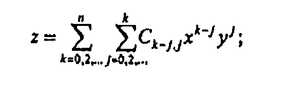
- In particular, a method of designing the ophthalmic lens element described above may include modifying the representation of the front surface to at least partially adjust for observed optical aberrations over the substantially entire aperture of the ophthalmic lens element; the method further including selecting a base surface function in the form of an n'th order symmetric polynomial:

selecting a merit function, M, relating to at least one optical aberration characteristic of the lens element that needs to be minimised;
computing the co-effcients of the symmetric polynomial surface Ck-ij that minimise the merit function over the substantially entire aperture of the ophthalmic lens element;
applying this correction to the front surface;
modifying the addition power component of the front surface to take into account the change in base curve introduced by the correction; and fabricating an ophthalmic lens element having a back surface shaped according to the modified surface function. - The present invention provides a method of designing an ophthalmic lens element such as that described above, the lens element including an upper viewing zone providing good optical quality at a predetermined low surface power over a large area of vision; said predetermined power being determined by the wearer's distance prescription, the horizontal fitting position normally being determined by the interpupillary distance of the wearer, and the vertical fitting position normally being determined by the vertical frame midpoint; a lower viewing zone of higher surface power determined by the wearer's near prescription requirements; and
a corridor of relatively low astigmatism extending therebetween;
the lens element including a front surface and a back surface;
wherein the front surface is achieved by providing a base surface function in the form of a progressive lens surface and by minimising a merit function, M, to reduce optical blur and maximise the width of vision in the upper and lower viewing zones of the lens by using finite element methods to solve the corresponding ophthalmic problem;
and wherein the back surface includes the cylinder prescription requirements of the wearer during the optical optimisation, resulting in a finite element solution of the required lens surface, the back surface cylinder correction being in the form of a toric component to provide an astigmatic correction. - As stated above, the design requirements for any progressive lens surface may differ based on whether the wearer is a myope, emmetrope, hyperope, or other category of patient, or may differ based on the lens base curve, distance prescription, or the level of addition power required by the wearer. Accordingly, the progressive ophthalmic lens element of the present invention may be a member of a series of such elements.
- Such a progressive ophthalmic lens element series may be characterised in that lens elements from different sets having substantially the same addition power, having substantially the same optical field of vision in at least one of the upper and lower viewing zones. The progressive design may be provided on a single surface of the lens element.
- Thus, the present invention also provides a series of progressive ophthalmic lens elements, the series including, for a given base/add combination, a member having a general progressive lens surface for 0.00D cylinder and four or more members having a progressive lens surface corrected for a cylinder prescription, each member of the series corrected for cylinder prescription including:
- a front surface that includes an upper viewing zone having a surface power suitable for distance vision, a lower viewing zone having a surface power suitable for near vision, and a corridor of relatively low astigmatism connecting the upper and lower viewing zones, the corridor being a part of an intermediate viewing zone having a surface power varying from that of the upper viewing zone to that of the lower viewing zone; and
- a back surface;
- wherein the front surface includes at least one correction to improve optical performance of the lens element by compensating for a cylinder correction applied to, or to be applied to, the back surface, the back surface cylinder correction being in the form of a toric component to provide an astigmatic correction, and wherein the front surface includes a general aspheric correction optimised for at least two principal lens meridional directions.
- Preferably, each lens element within a set having an addition power between approximately 0.50 D to 3.50 D has substantially the same optical field of vision in the lower viewing zone for each category of patient.
- In this respect, the applicant has shown that progressive lenses, where the surface has been optimised for a cylinder axis selected from 0°, 45°, 90° or 135°, exhibit substantial optical performance improvements over the entire range of cylinder axes. It has also been observed that a progressive lens surface optimised for a cylinder correction of -2.50 D results in substantial optical performance improvements when utilised for cases where the cylindrical correction ranges from -1.00 D to -4.00 D when compared with those optimised for the exact cylinder values.
- Accordingly, a preferred example of such a product series includes, for a given base/add combination, a general progressive lens surface for 0.00 D cyl to -0.75 D of cylinder correction regardless of axis and four corrected surfaces used for the cylinder range of -1.00 D to -4.00 D, for axes of 0°, 45°, 90° and 135°.
- The progressive ophthalmic lens element may be formed from glass or a polymeric article. The polymeric article, where applicable, may be of any suitable type. A polycarbonate, for example a material of the diallyl glycol carbonate type, may be used. The polymeric article may be formed from cross-linkable polymeric casting compositions, for example as described in United States patent
4,912,155 . Such cross-linkable polymeric casting compositions may include a diacrylate or dimethacrylate monomer (such as polyoxyalkylene glycol diacrylate or dimethacrylate or a bisphenol fluorene diacrylate or dimethacrylate) and a polymerisable comonomer, e.g. methacrylates, acrylates, vinyls, vinyl ethers, allyls, aromatic olefins, ethers, polythiols and the like. - The present invention will now be more fully described with reference to the accompanying examples. However, it should be understood that the following description is illustrative only and should not be taken in any way as a restriction on the generality of the invention described above.
-
Figures 1 and2 compare a conventional progressive lens and the progressive lens corrected according to the present invention for the -2.50 D cylinder prescription at two cylinder axis orientations, namely 180° and 90° respectively. -
Figure 3 shows a comparison of optical RMS blur contour plots of a conventional progressive lens and a progressive lens optimised for the -2.50 D at 180° of cylinder. In particular,Figures 3 (a) and 3 (c) show the conventional progressive with values of prescription -2.00 D and -3.00 D of cylinder respectively.Figures 3 (b) and 3(d) show the progressive lens in accordance with the present invention for the same prescription values where the front surface is the surface which has been optimised for the -2.50 D at 180° of cylinder. All of the Figures contain contour levels of 0.5 D, 1.0 D, 1.5 D, 2.0 D, 2.5 D etc. - Describing the Figures in more detail,
Figures 1 to 3 demonstrate two examples of the present invention. Each of the Figures contains 2 x 2 frames. The first column illustrates a conventional progressive lens with a rotationally symmetric base curve. The second column (Figure 1 (b), 1(d) ,2 (b) and 2 (d) ) shows a progressive lens in accordance with the present invention with a general aspheric base surface. - It should be noted that the Optical RMS Blur plots consider an object field that varies throughout the lens from infinity for the upper distance viewing zone region to approximately 40 cm in the lower, near viewing zone. In addition, for the calculation of RMS blur it was assumed the wearer could accommodate up to 0.50 D of power error for eye elevations below 10°. The distance between the centre of rotation of the eye and the lens back vertex was set to 27 mm and the lens material index was 1.537.
- It should be further noted that the optimised surface of Column 2 may be achieved either by applying the correction surface or by direct calculation, utilising optical optimisation methods.
-
Figures 1 and2 illustrate lenses of mean through power +4.25 D. In particular,Figure 1 illustrates a lens with a base curve of 6.85 D and an addition power of 2.00 D.Figure 1 (a) illustrates the surface astigmatism of the conventional progressive, whileFigure 1 (b) illustrates the surface astigmatism of the progressive surface corrected for the prescription requirements of +5.50 D and a cylinder axis of -2.50 D at 180°.Figure 1 (c) and Figure 1 (d) illustrate the RMS Blur that results with the conventional and corrected surfaces respectively for the prescription of +5.50 D and -2.50 D cylinder at 180°. -
Figure 2 illustrates a lens with a base curve of 6.85 D and an addition power of 2.00 D.Figure 2 (a) illustrates the surface astigmatism of the conventional progressive, whileFigure 2 (b) illustrates the surface astigmatism of the progressive surface corrected for the prescription requirements of +5.50 D and a cylinder axis of -2.50 D at 90°.Figure 2 (c) and Figure 2 (d) illustrate the RMS Blur that results with the conventional and corrected surfaces respectively for the prescription of +5.50 D and -2.50 D cylinder at 90°. - The differences in the RMS blur contour demonstrate a significant improvement in the optical performance of the corrected lens. This is indicated by the reduction in RMS blur of
Figure 1(d) to that ofFigure 1 (c) , and likewise when comparingFigure 2 (d) and Figure 2 (c) . -
Figure 3 illustrates the gains in optical performance for two cylinder prescriptions deviating from the optimised one. - It can be seen from these results that the surface corrected for -2.50 D of cylinder results in substantially improved performance for the examples given, when compared with the conventional progressive, and similar performance to the fully optimised example of
Figure 1 (d) .
Claims (10)
- A method of designing an ophthalmic lens element, said lens element including:an upper viewing zone providing good optical quality at a predetermined low surface power over a large area of vision; said predetermined power being determined by the wearer's distance prescription, the horizontal fitting position normally being determined by the interpupillary distance of the wearer, and the vertical fitting position normally being determined by the vertical frame midpoint; a lower viewing zone of higher surface power determined by the wearer's near prescription requirements; anda corridor of relatively low astigmatism extending therebetween;the lens element including a front surface and a back surface;wherein the front surface is achieved by providing a base surface function in the form of a progressive lens surface and by minimising a merit function, M, to reduce optical blur and maximise the width of vision in the upper and lower viewing zones of the lens by using finite element methods to solve the corresponding ophthalmic problem;and wherein the back surface includes the cylinder prescription requirements of the wearer during the optical optimisation, resulting in a finite element solution of the required lens surface, the back surface cylinder correction being in the form of a toric component to provide an astigmatic correction.
- A series of progressive ophthalmic lens elements, the series including, for a given base/add combination, a member having a general progressive lens surface for 0.00D cylinder and four or more members having a progressive lens surface corrected for a cylinder prescription, each member of the series corrected for cylinder prescription including:a front surface that includes an upper viewing zone having a surface power suitable for distance vision, a lower viewing zone having a surface power suitable for near vision, anda corridor of relatively low astigmatism connecting the upper and lower viewing zones, the corridor being a part of an intermediate viewing zone having a surface power varying from that of the upper viewing zone to that of the lower viewing zone; anda back surface;wherein the front surface includes at least one correction to improve optical performance of the lens element by compensating for a cylinder correction applied to, or to be applied to, the back surface, the back surface cylinder correction being in the form of a toric component to provide an astigmatic correction, and wherein the front surface includes a general aspheric correction optimised for at least two principal lens meridional directions.
- A series of progressive lens elements according to claim 2, wherein the front surface correction varies depending on the axis of the cylinder correction of the back surface.
- A series of progressive lens elements according to claim 2 or claim 3, wherein the front surface correction varies depending on the distance Rx power, or covers a range of distance Rx powers.
- A series of progressive lens elements according to any one of claims 2 to 4 exhibiting differing cylinder corrections in at least the upper and lower viewing zones of the front surface, wherein the front surface correction varies depending on the addition power.
- A series of progressive lens elements according to any one of claims 2 to 5, wherein the front surface correction has been achieved by replacing a rotationally symmetric base curve with a general aspheric surface of the form of an n'th order symmetric polynomial:
- A series of progressive lens elements according to any one of claims 2 to 5, wherein the front surface correction has been achieved by a method of optical optimisation where a suitably constructed merit function relating to the optical performance of the lens in the as worn eye-lens configuration is optimised for one or more of distance, intermediate, or near zone vision, depending on the Rx needs of the wearer.
- A series of progressive lens elements according to any one of claims 2 to 5, wherein the front surface correction is achieved by consideration of a merit function including an optimisation function to minimise optical blur where the optimisation function seeks to minimise a blur measure, M.
- A series of progressive lens elements according to any one of claims 2 to 8, wherein each lens element within a series having an addition power between about 0.50 D to 3.50 D has substantially the same optical field of vision in the lower viewing zone for each category of patient.
- A series of progressive lens elements according to any one of claims 2 to 9, including for a given base/add combination, a general progressive lens surface for 0.00 D cyl to -0.75 D of cylinder correction regardless of axis, and four corrected surfaces used for the cylinder range of -1.00 D to -4.00 D, for axes of 0°, 45°, 90° and 135°.
Applications Claiming Priority (3)
| Application Number | Priority Date | Filing Date | Title |
|---|---|---|---|
| AUPO903197 | 1997-09-09 | ||
| AUPO9031A AUPO903197A0 (en) | 1997-09-09 | 1997-09-09 | Improved progressive lens |
| PCT/AU1998/000733 WO1999013374A1 (en) | 1997-09-09 | 1998-09-09 | Improved progressive lens |
Publications (3)
| Publication Number | Publication Date |
|---|---|
| EP1019779A1 EP1019779A1 (en) | 2000-07-19 |
| EP1019779A4 EP1019779A4 (en) | 2000-11-02 |
| EP1019779B1 true EP1019779B1 (en) | 2012-10-03 |
Family
ID=3803316
Family Applications (1)
| Application Number | Title | Priority Date | Filing Date |
|---|---|---|---|
| EP98941160A Expired - Lifetime EP1019779B1 (en) | 1997-09-09 | 1998-09-09 | Improved progressive lens |
Country Status (4)
| Country | Link |
|---|---|
| US (1) | US6260967B1 (en) |
| EP (1) | EP1019779B1 (en) |
| AU (1) | AUPO903197A0 (en) |
| WO (1) | WO1999013374A1 (en) |
Families Citing this family (21)
| Publication number | Priority date | Publication date | Assignee | Title |
|---|---|---|---|---|
| US6366823B1 (en) * | 1998-07-30 | 2002-04-02 | Asahi Kogaku Kogyo Kabushiki Kaisha | Design method for optical curved surface |
| FR2783938B1 (en) † | 1998-09-28 | 2000-11-17 | Essilor Int | TORIC OPHTHALMIC LENSES |
| IL132466A (en) * | 1999-05-20 | 2002-09-12 | Johnson & Johnson Vision Care | Methods for producing progressive addition lenses |
| AUPQ065599A0 (en) | 1999-05-31 | 1999-06-24 | Sola International Holdings Ltd | Progressive lens |
| AU771955B2 (en) * | 1999-05-31 | 2004-04-08 | Carl Zeiss Vision Australia Holdings Ltd | Progressive lens |
| US6343860B1 (en) * | 1999-08-26 | 2002-02-05 | Greenhouse Grown Products, Inc. | Toric-shaped lenses and goggle assembly |
| CA2386062A1 (en) * | 1999-10-01 | 2001-04-12 | Sola International Holdings Ltd. | Progressive lens |
| US6778724B2 (en) * | 2000-11-28 | 2004-08-17 | The Regents Of The University Of California | Optical switching and sorting of biological samples and microparticles transported in a micro-fluidic device, including integrated bio-chip devices |
| EP1461662B1 (en) * | 2001-12-05 | 2014-05-14 | Carl Zeiss Vision Australia Holdings Ltd. | Balanced progressive lens |
| FR2884325B1 (en) * | 2005-04-08 | 2007-06-01 | Essilor Int | OPHTHALMIC LENS |
| FR2888344B1 (en) * | 2005-07-11 | 2007-09-14 | Essilor Int | OPHTHALMIC LENS |
| FR2893151B1 (en) * | 2005-11-08 | 2008-02-08 | Essilor Int | OPHTHALMIC LENS. |
| FR2894038B1 (en) * | 2005-11-29 | 2008-03-07 | Essilor Int | OPHTHALMIC LENS. |
| FR2895092B1 (en) | 2005-12-16 | 2008-02-29 | Essilor Int | METHOD FOR DETERMINING AN OPHTHALMIC LENS |
| US20080189838A1 (en) * | 2007-02-12 | 2008-08-14 | Mage Jerome J M | Multi-base lens goggle |
| FR2944364B1 (en) | 2009-04-14 | 2011-09-02 | Essilor Int | PERFORMING A PERSONALIZED GLASS GLASS BASED ON A PERCEPTION OF FLOU |
| US10330950B2 (en) | 2017-02-23 | 2019-06-25 | Indizen Optical Technologies of America, LLC | Progressive lenses with reduced peripheral mean sphere |
| US20190064543A1 (en) * | 2017-08-30 | 2019-02-28 | Johnson & Johnson Vision Care, Inc. | Atoric Surfaces to Minimize Secondary Astigmatism in Contact Lenses for the Correction of Astigmatism |
| EP3859433A4 (en) * | 2018-09-28 | 2022-08-24 | Hoya Lens Thailand Ltd. | System for designing progressive refractive power lens, method for designing progressive refractive power lens, and progressive refractive power lens group |
| EP3663838A1 (en) * | 2018-12-03 | 2020-06-10 | Carl Zeiss Vision International GmbH | Spectacle lens, family of spectacle lenses, method for designing a spectacle lens family and method for producing a spectacle lens |
| US11520308B2 (en) | 2020-07-29 | 2022-12-06 | Indizen Optical Technologies of America, LLC | Progressive lenses with variable reduced peripheral mean sphere |
Citations (1)
| Publication number | Priority date | Publication date | Assignee | Title |
|---|---|---|---|---|
| DE1145820B (en) * | 1956-10-06 | 1963-03-21 | Saint Gobain | Lens |
Family Cites Families (6)
| Publication number | Priority date | Publication date | Assignee | Title |
|---|---|---|---|---|
| US5771089A (en) | 1984-08-17 | 1998-06-23 | Optische Werke G. Rodenstock | Progressive spectacle lens |
| US4838675A (en) * | 1987-06-19 | 1989-06-13 | Sola International Holdings, Ltd. | Method for improving progressive lens designs and resulting article |
| US4969729A (en) | 1988-08-19 | 1990-11-13 | 501 Opticast International Corporation | Composite plastic lens having a positioned optical axis and method of making the same |
| DE4210008A1 (en) | 1992-03-27 | 1993-09-30 | Zeiss Carl Fa | Eyeglass lens |
| IL117937A0 (en) | 1995-05-04 | 1996-08-04 | Johnson & Johnson Vision Prod | Combined multifocal toric lens designs |
| US6149271A (en) * | 1998-10-23 | 2000-11-21 | Innotech, Inc. | Progressive addition lenses |
-
1997
- 1997-09-09 AU AUPO9031A patent/AUPO903197A0/en not_active Abandoned
-
1998
- 1998-09-09 EP EP98941160A patent/EP1019779B1/en not_active Expired - Lifetime
- 1998-09-09 WO PCT/AU1998/000733 patent/WO1999013374A1/en active Application Filing
- 1998-09-09 US US09/486,978 patent/US6260967B1/en not_active Expired - Lifetime
Patent Citations (1)
| Publication number | Priority date | Publication date | Assignee | Title |
|---|---|---|---|---|
| DE1145820B (en) * | 1956-10-06 | 1963-03-21 | Saint Gobain | Lens |
Also Published As
| Publication number | Publication date |
|---|---|
| EP1019779A1 (en) | 2000-07-19 |
| EP1019779A4 (en) | 2000-11-02 |
| WO1999013374A1 (en) | 1999-03-18 |
| AUPO903197A0 (en) | 1997-10-02 |
| US6260967B1 (en) | 2001-07-17 |
Similar Documents
| Publication | Publication Date | Title |
|---|---|---|
| EP1019779B1 (en) | Improved progressive lens | |
| EP1188091B1 (en) | Progressive lens | |
| US7159983B2 (en) | Multifocal lenses for pre-presbyopic individuals | |
| EP0809127B9 (en) | Multifocal lens for eyeglasses and eyeglass lens | |
| EP1029254B1 (en) | Improved ophthalmic lens | |
| EP0891574B1 (en) | Progressive lens elements and methods for designing and using same | |
| US6709105B2 (en) | Progressive addition lenses | |
| US6851803B2 (en) | Ophthalmic lenses with reduced chromatic blur | |
| EP0809126A1 (en) | Gradient index multifocal lens, spectacle lens, and manufacture of gradient index multifocal lens | |
| CA2614910C (en) | Ophthalmic lens | |
| US8042940B2 (en) | Opthalmic lenses having reduced base out prism | |
| EP1214623B1 (en) | Progressive addition lenses | |
| EP1882973A1 (en) | Design method for spectacle lens, spectacle lens, and spectacles | |
| AU2002252366A1 (en) | Progressive addition lenses | |
| EP2780758B1 (en) | A method for determining an ophthalmic lens | |
| US9360684B2 (en) | Method for determining target optical functions | |
| US6505930B1 (en) | Spectacles frames for shaped lens elements | |
| EP3526641B1 (en) | Reduced distortion spectacle lens | |
| JPH0239769B2 (en) | RUISHINTASHOTENRENZU | |
| AU4735400A (en) | Progressive lens |
Legal Events
| Date | Code | Title | Description |
|---|---|---|---|
| PUAI | Public reference made under article 153(3) epc to a published international application that has entered the european phase |
Free format text: ORIGINAL CODE: 0009012 |
|
| 17P | Request for examination filed |
Effective date: 20000218 |
|
| AK | Designated contracting states |
Kind code of ref document: A1 Designated state(s): AT BE CH CY DE DK ES FI FR GB GR IE IT LI LU MC NL PT SE |
|
| A4 | Supplementary search report drawn up and despatched |
Effective date: 20000918 |
|
| AK | Designated contracting states |
Kind code of ref document: A4 Designated state(s): AT BE CH CY DE DK ES FI FR GB GR IE IT LI LU MC NL PT SE |
|
| RIC1 | Information provided on ipc code assigned before grant |
Free format text: 7G 02C 7/06 A, 7G 02C 7/02 B |
|
| 17Q | First examination report despatched |
Effective date: 20060711 |
|
| RAP1 | Party data changed (applicant data changed or rights of an application transferred) |
Owner name: CARL ZEISS VISION AUSTRALIA HOLDINGS LTD. |
|
| GRAP | Despatch of communication of intention to grant a patent |
Free format text: ORIGINAL CODE: EPIDOSNIGR1 |
|
| GRAS | Grant fee paid |
Free format text: ORIGINAL CODE: EPIDOSNIGR3 |
|
| GRAA | (expected) grant |
Free format text: ORIGINAL CODE: 0009210 |
|
| AK | Designated contracting states |
Kind code of ref document: B1 Designated state(s): AT BE CH CY DE DK ES FI FR GB GR IE IT LI LU MC NL PT SE |
|
| REG | Reference to a national code |
Ref country code: GB Ref legal event code: FG4D |
|
| REG | Reference to a national code |
Ref country code: AT Ref legal event code: REF Ref document number: 578226 Country of ref document: AT Kind code of ref document: T Effective date: 20121015 Ref country code: CH Ref legal event code: EP |
|
| REG | Reference to a national code |
Ref country code: IE Ref legal event code: FG4D |
|
| REG | Reference to a national code |
Ref country code: DE Ref legal event code: R096 Ref document number: 69842860 Country of ref document: DE Effective date: 20121129 |
|
| REG | Reference to a national code |
Ref country code: AT Ref legal event code: MK05 Ref document number: 578226 Country of ref document: AT Kind code of ref document: T Effective date: 20121003 |
|
| REG | Reference to a national code |
Ref country code: NL Ref legal event code: VDEP Effective date: 20121003 |
|
| PG25 | Lapsed in a contracting state [announced via postgrant information from national office to epo] |
Ref country code: FI Free format text: LAPSE BECAUSE OF FAILURE TO SUBMIT A TRANSLATION OF THE DESCRIPTION OR TO PAY THE FEE WITHIN THE PRESCRIBED TIME-LIMIT Effective date: 20121003 Ref country code: SE Free format text: LAPSE BECAUSE OF FAILURE TO SUBMIT A TRANSLATION OF THE DESCRIPTION OR TO PAY THE FEE WITHIN THE PRESCRIBED TIME-LIMIT Effective date: 20121003 Ref country code: NL Free format text: LAPSE BECAUSE OF FAILURE TO SUBMIT A TRANSLATION OF THE DESCRIPTION OR TO PAY THE FEE WITHIN THE PRESCRIBED TIME-LIMIT Effective date: 20121003 |
|
| PG25 | Lapsed in a contracting state [announced via postgrant information from national office to epo] |
Ref country code: CY Free format text: LAPSE BECAUSE OF FAILURE TO SUBMIT A TRANSLATION OF THE DESCRIPTION OR TO PAY THE FEE WITHIN THE PRESCRIBED TIME-LIMIT Effective date: 20121003 Ref country code: PT Free format text: LAPSE BECAUSE OF FAILURE TO SUBMIT A TRANSLATION OF THE DESCRIPTION OR TO PAY THE FEE WITHIN THE PRESCRIBED TIME-LIMIT Effective date: 20130204 Ref country code: GR Free format text: LAPSE BECAUSE OF FAILURE TO SUBMIT A TRANSLATION OF THE DESCRIPTION OR TO PAY THE FEE WITHIN THE PRESCRIBED TIME-LIMIT Effective date: 20130104 Ref country code: BE Free format text: LAPSE BECAUSE OF FAILURE TO SUBMIT A TRANSLATION OF THE DESCRIPTION OR TO PAY THE FEE WITHIN THE PRESCRIBED TIME-LIMIT Effective date: 20121003 |
|
| PG25 | Lapsed in a contracting state [announced via postgrant information from national office to epo] |
Ref country code: AT Free format text: LAPSE BECAUSE OF FAILURE TO SUBMIT A TRANSLATION OF THE DESCRIPTION OR TO PAY THE FEE WITHIN THE PRESCRIBED TIME-LIMIT Effective date: 20121003 |
|
| PG25 | Lapsed in a contracting state [announced via postgrant information from national office to epo] |
Ref country code: DK Free format text: LAPSE BECAUSE OF FAILURE TO SUBMIT A TRANSLATION OF THE DESCRIPTION OR TO PAY THE FEE WITHIN THE PRESCRIBED TIME-LIMIT Effective date: 20121003 |
|
| PLBE | No opposition filed within time limit |
Free format text: ORIGINAL CODE: 0009261 |
|
| STAA | Information on the status of an ep patent application or granted ep patent |
Free format text: STATUS: NO OPPOSITION FILED WITHIN TIME LIMIT |
|
| 26N | No opposition filed |
Effective date: 20130704 |
|
| REG | Reference to a national code |
Ref country code: DE Ref legal event code: R097 Ref document number: 69842860 Country of ref document: DE Effective date: 20130704 |
|
| PG25 | Lapsed in a contracting state [announced via postgrant information from national office to epo] |
Ref country code: MC Free format text: LAPSE BECAUSE OF FAILURE TO SUBMIT A TRANSLATION OF THE DESCRIPTION OR TO PAY THE FEE WITHIN THE PRESCRIBED TIME-LIMIT Effective date: 20121003 |
|
| REG | Reference to a national code |
Ref country code: CH Ref legal event code: PL |
|
| REG | Reference to a national code |
Ref country code: IE Ref legal event code: MM4A |
|
| PG25 | Lapsed in a contracting state [announced via postgrant information from national office to epo] |
Ref country code: IE Free format text: LAPSE BECAUSE OF NON-PAYMENT OF DUE FEES Effective date: 20130909 Ref country code: LI Free format text: LAPSE BECAUSE OF NON-PAYMENT OF DUE FEES Effective date: 20130930 Ref country code: CH Free format text: LAPSE BECAUSE OF NON-PAYMENT OF DUE FEES Effective date: 20130930 |
|
| PG25 | Lapsed in a contracting state [announced via postgrant information from national office to epo] |
Ref country code: ES Free format text: LAPSE BECAUSE OF FAILURE TO SUBMIT A TRANSLATION OF THE DESCRIPTION OR TO PAY THE FEE WITHIN THE PRESCRIBED TIME-LIMIT Effective date: 20121003 |
|
| PG25 | Lapsed in a contracting state [announced via postgrant information from national office to epo] |
Ref country code: LU Free format text: LAPSE BECAUSE OF NON-PAYMENT OF DUE FEES Effective date: 20130909 |
|
| REG | Reference to a national code |
Ref country code: FR Ref legal event code: PLFP Year of fee payment: 19 |
|
| REG | Reference to a national code |
Ref country code: FR Ref legal event code: PLFP Year of fee payment: 20 |
|
| PGFP | Annual fee paid to national office [announced via postgrant information from national office to epo] |
Ref country code: FR Payment date: 20170928 Year of fee payment: 20 Ref country code: IT Payment date: 20170926 Year of fee payment: 20 Ref country code: GB Payment date: 20170921 Year of fee payment: 20 Ref country code: DE Payment date: 20170928 Year of fee payment: 20 |
|
| REG | Reference to a national code |
Ref country code: DE Ref legal event code: R071 Ref document number: 69842860 Country of ref document: DE |
|
| REG | Reference to a national code |
Ref country code: GB Ref legal event code: PE20 Expiry date: 20180908 |
|
| PG25 | Lapsed in a contracting state [announced via postgrant information from national office to epo] |
Ref country code: GB Free format text: LAPSE BECAUSE OF EXPIRATION OF PROTECTION Effective date: 20180908 |