EP1019693B1 - Template for designing human seating accomodations - Google Patents
Template for designing human seating accomodations Download PDFInfo
- Publication number
- EP1019693B1 EP1019693B1 EP98940883A EP98940883A EP1019693B1 EP 1019693 B1 EP1019693 B1 EP 1019693B1 EP 98940883 A EP98940883 A EP 98940883A EP 98940883 A EP98940883 A EP 98940883A EP 1019693 B1 EP1019693 B1 EP 1019693B1
- Authority
- EP
- European Patent Office
- Prior art keywords
- section
- seat
- torso
- percentile
- posture
- Prior art date
- Legal status (The legal status is an assumption and is not a legal conclusion. Google has not performed a legal analysis and makes no representation as to the accuracy of the status listed.)
- Expired - Lifetime
Links
- 238000013461 design Methods 0.000 claims description 150
- 210000000689 upper leg Anatomy 0.000 claims description 59
- 230000007935 neutral effect Effects 0.000 claims description 34
- 244000309466 calf Species 0.000 claims description 30
- 210000004197 pelvis Anatomy 0.000 claims description 25
- 210000004394 hip joint Anatomy 0.000 claims description 20
- 210000003423 ankle Anatomy 0.000 claims description 18
- 210000003127 knee Anatomy 0.000 claims description 18
- 210000002683 foot Anatomy 0.000 claims description 11
- 210000001624 hip Anatomy 0.000 claims description 11
- 239000000463 material Substances 0.000 claims description 11
- 210000000544 articulatio talocruralis Anatomy 0.000 claims description 10
- 210000000629 knee joint Anatomy 0.000 claims description 10
- 210000000323 shoulder joint Anatomy 0.000 claims description 9
- 230000008859 change Effects 0.000 claims description 5
- 210000000988 bone and bone Anatomy 0.000 claims description 2
- 210000003205 muscle Anatomy 0.000 claims description 2
- 210000004061 pubic symphysis Anatomy 0.000 claims description 2
- 210000001562 sternum Anatomy 0.000 claims description 2
- 230000036544 posture Effects 0.000 description 135
- 238000000034 method Methods 0.000 description 59
- 210000002414 leg Anatomy 0.000 description 19
- 210000000038 chest Anatomy 0.000 description 13
- 239000000725 suspension Substances 0.000 description 13
- 210000002239 ischium bone Anatomy 0.000 description 10
- 230000004308 accommodation Effects 0.000 description 9
- 230000008901 benefit Effects 0.000 description 9
- 238000006073 displacement reaction Methods 0.000 description 9
- 210000001503 joint Anatomy 0.000 description 6
- 230000033001 locomotion Effects 0.000 description 6
- 210000004705 lumbosacral region Anatomy 0.000 description 6
- 230000004438 eyesight Effects 0.000 description 4
- 239000002184 metal Substances 0.000 description 4
- 238000004806 packaging method and process Methods 0.000 description 4
- 239000002023 wood Substances 0.000 description 4
- 230000004888 barrier function Effects 0.000 description 3
- 230000007423 decrease Effects 0.000 description 3
- 238000005259 measurement Methods 0.000 description 3
- 210000000115 thoracic cavity Anatomy 0.000 description 3
- 241000501754 Astronotus ocellatus Species 0.000 description 2
- 210000003484 anatomy Anatomy 0.000 description 2
- 230000037396 body weight Effects 0.000 description 2
- 238000012938 design process Methods 0.000 description 2
- 239000004744 fabric Substances 0.000 description 2
- 239000006260 foam Substances 0.000 description 2
- 230000005484 gravity Effects 0.000 description 2
- 239000010985 leather Substances 0.000 description 2
- 230000033228 biological regulation Effects 0.000 description 1
- 230000001419 dependent effect Effects 0.000 description 1
- 238000011161 development Methods 0.000 description 1
- 230000000694 effects Effects 0.000 description 1
- 210000003414 extremity Anatomy 0.000 description 1
- 238000011835 investigation Methods 0.000 description 1
- 238000004519 manufacturing process Methods 0.000 description 1
- 230000007246 mechanism Effects 0.000 description 1
- 238000012986 modification Methods 0.000 description 1
- 230000004048 modification Effects 0.000 description 1
- 230000035515 penetration Effects 0.000 description 1
- 230000005180 public health Effects 0.000 description 1
- 230000000452 restraining effect Effects 0.000 description 1
- 210000001519 tissue Anatomy 0.000 description 1
Images




Classifications
-
- A—HUMAN NECESSITIES
- A47—FURNITURE; DOMESTIC ARTICLES OR APPLIANCES; COFFEE MILLS; SPICE MILLS; SUCTION CLEANERS IN GENERAL
- A47C—CHAIRS; SOFAS; BEDS
- A47C31/00—Details or accessories for chairs, beds, or the like, not provided for in other groups of this subclass, e.g. upholstery fasteners, mattress protectors, stretching devices for mattress nets
- A47C31/12—Means, e.g. measuring means, for adapting chairs, beds or mattresses to the shape or weight of persons
- A47C31/126—Means, e.g. measuring means, for adapting chairs, beds or mattresses to the shape or weight of persons for chairs
Definitions
- the present invention relates generally to two-dimensional templates and, more particularly, to a two-dimensional design template used for designing, evaluating and measuring human occupant accommodation and seating in a seated environment.
- Automotive vehicle seats have three primary functions: (1) position occupant for the driving task; (2) support comfortable healthy sitting postures; and (3) protect occupant upon vehicle impact.
- a deformable pad on a mechanically adjustable seat frame accomplishes the first function and the second function is accomplished through the geometrical and mechanical properties of the deformable pad composed of padding, suspension and upholstery.
- the third function is accomplished by seat and restraint systems to restrain the occupant during a vehicle impact.
- the first two functions determine the greatest portion of the occupant's perceived level of comfort.
- Position has been considered a primary determinant of occupant comfort and posture has been relegated to the occupant's ability to adapt to the vehicle environment.
- a major function of seat position and its supporting surfaces is, however, to support the occupant's posture.
- the point of greatest deflection in the deformable pad or seat cushion is defined on the thigh segment which means that the location of this point is dependent upon thigh angle.
- the greatest deflection in the seat cushion is under the pelvis and is defined by the position and posture of the torso.
- Another disadvantage with the above tool for use as a seat design tool is the posture of the torso in the above tool is undefined. Since the above tool was built from measurements of men sitting in a bench seat, it is reasonable to assume that the posture is slouched. Current seats are built with the intent of supporting a healthy erect posture in the back. The above tool does not provide any information regarding the location of the anatomical structures that define this posture.
- the contour of the interface between occupant and seat does not have contours that represent the deformed centerline contour of the occupant/seat interface.
- US5483825 discloses an apparatus for measuring the performance of an accelerator pedal of a motor vehicle comprising a torso portion connected via a hip portion to a leg.
- the leg has a knee joint and an ankle joint connecting the leg to a foot.
- Various transducers and angular scales are located on the respective joints to measure certain performance characteristics of the accelerator pedal such as force for operating the pedal and foot angle whilst operating the pedal.
- US5456019 discloses a method and apparatus for locating the coordinates of a vehicle seat hip pivot axis, or H-point.
- the apparatus comprises a measuring device slidably mounted on a base assembly, the measuring device having a telescopic pointer for determining the H-point.
- a vehicle seat is supported on the base assembly, and a weighted manikin having an H-point indicator is placed in the seat. The measuring device is then used to determine the H-point for that seat.
- US4669302 discloses an apparatus for measuring the shape and contour of a mattress under a load.
- the apparatus comprises a humanoid dummy having moveable joints. Sensors are located on the joints such that when the dummy is placed on a mattress, deflection occurs at the joints and the sensors provide an indication of the shape or contour of the mattress by correlation of the relative movement that occurs at the joints.
- a design template is provided to design, evaluate and measure vehicle occupant accommodation.
- a design template is provided to represent the occupant that incorporates posture as part of their geometric representation of the occupant.
- the design template correctly represents the anatomy, biomechanics, and anthropometry of typical human occupants and is simple to use.
- the design template accurately defines the contact contours between the occupant and seat.
- a seat can be designed with the design template to provide support and comfort to a human body occupant.
- the design template can be used to design an occupant restraint system for a seat.
- the design template can be used to establish occupant accommodation criteria in a vehicle package based on a predetermined class of vehicles.
- a design template 10 is illustrated in operational relationship with a seat, generally indicated at 12, of an automotive vehicle (not shown).
- the automotive vehicle includes a floor pan 14 which includes a toe pan or toe board 16 adjacent to a front end thereof.
- the seat 12 is mounted on the floor pan 14 by suitable adjustable mounting mechanisms (not shown).
- the seat 12 includes a seat cushion 18 to primarily support a torso weight under an ischium of a human body occupant and a weight of a thigh of the human body occupant and a seat back 20 to support a back of the human body occupant primarily in a thoracic and lumbar regions of the human body occupant. It should be appreciated that the design of the seat cushion 18 and seat back 20 will be in accordance with the design template 10 to resiliently and comfortably support the human body occupant when seated thereon.
- the design template 10 is used to design the seat 12.
- the design template 10 includes at least one torso section 22.
- the torso sections 22 are dimensionally accurate to simulate or represent body size of a human male who is 95 th percentile in weight and stature, a human male who is 50 th percentile in weight and stature or a human female who is 5 th percentile in weight and stature. It should be appreciated that the 5 th percentile female represents the smallest body size while the 95 th percentile male represents the largest body size.
- the development of the design template 10 has relied upon the U.S. Public Health Service for height and weight description of the general population and the U.S. military for the anthropometric dimensions of the human body that are used in ergonomic design.
- Anthropometric surveys measure people in standardized sitting and standing postures. Since the purpose of the design template 10 is to represent the human body in anatomically and biomechanically correct sitting postures, additional data had to be collected that would describe the sitting posture of the human body.
- Sitting posture is primarily a function of torso posture. As a result, an investigation was conducted of torso back shape in different sitting postures.
- the results can be divided into two parts: 1) the size and shape of the torso sections 22 and 2) the size and shape of the leg sections (thigh sections 44, calf sections 52 and shoe sections 62 to be described).
- the human body was divided into three sizes: small female, average male and large male.
- the torso was divided into three shapes representing three postures: ERECT, NEUTRAL and SLUMPED.
- the human body sizes were defined by anthropometric dimensions and regression equations that describe the relationships between the dimensions.
- the torso shapes were mathematically defined from measurements of subjects in five positions.
- Subjects were used to define the three postures if they had back curvatures within mathematically prescribed limits that define ERECT (lumbar extension with a relative curvature greater than 0.6 radians per spine height), NEUTRAL (straight lumbar spine with a relative curvature between +0.6 and -0.6 radians per spine height) and SLUMPED (lumbar flexion with a relative curvature less than -0.6 radians per spine height).
- ERECT lumbar extension with a relative curvature greater than 0.6 radians per spine height
- NEUTRAL straight lumbar spine with a relative curvature between +0.6 and -0.6 radians per spine height
- SLUMPED lumbar flexion with a relative curvature less than -0.6 radians per spine height
- the pelvis in both males and females is based upon the average pelvis from an FAA pelvic study by Reynolds in 1982.
- the 95 th percentile male pelvis is scaled up from the average male pelvis and the 5 th percentile female pelvis is scaled down from the average female pelvis.
- the position of the pelvis was measured in each posture described above.
- the three-dimensional coordinates that describe the average pelvis in the FAA skeletal data base are rotated to the same pelvic orientation as the pelvis position in the measured subjects.
- the size of the pelvis was scaled to equal the pelvis size of the subjects in the NEUTRAL posture as represented by the distance between the Ischial Tuberosity and S1.
- the resulting skeletal data are optimally matched for position and size in the measured laboratory subjects.
- the spine was attached at S1 after correcting for tissue thickness in the pelvis and back.
- leg sections were defined for each of the three human body sizes: large male, average male and small female.
- the definition came from anthropometric estimates of the distance between joint centers at the hip, knee and ankle, otherwise referred to as link lengths.
- the depth of the sections was estimated from anthropometric equations that defined the relationship between human body weight and human body depth. These dimensions were used to assemble the thigh and calf sections to look like human segments for each of the three human body sizes.
- the foot is assumed to be covered by an average shoe size for each of the respective human body sizes.
- the small female shoe is a size six, the average and large male shoe sizes are ten and twelve, respectively.
- the location of the ankle joint relative to the shoe was estimated from measurements of live people. It should be appreciated that the above was used to generate the design template 10.
- the torso section 22 is for a 50 th percentile male with a NEUTRAL posture.
- FIG. 2 illustrates a torso section 22 for a 50 th percentile male with an ERECT posture.
- FIG. 3 illustrates a torso section 22 for a 50 th percentile male with a SLUMPED posture.
- the torso section 22 can be for either the 95 th percentile male or 5 th percentile female with either one of a NEUTRAL, ERECT or SLUMPED posture. It is recommended that the seat design process begin with the NEUTRAL posture and proceed to accommodating the ERECT posture while the SLUMPED posture should be supported in every seat, but not encouraged.
- the torso section 22 has an outer contour 23.
- the outer contour 23 has an interface portion 23a conforming to a deformed shape between the seat 12 and a seated human body occupant.
- the outer contour 23 also has an anterior portion 23b that is anthropometrically and anatomically correct.
- the torso section 22 is made of any suitable media to represent the torso of a human body occupant.
- the media may be electronic, paper, wood, plastic or the like.
- the torso section 22 is a sheet of rigid material such as plastic.
- the torso section 22 is preferably transparent.
- the torso section 22 includes anatomical details located relative to each other and the interface contour 23a is located relative to the anatomical details.
- the torso section 22 contains indicia of skeletal landmarks relative to a seated human body occupant.
- the torso section 22 includes a shoulder joint 24 and a hip joint 26 and a line axis 28 connected therebetween.
- the torso section 22 includes a centerline projection of a pelvis with indicia representing an ischial tuberosity, anterior superior iliac spine, pelvic symphysis and sacrum.
- the torso section 22 also has a point I D ° 30 (FIG.
- the torso section 22 also has spinal landmarks 34 marked along the entire length of the back thereof.
- the spinal landmarks 34 are important for correctly placing the lumbar support and for adequate design of the chest support for the seat 12.
- the spinal landmarks 34 are for the neck (cervical spine) indicating C7 at 34a, chest (thoracic spine) indicating T2, T4, T6, T8, T10, T12 at 34b, 34c, 34d, 34e, 34f and 34g, respectively, referred to as point S (FIG.
- hip joint 26 is referred to as the H-point in SAE seat design practice.
- the hip joint is a ball-and-socket joint connecting the thigh to the pelvis of a human body occupant.
- anterior shape of the torso section 22 is anthropometrically and anatomically correct. It should further be appreciated that the location of the hip joint changes with posture.
- the torso section 22 has indicia for the most anterior portion on the top of a pelvis of a human body occupant which is the anterior superior iliac spine (ASIS), point A 36 and a pubic symphysis, point P 38.
- a lap belt to be described should cross below point A 36 and above point P 38.
- the torso section 22 also has indicia for the shoulder joint 24, neck/shoulder junction, point N 40 and a suprasternal (top of sternum), point SS 42.
- the shoulder strap should be below point N 40 and above shoulder joint 24.
- the torso section 22 includes a first angular scale 43a for hip angle and a second angular scale 43b for torso angle.
- a torso bar is connected to the torso section 22 on the hip joint 26 to shoulder joint axis 28, 205 mm from the hip joint 26 for all torso sections 22.
- the torso bar is connected to the torso section 22 by a hinge such as a hollow bolt and nut 45b.
- the angle on the second angular scale 43b indicates the angle between line axis 28 and vertical as defined by parallel indicia lines on the torso bar.
- the first angular scale 43a has a range of 45° to 180° with a comfort range of 85° to 125°.
- the second angular scale 43b has a range of -20° to 45° with a comfort range of 10° to 30°.
- the design template 10 also includes at least one thigh section 44.
- the thigh sections 44 are dimensionally accurate to simulate or represent human body size of the 95 th percentile male, 50 th percentile male and 5 th percentile female.
- the thigh section 44 is made of any suitable media to represent the thigh of a human body occupant.
- the media may be electronic, paper, wood, plastic or the like.
- the thigh section 44 is a sheet of rigid material such as plastic.
- the thigh section 44 is preferably transparent.
- the thigh section 44 is connected to the torso section 22 at the hip joint 26 by a hinge such as a hollow bolt and nut 45a.
- the thigh section 44 includes indicia of the hip joint 26 and a knee joint 46 and a line axis 48 therebetween.
- the thigh section 44 also includes an angular scale 50 for knee angle and a pointer 51 for hip angle. It should be appreciated that the angular scale 50 for the knee angle has a range of 45° to 180° with a comfort range of 110° to 140°. It should also be appreciated that the pointer 51 indicates the angle on the first angular scale 43a for the angle between the line axis 48 and line axis 28.
- the thigh section 44 has a deformed bottom contour 51a representing a change from hard bone tissue to soft muscle tissue in contact with the seat cushion 18.
- the thigh section 44 and torso section 22 are geometrically congruent in a seated posture where they overlap on the seat cushion 18.
- the design template 10 also includes at least one calf section 52.
- the calf sections 52 are dimensionally accurate to simulate or represent human body size of the 95 th percentile male, 50 th percentile male and 5 th percentile female.
- the calf section 52 is made of any suitable media to represent the calf of a human body occupant.
- the media may be electronic, paper, wood, plastic or the like.
- the calf section 52 is a sheet of rigid material such as plastic.
- the calf section 52 is preferably transparent.
- the calf section 52 is connected to the thigh section 44 at the knee joint 46 by a hinge such as a hollow bolt and nut 45c.
- the calf section 52 includes indicia of the knee joint 46 and an ankle joint 54 and a line axis 56 therebetween.
- the calf section 52 also includes indicia of a pointer 58 for knee angle and an angular scale 60 for ankle angle.
- the calf section 52 and thigh section 44 are geometrically congruent in a seated posture where they overlap on anterior and superior contours.
- the angular scale 60 for the ankle angle has a range of 70° to 160° with a comfort range of 85° to 115°.
- the pointer 58 indicates the angle on the angular scale 50 for the angle of the knee between the line axis 48 and line axis 56.
- the design template 10 further includes at least one shoe section 62.
- the shoe sections 62 are dimensionally accurate to simulate or represent human shoe size of the 95 th percentile male, 50 th percentile male and 5 th percentile female.
- the shoe section 62 is made of any suitable media to represent the shoe.
- the media may be electronic, paper, wood, plastic or the like.
- the shoe section 62 is a sheet of plastic material.
- the shoe section 62 is preferably transparent.
- the shoe section 62 is connected to the calf section 52 at the ankle joint 54 by a hinge such as a hollow bolt and nut 45d.
- the shoe section 62 includes indicia for the ankle joint 54, a pointer 64 for the ankle angle and a line axis 65 from a ball of foot to heel of foot inside a shoe. It should be appreciated that the shoe section 62 has a heel. It should also be appreciated that the pointer 64 indicates the angle on the angular scale 60 for the angle of the ankle between the line axis 65 and line axis 56.
- the torso section 22 contains indicia on the location of landmarks that define the optimal path of a lap belt and a shoulder belt of an occupant restraint system. It should be appreciated that this information is important for lap belt and shoulder belt attachment points relative to differences in the position of the seat 12 and human body occupant size.
- the torso section 22 also has the indicia of the anterior superior iliac spine (ASIS) 66.
- the torso section 22 further has the indicia of an ASIS notch 68. It should be appreciated that the lap belt should lie below the ASIS 36 of the human body occupant to reduce chances for "submarining" (occupant sliding under the lap belt) in the event of a vehicle collision.
- an occupant restraint system includes a lap belt anchored to vehicle structure such that it extends below the ASIS 36 and above the AIIS 66 for the design template 10 with the torso section 22 having the ERECT posture.
- the occupant restraint system includes a shoulder belt 72 anchored to vehicle structure 74 such that it extends a first predetermined distance from a centerline 76 of the seat 12 to the shoulder joint 24 for the design template 10 with the torso section 22 being either the 5 th percentile female, 95 th percentile male or a 50 th percentile male and a second predetermined distance from the centerline of the seat 12 to the neck/shoulder junction 40 for the design template 10 with the torso section 22 being either the 5 th percentile female, 50 th percentile male or the 95 th percentile male.
- the first predetermined distance and second predetermined distance are in the following table: Location of shoulder belt for design templates.
- Design Template 10 First Predetermined Distance from Centerline to Shoulder(mm) Second Predetermined Distance from Centerline to base of neck (mm) 5 th Percentile Female 190 51 50 th Percentile Male 246 65 95 th Percentile Male 267 71
- a method, according to the present invention, is disclosed of establishing occupant accommodation criteria in a vehicle package based on a predetermined class of vehicles.
- the method includes providing the design template 10 having the torso section 22 being either the 95 th percentile male, 50 th percentile male or 5 th percentile female with either the ERECT posture, NEUTRAL posture or SLUMPED posture and a corresponding percentile leg section made up of the thigh section 44, calf section 52 and shoe section 62.
- the leg sections are the same for all three postures, only the curvature of the spinal column in the centerline differs.
- the method includes defining an accelerator to provide a heel point of the shoe section 62.
- the method includes defining deflection of a seat 12 whether it is high deflection (soft), medium deflection (medium) or low deflection (hard).
- the method also includes positioning the design template 10 in the vehicle such that the heel of the shoe section 62 is at the heel point, the bottom of the thigh section 44 under the hip joint 26 is at the seat height, the torso section 22 is at the torso angle 43b and angles of the leg section are within predetermined conform ranges.
- the method includes establishing a seat height from a floor to a bottom of the torso section 22 at I D 0 .
- the method further includes establishing an H-point (Hpt) for each design template 10 and H-point reference point (HptRP) relative to the heel point in a vehicle axis system by the design template 10.
- the H-point represents the two-dimensional center of rotation of the hip joint 26 and is located at the center of the hollow nut and bolt 45a.
- the H-point window in a vehicle package is defined by a polygon that contains the locations of the 5 th percentile female, 50 th percentile male and 95 th percentile male H-points for the range of comfort angles (Table 2) in the ankle, knee and hip joints per vehicle package requirements.
- the package requirements define an occupant space between the vehicle floorpan 14 and a vehicle headliner 70 that determines in large part the space available for the seat 12 and the human body occupant. As the space available for the seat 12 and human body occupant diminish, the mechanical properties of the seat 12 and its geometrical shape and size become more critical in supporting the variety of postures (Table 3) represented by the design template 10 for the seat design process.
- the x displacement (i.e., fore-aft direction) is defined by the location of H-points in the vehicle x direction from the 5 th percentile female to the 95 th percentile male.
- Ankle angle, accelerator pedal orientation, and length of the leg are the most important parameters in this packaging dimension.
- Comfort angles (Table 2) at the knee vary according to seat height packaging. As the seat height (i.e., SE H61) space rises, the comfort angle of the knee used to define x-displacement of the seat 12 decreases. As the seat height space decreases, the comfort angle of the knee used to define x-displacement of the seat 12 increases. If comfort angle of the ankle remains in the 85° to 90° range and the thigh angle with horizontal remains in the 5° to 10° range, the horizontal seat travel is large and well-defined.
- the z displacement (i.e., vertical direction) is defined by the location of H-points in the vehicle z direction from the 95 th percentile male to the 5 th percentile female.
- Posture varies according to packaging volume and occupant preference, but in general, the method includes locating an eye relative to a shoulder joint such that seat travel accommodates eye location (Table 4) for all human body occupants in all postures.
- a SLUMPED posture becomes more likely in the human body occupant.
- an ERECT posture becomes more likely in the human body occupant.
- the vision needs of different size human body occupants and the amount of headroom in the vehicle package largely determine seat travel in this direction.
- Design Template 10 Horizontal (X) mm (Forward) Vertical (Z) mm (Above) 5 th Percentile Female 52 186 50 th Percentile Male 63 205 95 th Percentile Male 69 212
- the location of the heel is determined by ankle angle and accelerator-foot axis orientation.
- the prescribed ankle angle lies between 85° and 90° with the shoe section 62 positioned so that the foot axis 65 is parallel to the undepressed accelerator (o mph) pedal.
- a method for designing a seat includes the steps of selecting at least one design template 10 having a torso section 22 being one of the 95 th percentile male, 50 th percentile male and 5 th percentile female having either the ERECT posture, NEUTRAL posture or SLUMPED posture and having a leg section.
- the leg section is made up of the thigh section 44, calf section 52 and shoe section 62.
- the method also includes the step of forming load supporting contours and unloaded contours of the seat 12 for at least one design template 10.
- the forces acting on the occupied (°) seat 12 are distributed into load support points in each design template 10 that are used to define the thorax (S°), lumbar (L°), ischium (I D °) and thigh (T°) load support points (FIG. 12) in the seat 12.
- the orientation of the pelvis changes with each of the three postures.
- the pelvis In the ERECT posture, the pelvis is rotated forward so that the D-point is closer to the most anterior point on the ischium (I1).
- the pelvis In the SLUMPED posture, the pelvis is rotated rearward so that D-point is closer to the most posterior point on the ischium (I2).
- critical design landmarks i.e., D-point, change their location.
- the position of the tip of the sacrum is above the occupied seat contour so that the contour from bite line to D-point is not contacted.
- the position of the tip of the sacrum is close to the occupied seat contour so that the seat 12 from D-point to bite line should not rise, but slope downward to reduce pressure on the sacrum.
- the seat 12 is composed of two structural members: (1) a seat cushion 18 that primarily supports the human body occupant's torso weight under the ischium and the weight of the human body occupant's thigh, and (2) a seat back 20 that supports the human body occupant's back primarily in the thoracic and lumbar regions.
- the seat cushion 18 is typically composed of five primary structures: a) upholstery or trim, typically a woven cloth material or leather; b) deformable pad, typically foam; c) a suspension under the butt pocket, typically metal springs attached to metal wires and/or straps; d) an anti-submarining region forward of the suspension; and e) a rigid frame, typically sheet metal with sufficient shape and strength to support the human body occupant load.
- the seat back 20 is typically composed of four primary structures and one optional structure: a) upholstery or trim, typically a woven cloth material or leather covering of the seat back 20; b) deformable pad, typically foam; c) a rigid frame, typically a tube of metal in an inverted U-shape; d) a structural cross member spanning the vertical frame near the base of the seat back 20 to prevent occupant penetration of the seat back 20 in a vehicle collision; and e) an optional lumbar support, typically a deformable basket or inflatable bag(s) support the lumbar region of the human body occupant.
- the design templates 10 are used to define the loaded contours of the seat 12 and the location of supporting and restraining structures, or their absence, as required for different postures and different body sizes.
- the design templates 10 are positioned relative to preferred torso angles (Tables 2 and 3).
- the ERECT posture will sit in a range from 8° to 14°
- NEUTRAL in a range from 14° to 22°
- SLUMPED in a range from 20° to 28°.
- the I D point lies on an inclined plane that is defined by the change in weight transmitted from the seat cushion 18 to the seat back 20 as the human body occupant changes postures from ERECT to SLUMPED.
- the inclination of the seat cushion 18 is defined by thigh angle (Table 2).
- a method, according to the present invention, is disclosed of using the design template 10 to design the seat 12 for a motor vehicle.
- the method includes the steps of providing the design template 10 having the torso section 22 being one of a group comprising the 95 th percentile male, 50 th percentile male and 5 th percentile female having either an ERECT posture, a NEUTRAL posture or a SLUMPED posture.
- the method includes the steps of establishing occupant accommodation criteria in a vehicle package based on a predetermined class of vehicles and positioning the design template 10 in a vehicle to define seat height and seat track displacement to accommodate each design template 10 on a seat 12 having a seat cushion 18 and a seat back 20 in a vehicle representing the vehicle package criteria.
- the method also includes the step of defining at least one from a group comprising unloaded contours on the seat at S U , L U , I D U and T U .
- the method further includes the step of defining at least one from a group comprising a seat back height, seat cushion length, head restraint position, thorax support, lumbar support, seat back bite line region, seat cushion bite line region, seat cushion bolster (e.g., waterfall region) and seat suspension for the seat 12 relative to the design template 10.
- the method includes the step of defining a seat back height for the seat relative to the design template 10.
- the method includes the step of defining a head restraint position for the seat 12 relative to the design template 10.
- the method includes the step of defining a thorax support for the seat 12 relative to the design template 10.
- the method includes the step of defining a lumbar support for the seat 12 relative to the design template 10.
- the method includes the step of defining a seat back bite line region for the seat 12 relative to the design template 10.
- the method includes the step of defining a seat cushion bite line region for the seat 12 relative to the design template 10.
- the method includes the step of defining a seat suspension for the seat 12 relative to the design template 10.
- the method includes the step of defining a region in the forward part of the seat cushion 18 that prevents forward motion of the pelvis in a vehicle collision.
- the method includes the step of defining a seat cushion length for the seat 12 relative to the design template 10.
Landscapes
- Seats For Vehicles (AREA)
- Footwear And Its Accessory, Manufacturing Method And Apparatuses (AREA)
- Orthopedics, Nursing, And Contraception (AREA)
Abstract
Description
- This application claims priority to and all benefits of the copending provisional application having U.S. Serial No. 60/032,940, filed December 9, 1996, entitled SEAT DESIGN TEMPLATE.
- The present invention relates generally to two-dimensional templates and, more particularly, to a two-dimensional design template used for designing, evaluating and measuring human occupant accommodation and seating in a seated environment.
- Automotive vehicle seats have three primary functions: (1) position occupant for the driving task; (2) support comfortable healthy sitting postures; and (3) protect occupant upon vehicle impact. A deformable pad on a mechanically adjustable seat frame accomplishes the first function and the second function is accomplished through the geometrical and mechanical properties of the deformable pad composed of padding, suspension and upholstery. The third function is accomplished by seat and restraint systems to restrain the occupant during a vehicle impact. The first two functions determine the greatest portion of the occupant's perceived level of comfort. Position has been considered a primary determinant of occupant comfort and posture has been relegated to the occupant's ability to adapt to the vehicle environment. A major function of seat position and its supporting surfaces is, however, to support the occupant's posture. Thus, there is a need in the art to provide a design tool for automotive vehicle seats.
- It is known in the automotive manufacturing industry that seat design relies on a tool built in the early 1960's to represent the position of the hip joint (SE H-point) and leg links for locating the position of the vehicle occupant in the occupant compartment of an automotive vehicle. This tool is known as "Oscar". Oscar is not constructed for seat design but has become an industry standard because there is no suitable tool that identifies the location of the occupant's torso in the seat. As stated in Volume IV, 1984, SE Handbook as follows:
- "The devices described in this standard are intended for applications concerning seated driver side or center occupant accommodation spaces only and are not to be construed as instruments which measure or indicate occupant capabilities or comfort." (p. 24-27).
-
- One disadvantage of the above tool is that the point of greatest deflection in the deformable pad or seat cushion is defined on the thigh segment which means that the location of this point is dependent upon thigh angle. The greatest deflection in the seat cushion, however, is under the pelvis and is defined by the position and posture of the torso. Another disadvantage with the above tool for use as a seat design tool is the posture of the torso in the above tool is undefined. Since the above tool was built from measurements of men sitting in a bench seat, it is reasonable to assume that the posture is slouched. Current seats are built with the intent of supporting a healthy erect posture in the back. The above tool does not provide any information regarding the location of the anatomical structures that define this posture. Yet another disadvantage of the above tool is that the contour of the interface between occupant and seat does not have contours that represent the deformed centerline contour of the occupant/seat interface.
- US5483825 discloses an apparatus for measuring the performance of an accelerator pedal of a motor vehicle comprising a torso portion connected via a hip portion to a leg. The leg has a knee joint and an ankle joint connecting the leg to a foot. Various transducers and angular scales are located on the respective joints to measure certain performance characteristics of the accelerator pedal such as force for operating the pedal and foot angle whilst operating the pedal.
- US5456019 discloses a method and apparatus for locating the coordinates of a vehicle seat hip pivot axis, or H-point. The apparatus comprises a measuring device slidably mounted on a base assembly, the measuring device having a telescopic pointer for determining the H-point. A vehicle seat is supported on the base assembly, and a weighted manikin having an H-point indicator is placed in the seat. The measuring device is then used to determine the H-point for that seat.
- US4669302 discloses an apparatus for measuring the shape and contour of a mattress under a load. The apparatus comprises a humanoid dummy having moveable joints. Sensors are located on the joints such that when the dummy is placed on a mattress, deflection occurs at the joints and the sensors provide an indication of the shape or contour of the mattress by correlation of the relative movement that occurs at the joints.
- It is, therefore, one object of the present invention to provide a design template.
- It is another object of the present invention to provide seat designers with a design template that accurately represents the centerline position and posture of the occupant.
- It is yet another object of the present invention to provide a design template that incorporates posture as part of the geometric representation of the occupant.
- It is still another object of the present invention to provide a design template that is anatomically and biomechanically correct to represent typical occupants.
- It is a further object of the present invention to provide a design template that correctly describes the deformed shape of the interface between occupant and seat and describes the location of anatomical details relative to these contours.
- It is yet a further object of the present invention to provide a method for designing a seat with a design template.
- It is a still further object of the present invention to provide a method of using a design template to design a vehicle seat.
- It is another object of the present invention to define the properties of a seat designed by the design template.
- It is yet another object of the present invention to define accommodation properties of an occupant restraint system for a seat using the design template.
- It is still another object of the present invention to define the geometry and location of structures in a seat that restrain occupant motion in a vehicle collision.
- It is a further object of the present invention to provide a method of establishing occupant accommodation criteria in a vehicle package based on a predetermined class of vehicles using the design template.
- According to an aspect of the present invention, there is provided a design template according to
claim 1. - One advantage of the present invention is that a design template is provided to design, evaluate and measure vehicle occupant accommodation. Another advantage of the present invention is that a design template is provided to represent the occupant that incorporates posture as part of their geometric representation of the occupant. Yet another advantage of the present invention is that the design template correctly represents the anatomy, biomechanics, and anthropometry of typical human occupants and is simple to use. Still another advantage of the present invention is that the design template accurately defines the contact contours between the occupant and seat. A further advantage of the present invention is that a seat can be designed with the design template to provide support and comfort to a human body occupant. Yet a further advantage of the present invention is that the design template can be used to design an occupant restraint system for a seat. A still further advantage of the present invention is that the design template can be used to establish occupant accommodation criteria in a vehicle package based on a predetermined class of vehicles.
- Other objects, features and advantages of the present invention will be readily appreciated as the same becomes better understood after reading the subsequent description when considered in connection with the accompanying drawings.
-
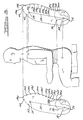
- FIG. 1 is an elevational view of a design template, according to the present invention, illustrated in operational relationship with a seat and having a NEUTRAL posture torso section.
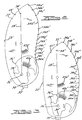
- FIG. 2 is an elevational view of an ERECT posture torso section of the design template of FIG. 1.
- FIG. 3 is an elevational view of a SLUMPED posture torso section of the design template of FIG. 1.
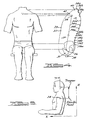
- FIG. 4 is an elevational view of the design template of FIG. 1 relative to a front of a human body occupant.
- FIG. 5 is an elevational view of the design template of FIG. 1 relative to a side of a human body occupant.
- FIG. 6 is an elevational view of a human body occupant illustrating eye location relative to a shoulder point.
- FIG. 7 is an elevational view of a pelvis illustrating angle of pelvic landmarks with respect to lap belt contact points.
- FIG. 8 is an elevational view of the design template of FIG. 1 with an ERECT posture illustrating angle of pelvic landmarks with respect to lap belt contact points.
- FIG. 9 is a view similar to FIG. 8 illustrating a NEUTRAL posture.
- FIG. 10 is a view similar to FIG. 8 illustrating a SLUMPED posture.
- FIG. 11 is an elevational view of the design template of FIG. 1 illustrating shoulder belt positions relative to design template landmarks.
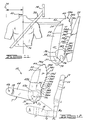
- FIG. 12 is an elevational view of the design template of FIG. 1 and a cross-section of a seat.
- FIG. 13 is a graph that is representative of seat cushion and seat back deformation for 5th percentile female having a NEUTRAL posture.
- FIG. 14 is a graph that is representative of seat cushion and seat back deformation for 50th percentile male having a NEUTRAL posture.
- FIG. 15 is a graph that is representative of seat cushion and seat back deformation for 95th percentile male having a NEUTRAL posture.
- FIG. 16 is an estimated force deflection curve for typical soft, medium and hard seats.
-
- Referring to FIG. 1, one embodiment of a
design template 10, according to the present invention, is illustrated in operational relationship with a seat, generally indicated at 12, of an automotive vehicle (not shown). The automotive vehicle includes afloor pan 14 which includes a toe pan ortoe board 16 adjacent to a front end thereof. Theseat 12 is mounted on thefloor pan 14 by suitable adjustable mounting mechanisms (not shown). Theseat 12 includes aseat cushion 18 to primarily support a torso weight under an ischium of a human body occupant and a weight of a thigh of the human body occupant and a seat back 20 to support a back of the human body occupant primarily in a thoracic and lumbar regions of the human body occupant. It should be appreciated that the design of theseat cushion 18 and seat back 20 will be in accordance with thedesign template 10 to resiliently and comfortably support the human body occupant when seated thereon. - The
design template 10, according to the present invention, is used to design theseat 12. Thedesign template 10 includes at least onetorso section 22. Thetorso sections 22 are dimensionally accurate to simulate or represent body size of a human male who is 95th percentile in weight and stature, a human male who is 50th percentile in weight and stature or a human female who is 5th percentile in weight and stature. It should be appreciated that the 5th percentile female represents the smallest body size while the 95th percentile male represents the largest body size. - In general, the development of the
design template 10 has relied upon the U.S. Public Health Service for height and weight description of the general population and the U.S. military for the anthropometric dimensions of the human body that are used in ergonomic design. Anthropometric surveys, however, measure people in standardized sitting and standing postures. Since the purpose of thedesign template 10 is to represent the human body in anatomically and biomechanically correct sitting postures, additional data had to be collected that would describe the sitting posture of the human body. Sitting posture is primarily a function of torso posture. As a result, an investigation was conducted of torso back shape in different sitting postures. - The results can be divided into two parts: 1) the size and shape of the
torso sections 22 and 2) the size and shape of the leg sections (thigh sections 44, calf sections 52 and shoe sections 62 to be described). The human body was divided into three sizes: small female, average male and large male. The torso was divided into three shapes representing three postures: ERECT, NEUTRAL and SLUMPED. The human body sizes were defined by anthropometric dimensions and regression equations that describe the relationships between the dimensions. The torso shapes were mathematically defined from measurements of subjects in five positions. - In general, spinal, chest, pelvic and extremity landmarks in fifty females and fifty-two males were measured in five postures, ranging from full lumbar extension to fully slouched. Spine height was used to normalize the back curvatures for each subject so that variation in the shape of the back due to size differences was minimized. The data that measures lumbar curvature for each posture was represented by a second order polynomial that was fit to the lumbar spine data and the average lumbar curvatures for each subject in the region bounded by L1 and L5 was calculated. Subjects were used to define the three postures if they had back curvatures within mathematically prescribed limits that define ERECT (lumbar extension with a relative curvature greater than 0.6 radians per spine height), NEUTRAL (straight lumbar spine with a relative curvature between +0.6 and -0.6 radians per spine height) and SLUMPED (lumbar flexion with a relative curvature less than -0.6 radians per spine height).
- In order to obtain an average spinal shape, data from subjects measured were weighted according to their sitting height so that the statistical distribution of measured subjects matched those from the military anthropometric survey. The spinal shapes of the statistically weighted data were then averaged. The average male ERECT postures were then scaled to match the military 50th percentile and 95th percentile cervical sitting height. The average female ERECT posture was scaled to match the
military 5th percentile cervical sitting height. The same scaling factors were applied to the NEUTRAL and SLUMPED spinal shapes. - The pelvis in both males and females is based upon the average pelvis from an FAA pelvic study by Reynolds in 1982. The 95th percentile male pelvis is scaled up from the average male pelvis and the 5th percentile female pelvis is scaled down from the average female pelvis. The position of the pelvis was measured in each posture described above. The three-dimensional coordinates that describe the average pelvis in the FAA skeletal data base are rotated to the same pelvic orientation as the pelvis position in the measured subjects. After orienting the pelvis, the size of the pelvis was scaled to equal the pelvis size of the subjects in the NEUTRAL posture as represented by the distance between the Ischial Tuberosity and S1. The resulting skeletal data are optimally matched for position and size in the measured laboratory subjects. The spine was attached at S1 after correcting for tissue thickness in the pelvis and back.
- The leg sections were defined for each of the three human body sizes: large male, average male and small female. The definition came from anthropometric estimates of the distance between joint centers at the hip, knee and ankle, otherwise referred to as link lengths. The depth of the sections was estimated from anthropometric equations that defined the relationship between human body weight and human body depth. These dimensions were used to assemble the thigh and calf sections to look like human segments for each of the three human body sizes.
- The foot is assumed to be covered by an average shoe size for each of the respective human body sizes. The small female shoe is a size six, the average and large male shoe sizes are ten and twelve, respectively. The location of the ankle joint relative to the shoe was estimated from measurements of live people. It should be appreciated that the above was used to generate the
design template 10. - As illustrated in FIG. 1, the
torso section 22 is for a 50th percentile male with a NEUTRAL posture. FIG. 2 illustrates atorso section 22 for a 50th percentile male with an ERECT posture. FIG. 3 illustrates atorso section 22 for a 50th percentile male with a SLUMPED posture. It should be appreciated that thetorso section 22 can be for either the 95th percentile male or 5th percentile female with either one of a NEUTRAL, ERECT or SLUMPED posture. It is recommended that the seat design process begin with the NEUTRAL posture and proceed to accommodating the ERECT posture while the SLUMPED posture should be supported in every seat, but not encouraged. - The
torso section 22 has anouter contour 23. Theouter contour 23 has aninterface portion 23a conforming to a deformed shape between theseat 12 and a seated human body occupant. Theouter contour 23 also has an anterior portion 23b that is anthropometrically and anatomically correct. - The
torso section 22 is made of any suitable media to represent the torso of a human body occupant. For example, the media may be electronic, paper, wood, plastic or the like. Preferably, thetorso section 22 is a sheet of rigid material such as plastic. Thetorso section 22 is preferably transparent. - Referring to FIGS. 4 through 5, the
torso section 22 includes anatomical details located relative to each other and theinterface contour 23a is located relative to the anatomical details. Thetorso section 22 contains indicia of skeletal landmarks relative to a seated human body occupant. For example, thetorso section 22 includes ashoulder joint 24 and ahip joint 26 and aline axis 28 connected therebetween. Thetorso section 22 includes a centerline projection of a pelvis with indicia representing an ischial tuberosity, anterior superior iliac spine, pelvic symphysis and sacrum. Thetorso section 22 also has a point ID° 30 (FIG. 12) as the lowest point on aischial tuberosity 31 projected to theinterface contour 23a of the occupied seat. Since the majority of torso weight passes through ID 0 30, the area of theseat 12 below this point will have the highest pressure as well as the most deflection. Thetorso section 22 also has spinal landmarks 34 marked along the entire length of the back thereof. The spinal landmarks 34 are important for correctly placing the lumbar support and for adequate design of the chest support for theseat 12. The spinal landmarks 34 are for the neck (cervical spine) indicating C7 at 34a, chest (thoracic spine) indicating T2, T4, T6, T8, T10, T12 at 34b, 34c, 34d, 34e, 34f and 34g, respectively, referred to as point S (FIG. 12), low back (lumbar spine) indicating L1 through L5 at 34h, 34i, 34j, 34k and 341, respectively, referred to as point L (FIG. 12), and sacrum (attaches the spine to the pelvis) indicating S1 at 34m. It should be appreciated that thehip joint 26 is referred to as the H-point in SAE seat design practice. The hip joint is a ball-and-socket joint connecting the thigh to the pelvis of a human body occupant. It should also be appreciated that the anterior shape of thetorso section 22 is anthropometrically and anatomically correct. It should further be appreciated that the location of the hip joint changes with posture. - The
torso section 22 has indicia for the most anterior portion on the top of a pelvis of a human body occupant which is the anterior superior iliac spine (ASIS),point A 36 and a pubic symphysis,point P 38. A lap belt to be described should cross belowpoint A 36 and abovepoint P 38. Thetorso section 22 also has indicia for theshoulder joint 24, neck/shoulder junction,point N 40 and a suprasternal (top of sternum),point SS 42. The shoulder strap should be belowpoint N 40 and aboveshoulder joint 24. - The
torso section 22 includes a firstangular scale 43a for hip angle and a second angular scale 43b for torso angle. A torso bar is connected to thetorso section 22 on the hip joint 26 to shoulderjoint axis 28, 205 mm from thehip joint 26 for alltorso sections 22. The torso bar is connected to thetorso section 22 by a hinge such as a hollow bolt and nut 45b. It should be appreciated that the angle on the second angular scale 43b indicates the angle betweenline axis 28 and vertical as defined by parallel indicia lines on the torso bar. Furthermore, it should be appreciated that the firstangular scale 43a has a range of 45° to 180° with a comfort range of 85° to 125°. It should be appreciated that the second angular scale 43b has a range of -20° to 45° with a comfort range of 10° to 30°. - The
design template 10 also includes at least onethigh section 44. Thethigh sections 44 are dimensionally accurate to simulate or represent human body size of the 95th percentile male, 50th percentile male and 5th percentile female. Thethigh section 44 is made of any suitable media to represent the thigh of a human body occupant. For example, the media may be electronic, paper, wood, plastic or the like. Preferably, thethigh section 44 is a sheet of rigid material such as plastic. Thethigh section 44 is preferably transparent. - The
thigh section 44 is connected to thetorso section 22 at the hip joint 26 by a hinge such as a hollow bolt andnut 45a. Thethigh section 44 includes indicia of thehip joint 26 and a knee joint 46 and aline axis 48 therebetween. Thethigh section 44 also includes anangular scale 50 for knee angle and a pointer 51 for hip angle. It should be appreciated that theangular scale 50 for the knee angle has a range of 45° to 180° with a comfort range of 110° to 140°. It should also be appreciated that the pointer 51 indicates the angle on the firstangular scale 43a for the angle between theline axis 48 andline axis 28. - The
thigh section 44 has a deformed bottom contour 51a representing a change from hard bone tissue to soft muscle tissue in contact with theseat cushion 18. Thethigh section 44 andtorso section 22 are geometrically congruent in a seated posture where they overlap on theseat cushion 18. - The
design template 10 also includes at least one calf section 52. The calf sections 52 are dimensionally accurate to simulate or represent human body size of the 95th percentile male, 50th percentile male and 5th percentile female. The calf section 52 is made of any suitable media to represent the calf of a human body occupant. For example, the media may be electronic, paper, wood, plastic or the like. Preferably, the calf section 52 is a sheet of rigid material such as plastic. The calf section 52 is preferably transparent. - The calf section 52 is connected to the
thigh section 44 at the knee joint 46 by a hinge such as a hollow bolt andnut 45c. The calf section 52 includes indicia of the knee joint 46 and an ankle joint 54 and aline axis 56 therebetween. The calf section 52 also includes indicia of apointer 58 for knee angle and anangular scale 60 for ankle angle. The calf section 52 andthigh section 44 are geometrically congruent in a seated posture where they overlap on anterior and superior contours. It should be appreciated that theangular scale 60 for the ankle angle has a range of 70° to 160° with a comfort range of 85° to 115°. It should also be appreciated that thepointer 58 indicates the angle on theangular scale 50 for the angle of the knee between theline axis 48 andline axis 56. - The
design template 10 further includes at least one shoe section 62. The shoe sections 62 are dimensionally accurate to simulate or represent human shoe size of the 95th percentile male, 50th percentile male and 5th percentile female. The shoe section 62 is made of any suitable media to represent the shoe. For example, the media may be electronic, paper, wood, plastic or the like. Preferably, the shoe section 62 is a sheet of plastic material. The shoe section 62 is preferably transparent. - The shoe section 62 is connected to the calf section 52 at the ankle joint 54 by a hinge such as a hollow bolt and nut 45d. The shoe section 62 includes indicia for the ankle joint 54, a pointer 64 for the ankle angle and a
line axis 65 from a ball of foot to heel of foot inside a shoe. It should be appreciated that the shoe section 62 has a heel. It should also be appreciated that the pointer 64 indicates the angle on theangular scale 60 for the angle of the ankle between theline axis 65 andline axis 56. - Referring to FIGS. 7 through 11, the
torso section 22 contains indicia on the location of landmarks that define the optimal path of a lap belt and a shoulder belt of an occupant restraint system. It should be appreciated that this information is important for lap belt and shoulder belt attachment points relative to differences in the position of theseat 12 and human body occupant size. - The
torso section 22 also has the indicia of the anterior superior iliac spine (ASIS) 66. Thetorso section 22 further has the indicia of anASIS notch 68. It should be appreciated that the lap belt should lie below theASIS 36 of the human body occupant to reduce chances for "submarining" (occupant sliding under the lap belt) in the event of a vehicle collision. - Accordingly, an occupant restraint system, according to the present invention, includes a lap belt anchored to vehicle structure such that it extends below the
ASIS 36 and above theAIIS 66 for thedesign template 10 with thetorso section 22 having the ERECT posture. The occupant restraint system includes ashoulder belt 72 anchored tovehicle structure 74 such that it extends a first predetermined distance from acenterline 76 of theseat 12 to theshoulder joint 24 for thedesign template 10 with thetorso section 22 being either the 5th percentile female, 95th percentile male or a 50th percentile male and a second predetermined distance from the centerline of theseat 12 to the neck/shoulder junction 40 for thedesign template 10 with thetorso section 22 being either the 5th percentile female, 50th percentile male or the 95th percentile male. The first predetermined distance and second predetermined distance are in the following table:Location of shoulder belt for design templates. Design Template 10First Predetermined Distance from Centerline to Shoulder(mm) Second Predetermined Distance from Centerline to base of neck (mm) 5th Percentile Female 190 51 50th Percentile Male 246 65 95th Percentile Male 267 71 - A method, according to the present invention, is disclosed of establishing occupant accommodation criteria in a vehicle package based on a predetermined class of vehicles. The method includes providing the
design template 10 having thetorso section 22 being either the 95th percentile male, 50th percentile male or 5th percentile female with either the ERECT posture, NEUTRAL posture or SLUMPED posture and a corresponding percentile leg section made up of thethigh section 44, calf section 52 and shoe section 62. Within a human body size, the leg sections are the same for all three postures, only the curvature of the spinal column in the centerline differs. The method includes defining an accelerator to provide a heel point of the shoe section 62. The method includes defining deflection of aseat 12 whether it is high deflection (soft), medium deflection (medium) or low deflection (hard). The method also includes positioning thedesign template 10 in the vehicle such that the heel of the shoe section 62 is at the heel point, the bottom of thethigh section 44 under thehip joint 26 is at the seat height, thetorso section 22 is at the torso angle 43b and angles of the leg section are within predetermined conform ranges. The method includes establishing a seat height from a floor to a bottom of thetorso section 22 at ID 0. The method further includes establishing an H-point (Hpt) for eachdesign template 10 and H-point reference point (HptRP) relative to the heel point in a vehicle axis system by thedesign template 10. - The H-point represents the two-dimensional center of rotation of the
hip joint 26 and is located at the center of the hollow nut andbolt 45a. The H-point window in a vehicle package is defined by a polygon that contains the locations of the 5th percentile female, 50th percentile male and 95th percentile male H-points for the range of comfort angles (Table 2) in the ankle, knee and hip joints per vehicle package requirements. The package requirements define an occupant space between thevehicle floorpan 14 and avehicle headliner 70 that determines in large part the space available for theseat 12 and the human body occupant. As the space available for theseat 12 and human body occupant diminish, the mechanical properties of theseat 12 and its geometrical shape and size become more critical in supporting the variety of postures (Table 3) represented by thedesign template 10 for the seat design process. - 1. The method includes the step of adjusting
joint angles at an ankle, knee and hip of the
design template 10 to lie within a predetermined range. For example, adjust linkage joint angles between ankle, knee and hip of thedesign template 10 to lie within predetermined comfort ranges at each joint. Joint angles are laid out on thedesign template 10 at the hip, knee and ankle joints. The design template angles for comfort are defined for the torso, thigh and each of the leg joints within the following ranges (Table 2).Comfort Joint Angles Dimension Definition Design Template 10 Torso Vertical = 0° 10° to 30° Thigh 90°-(Hip-Torso) 5° to 10° Hip Included Angle 85° to 125° Knee Included Angle 110° to 140° Ankle Included Angle 85° to 115° - 2. The method includes the step of reclining
the torso section 22 a predetermined angle from
vertical. The torso angle for the seat back 20 is
defined with vertical at zero. For example, recline the
torso section 22 from vertical according to thedesign template 10 posture as follows (Table 3):Torso back angles for the design templates per posture group. Posture Recommended Angle Angle Range ERECT 10° 8° - 14° NEUTRAL 18° 14° - 22° SLUMPED 26° 20° - 28° -
- The x displacement (i.e., fore-aft direction) is defined by the location of H-points in the vehicle x direction from the 5th percentile female to the 95th percentile male. Ankle angle, accelerator pedal orientation, and length of the leg are the most important parameters in this packaging dimension. Comfort angles (Table 2) at the knee vary according to seat height packaging. As the seat height (i.e., SE H61) space rises, the comfort angle of the knee used to define x-displacement of the
seat 12 decreases. As the seat height space decreases, the comfort angle of the knee used to define x-displacement of theseat 12 increases. If comfort angle of the ankle remains in the 85° to 90° range and the thigh angle with horizontal remains in the 5° to 10° range, the horizontal seat travel is large and well-defined. - The z displacement (i.e., vertical direction) is defined by the location of H-points in the vehicle z direction from the 95th percentile male to the 5th percentile female. Posture varies according to packaging volume and occupant preference, but in general, the method includes locating an eye relative to a shoulder joint such that seat travel accommodates eye location (Table 4) for all human body occupants in all postures. As the seat height (i.e., SE H61) space decreases, a SLUMPED posture becomes more likely in the human body occupant. As the seat height space increases, an ERECT posture becomes more likely in the human body occupant. The vision needs of different size human body occupants and the amount of headroom in the vehicle package largely determine seat travel in this direction.
Location of Eye relative to shoulder joint in design template 10.Design Template 10Horizontal (X) mm (Forward) Vertical (Z) mm (Above) 5th Percentile Female 52 186 50th Percentile Male 63 205 95th Percentile Male 69 212 - The location of the heel is determined by ankle angle and accelerator-foot axis orientation. The prescribed ankle angle lies between 85° and 90° with the shoe section 62 positioned so that the
foot axis 65 is parallel to the undepressed accelerator (o mph) pedal. - 1. A method for establishing occupant
accommodation in a vehicle package, according to the
present invention, is disclosed. In general, the method
includes the steps of selecting in a logical sequence at
least one
design template 10 having atorso section 22 being one of a 95th percentile male, 50th percentile male, and a 5th percentile female having either an ERECT posture, a NEUTRAL posture, or SLUMPED posture and having a leg section. The leg section is made up of thethigh section 44, calf section 52 and shoe section 62. The method also includes the step of marking the location of heel point and H-point. - 2. The method includes the step of
positioning the heel of the shoe section 62 on the
floorpan 14 with thefoot axis 65 of the shoe section 62 parallel to the undepressed (0 mph) accelerator pedal axis. Forcing the foot axis to remain parallel to the accelerator pedal may place the knee and hip joints outside their range of seating comfort. However, adjusting the foot axis so that the angle is 10° from the accelerator pedal line provides for a wider range of positions while maintaining joint angles within their comfort range. This adjustment is best because it represents the compensational change in ankle angle brought about by leg splay and calf rotation in the actual vehicle package. - 3. The method includes the step of locating
the center of the hip joint 26 to define the H-point for
the 95th percentile male (Hpt95). Since the
design template 10 represents the human body occupant in a seat, the vertical and horizontal location of Hpt95 is defined in an occupied seat of a vehicle package based on a predetermined class of vehicles for thedesign template 10 of the 95th percentile male. The horizontal location of Hpt95 in the vehicle package is defined by the position of the heel on thefloorpan 14 and the comfort angles (Table 2) of the ankle, knee, and thigh that control the relative orientations of the shoe section 62, calf section 52 andthigh section 44 of thedesign template 10 of the 95th percentile male. The vertical location of Hpt95 is defined by the height from thefloorpan 14 to center of the circle defined by the hollow bolt andnut 45a of thedesign template 10 of the 95th percentile male. Since the forces on the occupied seat under H-point at ID o are determined by torso size and torso angle, the vertical space in the centerline of the seat available for supporting seat structures is defined by the vertical height of theinterface portion 23a of the outer contour of thedesign template 10 from thefloorpan 14. Torso angle is selected to accommodate eye vision and head clearance of the 95th percentile male in the vehicle package based on the height available in a predetermined class of vehicles from thefloorpan 14 to theheadliner 70. After optimally positioning thedesign template 10 of the 95th percentile male, trace the center circle of the hollow bolt andnut 45a to define the Hpt95 that is the center of the circle of thedesign template 10 of the 95th percentile male having one of the ERECT posture, NEUTRAL posture or SLUMPED posture. Record the posture selected for defining Hpt95. - 4. The method includes the step of
positioning the heel of the shoe section 62 for the
design template 10 of the 5th percentile female having one of the ERECT posture, NEUTRAL posture or SLUMPED posture in the vehicle package. Since thedesign template 10 represents the human body occupant in a seat, the vertical and horizontal location of the H-point for the 5th percentile female (Hpt5) is defined in an occupied seat of a vehicle package based on a predetermined class of vehicles for thedesign template 10 of the 5th percentile female. The horizontal location of Hpt5 in the vehicle package is defined by the position of the heel on thefloorpan 14 and the comfort angles (Table 2) of the ankle, knee, and thigh that control the relative orientations of the shoe section 62, calf section 52 andthigh section 44 of thedesign template 10 of the 5th percentile female. The vertical location of Hpt5 is defined by the height from thefloorpan 14 to center of the circle defined by the hollow bolt andnut 45a of thedesign template 10 of the 5th percentile female. Since the forces on the occupied seat under H-point at ID o are determined by torso size and torso angle, the vertical space in the centerline of the seat available for supporting seat structures is defined by the vertical height of theinterface portion 23a of the outer contour of thedesign template 10 from thefloorpan 14. Torso angle is selected to accommodate eye vision and head clearance of the 5th percentile female in the vehicle package based on the height available in a predetermined class of vehicles from thefloorpan 14 to theheadliner 70. After optimally positioning thedesign template 10 of the 5th percentile female, trace the center circle of the hollow bolt andnut 45a to define the Hpt5 that is the center of the circle of thedesign template 10 of the 5th percentile female having one of the ERECT posture, NEUTRAL posture or SLUMPED posture. Record the posture selected for defining Hpt5. - 5. The method includes the step of
positioning the heel of the shoe section 62 for the
design template 10 of the 50th percentile male having one of the ERECT posture, NEUTRAL posture or SLUMPED posture in the vehicle package. Since thedesign template 10 represents the human body occupant in a seat, the vertical and horizontal location of the H-point for the 50th percentile male (Hpt50) is defined in an occupied seat of a vehicle package based on a predetermined class of vehicles for thedesign template 10 of the 50th percentile male. The horizontal location of Hpt50 in the vehicle package is defined by the position of the heel on thefloorpan 14 and the comfort angles (Table 2) of the ankle, knee, and thigh that control the relative orientations of the shoe section 62, calf section 52 andthigh section 44 of thedesign template 10 of the 50th percentile male. The vertical location of Hpt50 is defined by the height from thefloorpan 14 to center of the circle defined by the hollow bolt andnut 45a of thedesign template 10 of the 50th percentile male. Since the forces on the occupied seat under H-point at ID o are determined by torso size and torso angle, the vertical space in the centerline of the seat available for supporting seat structures is defined by the vertical height of theinterface portion 23a of the outer contour of thedesign template 10 from thefloorpan 14. Torso angle is selected to accommodate eye vision and head clearance of the 50th percentile male in the vehicle package based on the height available in a predetermined class of vehicles from thefloorpan 14 to theheadliner 70. After optimally positioning thedesign template 10 of the 50th percentile male, trace the center circle of the hollow bolt andnut 45a to define the Hpt50 that is the center of the circle of thedesign template 10 of the 50th percentile male having one of the ERECT posture, NEUTRAL posture or SLUMPED posture. Record the posture selected for defining Hpt50. - 6. The method includes the step of
constructing a line parallel to a travel axis of a seat
track in the vehicle package. After considering seat
deflection for each of the
above design templates 10, construct a line that best fits the location of each H-point for thedesign template 10 of the 5th percentile female, 50th percentile male and 95th percentile male. - 7. A method to define a H-point Reference
Point (HptRP) that is at the rearmost and downmost
position of the
seat 12 in the vehicle package is disclosed. Hpt95 and HptRP may be coincidental. After optimally defining the travel axis of the seat track, the line parallel to the travel axis of the seat track may be extended rearward to accommodate a larger human occupant. The direction that the track is extended depends upon the type of seat, whether manual or power adjustments are used, and the position and orientation of the seat track that accommodates the 5th percentile female and 50th percentile male. -
- A method for designing a seat, according to the present invention, is disclosed. In general, the method includes the steps of selecting at least one
design template 10 having atorso section 22 being one of the 95th percentile male, 50th percentile male and 5th percentile female having either the ERECT posture, NEUTRAL posture or SLUMPED posture and having a leg section. The leg section is made up of thethigh section 44, calf section 52 and shoe section 62. The method also includes the step of forming load supporting contours and unloaded contours of theseat 12 for at least onedesign template 10. The forces acting on the occupied (°)seat 12 are distributed into load support points in eachdesign template 10 that are used to define the thorax (S°), lumbar (L°), ischium (ID°) and thigh (T°) load support points (FIG. 12) in theseat 12. - For example, select the
design template 10 of the 95th percentile male having the NEUTRAL posture with the leg section attached. After using the NEUTRAL posture, proceed to accommodating the ERECT posture. The SLUMPED posture should be supported in everyseat 12, but not encouraged by any poor design effects in theseat 12. - The orientation of the pelvis changes with each of the three postures. In the ERECT posture, the pelvis is rotated forward so that the D-point is closer to the most anterior point on the ischium (I1). In the SLUMPED posture, the pelvis is rotated rearward so that D-point is closer to the most posterior point on the ischium (I2). Thus, as the orientation of the pelvis changes with posture, critical design landmarks, i.e., D-point, change their location.
- In the ERECT posture, the position of the tip of the sacrum is above the occupied seat contour so that the contour from bite line to D-point is not contacted. In the SLUMPED posture, the position of the tip of the sacrum is close to the occupied seat contour so that the
seat 12 from D-point to bite line should not rise, but slope downward to reduce pressure on the sacrum. - 1. The method includes the step of tracing
the
interface contour 23a of thedesign template 10 of the 95th percentile male having the NEUTRAL posture. After optimally adjusting the template heel point, H-point and comfort angles (Tables 1 and 2), trace theinterface contour 23a, marking all landmarks. - 2. The method also includes the step of
estimating a first point on the occupied seat interface
contour at S° on the
design template 10 under occupant load. For example, in the 95th percentile male having the ERECT posture, mark S° (FIG. 12) at T6 (34d) by constructing the shortest line between the center of the vertebral hole and theinterface contour 23a line. Mark the intersection of the two lines to represent the thorax load support point S°. - 3. The method also includes the step of estimating a second point on the unoccupied seat interface contour at SU. For example, estimate the deflection at S° by using the appropriate value from FIGS. 13 through 16. The displacement of S° to SU is normal to the tangent at the T6 back contour point in the 95th percentile male having the NEUTRAL posture.
- 4. The method also includes the step of
estimating a first point on the occupied seat interface
contour at L° on the
design template 10 under occupant load. For example, in the 95th percentile male having the ERECT posture mark L° (FIG. 12) at L3 (34j) by constructing the shortest line between the center of the vertebral hole and theinterface contour 23a line. Mark the intersection of the two lines to represent the lumbar load support point L°. - 5. The method also includes the step of
estimating a second point on the unoccupied seat
interface contour at LU. For example, by using the
appropriate value from FIGS. 13 through 15, estimate the
deflection at L°. The displacement of L° to LU is normal
to the tangent at the L3 back contour point. In the
ERECT posture for a seat back without an adjustable
lumbar support, LU should contact but not deflect the
seat back 20. In the NEUTRAL posture, LU should be
deflected in the seat back 20. In the SLUMPED posture,
the
design template 10 should not make contact with the seat back 20 at LU. - 6. The method includes the step of
estimating a first point on the occupied seat interface
contour at ID° on the
design template 10 under occupant load. The ID° is the lowest tangential point under the ischium projected onto theinterface contour 23a. - 7. The method includes the step of estimating a second point on the unoccupied seat interface contour at ID U. For example, estimate the undeflected ID U by adding the appropriate value (e.g., FIGS. 14 through 16 for the NEUTRAL posture) to the vertical dimension of the deflected ID°.
- 8. The method includes the step of
estimating a first point on the occupied seat interface
contour at T° on the
design template 10 under occupant load. Mark the thigh center of gravity on thethigh link axis 48, 4/9's of the thigh link length from the hip joint, and construct a line vertically downward (parallel to the gravity vector) to the contour on the thigh. The intersection of these two lines represents T° (FIG. 12). - 9. The method includes the step of
estimating a second point on the unoccupied seat
interface contour at TU. For example, at T°, construct
a circle with a radius equal to the thigh deflection
value from FIG. 16 where thigh weight for each human
body is found in Table 5. Mark the point at the highest
horizontal tangent to the circle about the deflected TU
point. Record the coordinates of highest tangential
point. This point is the undeflected TU for the
seat cushion 18.Seat Cushion Design Parameters for 3 Template Body Sizes. DESIGN PARAMETER S OCCUPANT DIMENSION 5th Percentile Female 50th Percentile Male 95th Percentile Male Occupant Support Surface Contact Width Anthropmerry: Hip Width Leg Splay Leg Splay Thigh CG from Hpt 162 mm 189 mm 207 mm Cushion Deflection Thigh Weight 4.0 kg (8.8 lbs) 6.2 kg (13.6 lbs) 8.0 kg (17.6 lbs) Seat Deflection FIG 16 FIG 16 FIG 16 - 10. The method includes the step of plotting
locations of SU, LU, ID U, and TU to form the unloaded
contour of the
seat 12 with thedesign template 10. - 11. The method includes the step of optimally
matching the unoccupied load support points (SU, LU, ID U,
and TU) for the
other design templates 10 and postures to define the free, unoccupied contour in theseat 12. - 12. The method also includes the step of
defining the unoccupied load support zone for the
thorax. The highest and lowest unoccupied load support
points (SU) from all
design templates 10 define the area of the unoccupied free contour for the thorax in theseat 12. In general, SU at T6 (34d) in the 95th percentile male having the ERECT posture and T10 (34f) in the 5th percentile female having the SLUMPED posture define the limits. Record the coordinates of these points in the vehicle axis system and construct a best fit line to represent the free, unoccupied seat contour for the thorax. - 13. The method also includes the step of
defining the free, unoccupied seat contour for the
lumbar. The highest and lowest unoccupied points (LU)
from all appropriate design template contours define the
area of the lumbar load support zone. The height
locations define the location and range of adjustment
needed for lumbar support, if required. Some seat
deflections may permit the definition of a fixed lumbar
support that may be built into the
seat 12 or a two-way adjustable lumbar support in the fore-aft direction. Record the coordinates of these points in the vehicle axis system and construct a best fit line to represent the free, unoccupied seat contour for the lumbar. - 14. The method also includes the step of
defining the free, unoccupied seat contour for the
ischium, i.e., butt pocket. The furthest forward and
the furthest rearward unoccupied support points (ID U)
from all
design templates 10 define the area of the free, unoccupied seat contour at the butt pocket in theseat cushion 18. Record the coordinates of the ID U points in the vehicle axis system and construct a best fit line to define the unoccupied load support zone for the ischium. - 15. The method also includes the step of
defining the area for the seat suspension in the
seat 12. The furthest forward and the furthest rearward ischial load points (ID°) from alldesign templates 10 determine the area for the seat suspension. In general, the 95th percentile male having the SLUMPED posture and the 5th percentile female having the ERECT posture define the limits. Record the coordinates of the ID° points in the vehicle axis system and construct a best fit line to define the occupied load support zone for the ischium. - 16. The method also includes the step of
defining the free, unoccupied seat contour for the
thigh. The furthest forward and furthest rearward
unoccupied points in the thigh (TU) from all
design templates 10 determine the area for the unoccupied thigh support zone. The method includes the step of constructing a free seat contour through TU for each of thedesign templates 10. For example, compare the results at TU between thedesign templates 10 of the 5th percentile female and the 95th percentile male. The distance between the extreme locations should define the seat cushion bolster region. Record the coordinates of these points in the vehicle axis system and construct a best-fit line to represent the unoccupied load support zone for the thigh. - 17. The method also includes the step of
defining the waterfall region of the
unoccupied seat 12. The waterfall at this bolster region should be designed so that the contour from TU to the edge of theseat 12 diminishes with only trim contacting the back of the calf in the seateddesign template 10 of the 5th percentile female having the ERECT posture. Record the coordinates of these points in the vehicle axis system and construct a best fit line to represent the unoccupied load support zone for the thigh. -
- The
seat 12 is composed of two structural members: (1) aseat cushion 18 that primarily supports the human body occupant's torso weight under the ischium and the weight of the human body occupant's thigh, and (2) a seat back 20 that supports the human body occupant's back primarily in the thoracic and lumbar regions. Theseat cushion 18 is typically composed of five primary structures: a) upholstery or trim, typically a woven cloth material or leather; b) deformable pad, typically foam; c) a suspension under the butt pocket, typically metal springs attached to metal wires and/or straps; d) an anti-submarining region forward of the suspension; and e) a rigid frame, typically sheet metal with sufficient shape and strength to support the human body occupant load. The seat back 20 is typically composed of four primary structures and one optional structure: a) upholstery or trim, typically a woven cloth material or leather covering of the seat back 20; b) deformable pad, typically foam; c) a rigid frame, typically a tube of metal in an inverted U-shape; d) a structural cross member spanning the vertical frame near the base of the seat back 20 to prevent occupant penetration of the seat back 20 in a vehicle collision; and e) an optional lumbar support, typically a deformable basket or inflatable bag(s) support the lumbar region of the human body occupant. - The
design templates 10 are used to define the loaded contours of theseat 12 and the location of supporting and restraining structures, or their absence, as required for different postures and different body sizes. Thedesign templates 10 are positioned relative to preferred torso angles (Tables 2 and 3). In general, the ERECT posture will sit in a range from 8° to 14°, NEUTRAL in a range from 14° to 22° and SLUMPED in a range from 20° to 28°. The ID point lies on an inclined plane that is defined by the change in weight transmitted from theseat cushion 18 to the seat back 20 as the human body occupant changes postures from ERECT to SLUMPED. The inclination of theseat cushion 18 is defined by thigh angle (Table 2). - A method, according to the present invention, is disclosed of using the
design template 10 to design theseat 12 for a motor vehicle. In general, the method includes the steps of providing thedesign template 10 having thetorso section 22 being one of a group comprising the 95th percentile male, 50th percentile male and 5th percentile female having either an ERECT posture, a NEUTRAL posture or a SLUMPED posture. The method includes the steps of establishing occupant accommodation criteria in a vehicle package based on a predetermined class of vehicles and positioning thedesign template 10 in a vehicle to define seat height and seat track displacement to accommodate eachdesign template 10 on aseat 12 having aseat cushion 18 and a seat back 20 in a vehicle representing the vehicle package criteria. The method also includes the step of defining at least one from a group comprising unloaded contours on the seat at SU, LU, ID U and TU. The method further includes the step of defining at least one from a group comprising a seat back height, seat cushion length, head restraint position, thorax support, lumbar support, seat back bite line region, seat cushion bite line region, seat cushion bolster (e.g., waterfall region) and seat suspension for theseat 12 relative to thedesign template 10. - The method includes the step of defining a seat back height for the seat relative to the
design template 10. - 1. Seat back height should not exceed T2u on
the
torso section 22 of the 50th percentile male having the ERECT posture. - 2. The top cross member of the seat back
frame should not be lower than T4° on the
torso section 22 of the 50th percentile male having the ERECT posture. -
- The method includes the step of defining a head restraint position for the
seat 12 relative to thedesign template 10. - 1. The back of the head for the
torso section 22 of the 95th percentile male having the ERECT posture defines the lowest maximum height of the head restraint. - 2. The back of the head for the
torso section 22 of the 95th percentile male having the ERECT posture is 170 mm behind the eye. - 3. The eye is calculated according to the procedure described previously (Table 4 and FIG. 6).
-
- The method includes the step of defining a thorax support for the
seat 12 relative to thedesign template 10. - 1. The highest and lowest thorax load points
(Su) from all design template contours define the area of
thorax support. In general, Su at T6 in the 95th
percentile male having the ERECT posture and T10 in the
5th percentile female having the SLUMPED
posture design templates 10 define the limits. -
- The method includes the step of defining a lumbar support for the
seat 12 relative to thedesign template 10. - 1. Structural mechanics of the seat back
deformable pad designed so that the pad bends easily at
T12° for the
torso section 22 of the 95th percentile male having the ERECT posture and at S1° for thetorso section 22 of the 95th percentile male having the ERECT posture. - 2. The horizontal displacement of an
adjustable lumbar support should lie at L° between L3
and L4 for the
torso section 22 of the 95th percentile male having the ERECT posture. - 3. The vertical displacement of an
adjustable lumbar support should lie at L° between L2
and L5 for the
torso section 22 of the 95th percentile male having the ERECT posture. -
- The method includes the step of defining a seat back bite line region for the
seat 12 relative to thedesign template 10. - 1. Structure in the seat back 20 to restrain
rearward motion of the human body occupant into the seat
back 20 should lie within the region bounded by S1 for
the
torso section 22 of the 95th percentile male having the ERECT posture and S1 for thetorso section 22 of the 5th percentile female having the NEUTRAL posture. - 2. No non-deformable structures should be
placed in the seat back 20 below S1 for the
torso section 22 of the 5th percentile female having the NEUTRAL posture. -
- The method includes the step of defining a seat cushion bite line region for the
seat 12 relative to thedesign template 10. - 1. Non-deformable structures should not rise above the horizontal tangent at the ID° contour of the 95th percentile male having the ERECT posture.
- 2. Non-deformable structures should not be
placed further forward in the
seat cushion 18 than a line formed tangent to S° and L° on theinterface contour 23a of the 95th percentile male having the ERECT posture. -
- The method includes the step of defining a seat suspension for the
seat 12 relative to thedesign template 10. - 1. The furthest forward and the furthest
rearward ischial load points ID° for the
torso section 22 from alldesign templates 10 determine the area for the seat suspension. In general, thedesign templates 10 for the 95th percentile male having the SLUMPED posture and the 5th percentile female having the ERECT posture define the limits. - 2. The suspension accommodates the range in 1 above when designed from a vertical line passing through H-point in the 95th percentile male having the NEUTRAL posture to extend forward 170 mm to the 95th percentile male having the SLUMPED posture ID° point and rearward 30 mm to the 5th percentile female having the ERECT posture ID° point.
- 3. The forces on the seat suspension are
determined from the torso angle for each design template
10 (FIGS. 13 through 16). The force-deflection
characteristics of the suspension are estimated using
the relative deflection for each
design template 10. -
- The method includes the step of defining a region in the forward part of the
seat cushion 18 that prevents forward motion of the pelvis in a vehicle collision. - 1. The anti-submarining region in the
seat cushion 18 lies between the most forward point of the seat suspension and the frame of theseat 12 at the nose of theseat cushion 18. In general, this anti-submarining region does not support vertical loads from human body weight but acts to restrain the forward horizontal motion of the human body occupant in a collision environment. It is therefore, important, that the anti-submarining region have low resistance to vertical loads. - 2. In addition, the anti-submarining region
in the
seat cushion 18 has a vertical barrier in the seat frame at the nose of theseat cushion 18 to prevent horizontal motion of theischium 30 of thedesign template 10 past the nose of theseat cushion 18. Thedesign template 10 for the 5th percentile female having the ERECT posture determines the minimum height of this vertical barrier in the seat frame. - 3. The forces on the vertical barrier are determined by the impact conditions and the size of the human body occupant. Thus, the structural materials and their strength must comply with any federal or state regulations concerning forces acting on the restraint system in a motor vehicle.
-
- The method includes the step of defining a seat cushion length for the
seat 12 relative to thedesign template 10. - 1. Construct a circle about the occupied
seat point ID° on the 95th percentile male having the
ERECT posture with a 385 mm radius to define the maximum
length of the
seat cushion 18. Seat cushion length should not exceed the distance from the 5th percentile female having the ERECT posture ID point to a vertical line passing through the 5th percentile female having the NEUTRAL posture knee point with the thigh axis (from Hip joint to Knee point) parallel to the deformed seat contour line. -
- The present invention has been described in an illustrative manner. It is to be understood that the terminology which has been used is intended to be in the nature of words of description rather than of limitation.
- Many modifications and variations of the present invention are possible in light of the above teachings. Therefore, within the scope of the appended claims, the present invention may be practiced other than as specifically described.
Claims (5)
- A design template comprising:a torso section being one of a group comprising a 95th percentile male, 50th percentile male and 5th percentile female characterised by having each being one of a group comprising an ERECT posture, a NEUTRAL posture and a SLUMPED posture, und in that said torso section includes indicia of spinal landmarks marked along a back portion thereof.
- A design template according to claim 1, including one or more of the following features:-(i) wherein said torso has a portion of an outer contour (23) conforming to a deformed shape of an interface contour (23a) between a seat (12) and a seated occupant;(ii) wherein said torso is made of a sheet of a rigid material or represented in electronic media;(iii) wherein said torso includes indicia of skeletal landmarks for a shoulder joint (24) and hip joint (26) and an axis (28) connected therebetween;(iv) wherein said torso includes a centerline projection of a pelvis with indicia representing an ischial tuberosity (31), anterior superior iliac spine (36), pubic symphysis (38) and sacrum (34m);(v) wherein said torso includes an angular scale (43b) for torso angle;(vi) wherein said torso includes an angular scale (43a) for hip angle;(vii) wherein said torso has an anterior shape that is anthropometrically and anatomically correct;(viii) wherein said torso includes indicia for a shoulder joint (24), neck/shoulder junction (40) and a sternum (42); or(ix) a thigh section (44)connected to said torso.
- A design template according to claim 2, including one or more of the following features:(i) wherein said torso includes anatomical details located relative to each other and the interface contour is located relative to said anatomical details;(ii) wherein said thigh section is one of a group comprising a 95th percentile male, 50th percentile male and 5th percentile female;(iii) wherein said thigh section is made of a sheet of rigid material or represented in electronic media;(iv)a hinge (45a) at a hip joint to connect said thigh section to said torso.(v) wherein said thigh section includes indicia of a hip joint and knee joint (46) and an axis (48) therebetween;(vi) wherein said torso and said thigh section are geometrically congruent in a seated posture where they overlap on a seat cushion (18);(vii) wherein said thigh section has a deformed bottom contour (51a) representing a change from hard bone tissue to soft muscle tissue in contact with a seat cushion;(viii) wherein said thigh section includes indicia of a pointer (51) for hip angle and an angular scale (50) for knee angle; or(ix) a calf section (52) connected to said thigh section.
- A design template according to claim 3, including one or more of the following features:-(i) wherein said calf section is one of a group comprising a 95th percentile male, 50th percentile male and 5th percentile female;(ii) wherein said calf section is made of a sheet of rigid material or represented in electronic media;(iii) a hinge (45c) at a knee joint to connect said calf section to said thigh section;(iv) wherein said calf section includes indicia of a knee joint (46) and ankle joint (54) and an axis (56) therebetween;(v) wherein said calf section includes indicia of a pointer (58) for knee angle and a scale (60) for ankle angle;(vi) wherein said calf section and thigh section are geometrically congruent in a seated posture where they overlap on anterior and superior surfaces; or(vii) a shoe section (62) connected to said calf section.
- A design template according to claim 4, including one or more of the following features:(i) wherein said shoe section is one of a group comprising a 95th percentile male, 50th percentile male and 5th percentile female;(ii) wherein said shoe section is made of a sheet of rigid material or represented in electronic media;(iii) a hinge (45d) at an ankle joint to connect said shoe section to said calf section;(iv) wherein said shoe section includes indicia for an ankle joint and a pointer (64) for an ankle angle; or(v) wherein said shoe section has an axis (65) from a ball of foot to heel of foot inside a shoe.
Applications Claiming Priority (3)
| Application Number | Priority Date | Filing Date | Title |
|---|---|---|---|
| US08/949,213 US6840125B1 (en) | 1996-12-09 | 1997-10-10 | Design template |
| PCT/US1998/016846 WO1999019708A1 (en) | 1997-10-10 | 1998-08-13 | Template for designing human seating accomodations |
| US949213 | 2001-09-07 |
Publications (3)
| Publication Number | Publication Date |
|---|---|
| EP1019693A1 EP1019693A1 (en) | 2000-07-19 |
| EP1019693A4 EP1019693A4 (en) | 2001-02-07 |
| EP1019693B1 true EP1019693B1 (en) | 2005-07-20 |
Family
ID=25488757
Family Applications (1)
| Application Number | Title | Priority Date | Filing Date |
|---|---|---|---|
| EP98940883A Expired - Lifetime EP1019693B1 (en) | 1997-10-10 | 1998-08-13 | Template for designing human seating accomodations |
Country Status (4)
| Country | Link |
|---|---|
| EP (1) | EP1019693B1 (en) |
| AU (1) | AU8906198A (en) |
| DE (1) | DE69830913T2 (en) |
| WO (1) | WO1999019708A1 (en) |
Cited By (1)
| Publication number | Priority date | Publication date | Assignee | Title |
|---|---|---|---|---|
| US9821688B2 (en) | 2014-10-02 | 2017-11-21 | Ford Global Technologies, Llc | Rear seat cushion with H-point articulation |
Families Citing this family (25)
| Publication number | Priority date | Publication date | Assignee | Title |
|---|---|---|---|---|
| FR2850942B1 (en) * | 2003-02-11 | 2006-02-17 | Renault Vehicules Ind | CABIN WITH DRIVING STATION FOR MOTOR VEHICLE |
| DE102005048536B4 (en) * | 2005-10-11 | 2007-03-29 | Daimlerchrysler Ag | Method and apparatus for testing a vehicle design model |
| US8801102B2 (en) | 2010-07-30 | 2014-08-12 | Herman Miller, Inc. | Test device for seating structure |
| EP2545943A1 (en) | 2011-07-12 | 2013-01-16 | Dr. Suwelack Skin & Health Care AG | Perforated, coated wound healing material |
| US9415713B2 (en) | 2013-01-24 | 2016-08-16 | Ford Global Technologies, Llc | Flexible seatback system |
| US9409504B2 (en) | 2013-01-24 | 2016-08-09 | Ford Global Technologies, Llc | Flexible seatback system |
| US9399418B2 (en) | 2013-01-24 | 2016-07-26 | Ford Global Technologies, Llc | Independent cushion extension and thigh support |
| US9421894B2 (en) | 2014-04-02 | 2016-08-23 | Ford Global Technologies, Llc | Vehicle seating assembly with manual independent thigh supports |
| US9789790B2 (en) | 2014-10-03 | 2017-10-17 | Ford Global Technologies, Llc | Tuned flexible support member and flexible suspension features for comfort carriers |
| US10046682B2 (en) | 2015-08-03 | 2018-08-14 | Ford Global Technologies, Llc | Back cushion module for a vehicle seating assembly |
| US9994135B2 (en) | 2016-03-30 | 2018-06-12 | Ford Global Technologies, Llc | Independent cushion thigh support |
| US9802512B1 (en) | 2016-04-12 | 2017-10-31 | Ford Global Technologies, Llc | Torsion spring bushing |
| US9845029B1 (en) | 2016-06-06 | 2017-12-19 | Ford Global Technologies, Llc | Passive conformal seat with hybrid air/liquid cells |
| US9849856B1 (en) | 2016-06-07 | 2017-12-26 | Ford Global Technologies, Llc | Side airbag energy management system |
| US9834166B1 (en) | 2016-06-07 | 2017-12-05 | Ford Global Technologies, Llc | Side airbag energy management system |
| US10377279B2 (en) | 2016-06-09 | 2019-08-13 | Ford Global Technologies, Llc | Integrated decking arm support feature |
| US10166894B2 (en) | 2016-06-09 | 2019-01-01 | Ford Global Technologies, Llc | Seatback comfort carrier |
| US10166895B2 (en) | 2016-06-09 | 2019-01-01 | Ford Global Technologies, Llc | Seatback comfort carrier |
| US10286824B2 (en) | 2016-08-24 | 2019-05-14 | Ford Global Technologies, Llc | Spreader plate load distribution |
| US10279714B2 (en) | 2016-08-26 | 2019-05-07 | Ford Global Technologies, Llc | Seating assembly with climate control features |
| US10239431B2 (en) | 2016-09-02 | 2019-03-26 | Ford Global Technologies, Llc | Cross-tube attachment hook features for modular assembly and support |
| US10391910B2 (en) | 2016-09-02 | 2019-08-27 | Ford Global Technologies, Llc | Modular assembly cross-tube attachment tab designs and functions |
| US9914378B1 (en) | 2016-12-16 | 2018-03-13 | Ford Global Technologies, Llc | Decorative and functional upper seatback closeout assembly |
| US10596936B2 (en) | 2017-05-04 | 2020-03-24 | Ford Global Technologies, Llc | Self-retaining elastic strap for vent blower attachment to a back carrier |
| CN114861328A (en) * | 2022-06-13 | 2022-08-05 | 岚图汽车科技有限公司 | Seat stroke setting method and system |
Family Cites Families (7)
| Publication number | Priority date | Publication date | Assignee | Title |
|---|---|---|---|---|
| US3147617A (en) * | 1961-02-06 | 1964-09-08 | Gen Motors Corp | Accommodation checking device |
| GB986093A (en) * | 1964-01-23 | 1965-03-17 | Ford Motor Co | Seats and devices for use in their development |
| US3841654A (en) * | 1972-09-21 | 1974-10-15 | Allied Chem | Vehicle safety system |
| US4335918A (en) * | 1980-09-10 | 1982-06-22 | Bsg International Limited | Vehicle safety seat |
| US4669302A (en) * | 1985-04-24 | 1987-06-02 | Sealy, Incorporated | Deflection and topography assessment mechanism anthropomorphically natural |
| US5456019A (en) * | 1994-04-20 | 1995-10-10 | Lear Seating Corporation | Method and apparatus for measuring a vehicle seat H-point |
| US5483825A (en) * | 1994-10-03 | 1996-01-16 | Ford Motor Company | Accelerator pedal system performance measurement apparatus |
-
1998
- 1998-08-13 EP EP98940883A patent/EP1019693B1/en not_active Expired - Lifetime
- 1998-08-13 DE DE69830913T patent/DE69830913T2/en not_active Expired - Lifetime
- 1998-08-13 AU AU89061/98A patent/AU8906198A/en not_active Abandoned
- 1998-08-13 WO PCT/US1998/016846 patent/WO1999019708A1/en not_active Ceased
Cited By (1)
| Publication number | Priority date | Publication date | Assignee | Title |
|---|---|---|---|---|
| US9821688B2 (en) | 2014-10-02 | 2017-11-21 | Ford Global Technologies, Llc | Rear seat cushion with H-point articulation |
Also Published As
| Publication number | Publication date |
|---|---|
| WO1999019708A1 (en) | 1999-04-22 |
| EP1019693A1 (en) | 2000-07-19 |
| EP1019693A4 (en) | 2001-02-07 |
| DE69830913T2 (en) | 2006-04-20 |
| DE69830913D1 (en) | 2005-08-25 |
| AU8906198A (en) | 1999-05-03 |
Similar Documents
| Publication | Publication Date | Title |
|---|---|---|
| US7347114B2 (en) | Template | |
| US7047831B2 (en) | Design template | |
| EP1019693A1 (en) | Template for designing human seating accomodations | |
| Reed et al. | Effects of vehicle interior geometry and anthropometric variables on automobile driving posture | |
| Park et al. | The evaluation of seating comfort by the objective measures | |
| WO2019208764A1 (en) | Ecu device, vehicle seat, system for estimating lower limb length of seated person, and attachment structure for sitting height detection sensor | |
| Manary et al. | Evaluation of the SAE J826 3-D manikin measures of driver positioning and posture | |
| Hubbard et al. | New biomechanical models for automobile seat design | |
| Reed et al. | Assessing child belt fit, volume I: effects of vehicle seat and belt geometry on belt fit for children with and without belt positioning booster seats | |
| EP1033563A2 (en) | Apparatus for simulating human vibration response | |
| US7797138B2 (en) | System and method for designing a seat | |
| Reed et al. | Development of ATD installation procedures based on rear-seat occupant postures | |
| Reed et al. | Design and Development of the ASPECT Manikin | |
| Kohara et al. | Development of biomechanical manikins for measuring seat comfort | |
| Bohman et al. | Investigating Slouching in Frontal Impacts Using an HBM in the Rear Seat | |
| Reed et al. | Improved ATD positioning procedures | |
| Reynolds | ERL seat design and digital human models | |
| Reed et al. | Design criteria for automobile seatbacks based on preferred driver postures | |
| Elton et al. | Using anthropometric data to improve seat back comfort in current and future passenger car seats | |
| Zhang et al. | Human sitting posture changes under different backrest tilt angles and headrest conditions in autonomous vehicle | |
| Reynolds et al. | Systems anthropometry of digital human models for seat design | |
| Brodeur et al. | The Initial Position and Postural Attitudes of Driver Occupants, Posture | |
| Katsuraki et al. | Development of the new generation ergonomic seat based on occupant posture analysis | |
| Hubbard et al. | Simulation of Torso Posture and Motion in Seating | |
| Reynolds et al. | ERL Seat Design–Occupied Specifications for the Unoccupied Deliverable Seat |
Legal Events
| Date | Code | Title | Description |
|---|---|---|---|
| PUAI | Public reference made under article 153(3) epc to a published international application that has entered the european phase |
Free format text: ORIGINAL CODE: 0009012 |
|
| 17P | Request for examination filed |
Effective date: 20000501 |
|
| AK | Designated contracting states |
Kind code of ref document: A1 Designated state(s): DE |
|
| RIN1 | Information on inventor provided before grant (corrected) |
Inventor name: CUI, YUNTAO Inventor name: NEAL, DOUGLAS Inventor name: RAYES, KHALDOUN Inventor name: BRODEUR, RAYMOND Inventor name: KERR, ROBERT Inventor name: REYNOLDS, HERBERT, M. |
|
| A4 | Supplementary search report drawn up and despatched |
Effective date: 20001227 |
|
| AK | Designated contracting states |
Kind code of ref document: A4 Designated state(s): DE |
|
| 17Q | First examination report despatched |
Effective date: 20030804 |
|
| GRAP | Despatch of communication of intention to grant a patent |
Free format text: ORIGINAL CODE: EPIDOSNIGR1 |
|
| GRAS | Grant fee paid |
Free format text: ORIGINAL CODE: EPIDOSNIGR3 |
|
| GRAA | (expected) grant |
Free format text: ORIGINAL CODE: 0009210 |
|
| AK | Designated contracting states |
Kind code of ref document: B1 Designated state(s): DE |
|
| REF | Corresponds to: |
Ref document number: 69830913 Country of ref document: DE Date of ref document: 20050825 Kind code of ref document: P |
|
| PLBE | No opposition filed within time limit |
Free format text: ORIGINAL CODE: 0009261 |
|
| STAA | Information on the status of an ep patent application or granted ep patent |
Free format text: STATUS: NO OPPOSITION FILED WITHIN TIME LIMIT |
|
| 26N | No opposition filed |
Effective date: 20060421 |
|
| PGFP | Annual fee paid to national office [announced via postgrant information from national office to epo] |
Ref country code: DE Payment date: 20090903 Year of fee payment: 12 |
|
| REG | Reference to a national code |
Ref country code: DE Ref legal event code: R119 Ref document number: 69830913 Country of ref document: DE Effective date: 20110301 |
|
| PG25 | Lapsed in a contracting state [announced via postgrant information from national office to epo] |
Ref country code: DE Free format text: LAPSE BECAUSE OF NON-PAYMENT OF DUE FEES Effective date: 20110301 |