EP1019680B1 - Thermische messung mit simulierten nahrungspartikeln - Google Patents
Thermische messung mit simulierten nahrungspartikeln Download PDFInfo
- Publication number
- EP1019680B1 EP1019680B1 EP98937153.9A EP98937153A EP1019680B1 EP 1019680 B1 EP1019680 B1 EP 1019680B1 EP 98937153 A EP98937153 A EP 98937153A EP 1019680 B1 EP1019680 B1 EP 1019680B1
- Authority
- EP
- European Patent Office
- Prior art keywords
- particle
- magnetic
- detectable
- stream
- particles
- Prior art date
- Legal status (The legal status is an assumption and is not a legal conclusion. Google has not performed a legal analysis and makes no representation as to the accuracy of the status listed.)
- Expired - Lifetime
Links
- 239000002245 particle Substances 0.000 title claims description 331
- 235000013305 food Nutrition 0.000 title claims description 97
- 238000005259 measurement Methods 0.000 title claims description 53
- 239000007943 implant Substances 0.000 claims description 94
- 238000000034 method Methods 0.000 claims description 94
- 238000012545 processing Methods 0.000 claims description 56
- 238000003780 insertion Methods 0.000 claims description 44
- 230000037431 insertion Effects 0.000 claims description 44
- 238000001514 detection method Methods 0.000 claims description 41
- 239000000463 material Substances 0.000 claims description 23
- 230000035945 sensitivity Effects 0.000 claims description 15
- -1 cobalt rare earth Chemical class 0.000 claims description 12
- 239000000919 ceramic Substances 0.000 claims description 10
- QJVKUMXDEUEQLH-UHFFFAOYSA-N [B].[Fe].[Nd] Chemical compound [B].[Fe].[Nd] QJVKUMXDEUEQLH-UHFFFAOYSA-N 0.000 claims description 8
- 239000000696 magnetic material Substances 0.000 claims description 8
- 229910001172 neodymium magnet Inorganic materials 0.000 claims description 8
- 229910052751 metal Inorganic materials 0.000 claims description 6
- 239000002184 metal Substances 0.000 claims description 6
- NPXOKRUENSOPAO-UHFFFAOYSA-N Raney nickel Chemical compound [Al].[Ni] NPXOKRUENSOPAO-UHFFFAOYSA-N 0.000 claims description 5
- 229910017052 cobalt Inorganic materials 0.000 claims description 5
- 239000010941 cobalt Substances 0.000 claims description 5
- 229910052761 rare earth metal Inorganic materials 0.000 claims description 5
- 239000012530 fluid Substances 0.000 description 30
- 230000008569 process Effects 0.000 description 30
- 230000004907 flux Effects 0.000 description 14
- 239000002054 inoculum Substances 0.000 description 10
- 230000006399 behavior Effects 0.000 description 9
- 238000004364 calculation method Methods 0.000 description 9
- 239000002609 medium Substances 0.000 description 8
- 238000007669 thermal treatment Methods 0.000 description 8
- 239000004743 Polypropylene Substances 0.000 description 7
- 229920001155 polypropylene Polymers 0.000 description 7
- 230000005355 Hall effect Effects 0.000 description 6
- 235000002595 Solanum tuberosum Nutrition 0.000 description 6
- 244000061456 Solanum tuberosum Species 0.000 description 6
- 238000009826 distribution Methods 0.000 description 6
- 239000011810 insulating material Substances 0.000 description 6
- 231100000225 lethality Toxicity 0.000 description 6
- 239000006249 magnetic particle Substances 0.000 description 6
- 244000005700 microbiome Species 0.000 description 6
- 239000000700 radioactive tracer Substances 0.000 description 6
- 239000004793 Polystyrene Substances 0.000 description 5
- 230000001419 dependent effect Effects 0.000 description 5
- 229920002223 polystyrene Polymers 0.000 description 5
- 238000012360 testing method Methods 0.000 description 5
- 235000015278 beef Nutrition 0.000 description 4
- 229920001577 copolymer Polymers 0.000 description 4
- 238000010438 heat treatment Methods 0.000 description 4
- 238000002347 injection Methods 0.000 description 4
- 239000007924 injection Substances 0.000 description 4
- 230000000813 microbial effect Effects 0.000 description 4
- 239000007787 solid Substances 0.000 description 4
- RYGMFSIKBFXOCR-UHFFFAOYSA-N Copper Chemical compound [Cu] RYGMFSIKBFXOCR-UHFFFAOYSA-N 0.000 description 3
- 238000013459 approach Methods 0.000 description 3
- 238000012865 aseptic processing Methods 0.000 description 3
- 239000011324 bead Substances 0.000 description 3
- 238000001816 cooling Methods 0.000 description 3
- 229910052802 copper Inorganic materials 0.000 description 3
- 239000010949 copper Substances 0.000 description 3
- 230000000694 effects Effects 0.000 description 3
- 230000012447 hatching Effects 0.000 description 3
- 238000004519 manufacturing process Methods 0.000 description 3
- 230000003278 mimic effect Effects 0.000 description 3
- 239000006187 pill Substances 0.000 description 3
- 229920000642 polymer Polymers 0.000 description 3
- 238000011160 research Methods 0.000 description 3
- 238000004088 simulation Methods 0.000 description 3
- 235000014347 soups Nutrition 0.000 description 3
- 229910001220 stainless steel Inorganic materials 0.000 description 3
- 239000010935 stainless steel Substances 0.000 description 3
- XEEYBQQBJWHFJM-UHFFFAOYSA-N Iron Chemical compound [Fe] XEEYBQQBJWHFJM-UHFFFAOYSA-N 0.000 description 2
- 239000000853 adhesive Substances 0.000 description 2
- 230000001070 adhesive effect Effects 0.000 description 2
- 239000012790 adhesive layer Substances 0.000 description 2
- 238000012512 characterization method Methods 0.000 description 2
- 238000004891 communication Methods 0.000 description 2
- 238000011109 contamination Methods 0.000 description 2
- 239000006071 cream Substances 0.000 description 2
- 230000001934 delay Effects 0.000 description 2
- 230000006870 function Effects 0.000 description 2
- 239000000499 gel Substances 0.000 description 2
- 239000010410 layer Substances 0.000 description 2
- 239000007788 liquid Substances 0.000 description 2
- 239000004033 plastic Substances 0.000 description 2
- 229920003023 plastic Polymers 0.000 description 2
- 239000000843 powder Substances 0.000 description 2
- 238000003908 quality control method Methods 0.000 description 2
- 230000004044 response Effects 0.000 description 2
- FHVDTGUDJYJELY-UHFFFAOYSA-N 6-{[2-carboxy-4,5-dihydroxy-6-(phosphanyloxy)oxan-3-yl]oxy}-4,5-dihydroxy-3-phosphanyloxane-2-carboxylic acid Chemical compound O1C(C(O)=O)C(P)C(O)C(O)C1OC1C(C(O)=O)OC(OP)C(O)C1O FHVDTGUDJYJELY-UHFFFAOYSA-N 0.000 description 1
- 241000193155 Clostridium botulinum Species 0.000 description 1
- 241000196324 Embryophyta Species 0.000 description 1
- 229920005830 Polyurethane Foam Polymers 0.000 description 1
- VYPSYNLAJGMNEJ-UHFFFAOYSA-N Silicium dioxide Chemical compound O=[Si]=O VYPSYNLAJGMNEJ-UHFFFAOYSA-N 0.000 description 1
- 239000002253 acid Substances 0.000 description 1
- 230000004913 activation Effects 0.000 description 1
- 229940072056 alginate Drugs 0.000 description 1
- 229920000615 alginic acid Polymers 0.000 description 1
- 235000010443 alginic acid Nutrition 0.000 description 1
- 238000004458 analytical method Methods 0.000 description 1
- 230000008901 benefit Effects 0.000 description 1
- 238000012925 biological evaluation Methods 0.000 description 1
- 230000008859 change Effects 0.000 description 1
- 238000010924 continuous production Methods 0.000 description 1
- 238000007796 conventional method Methods 0.000 description 1
- 230000008878 coupling Effects 0.000 description 1
- 238000010168 coupling process Methods 0.000 description 1
- 238000005859 coupling reaction Methods 0.000 description 1
- 238000012258 culturing Methods 0.000 description 1
- 238000004925 denaturation Methods 0.000 description 1
- 230000036425 denaturation Effects 0.000 description 1
- 238000013461 design Methods 0.000 description 1
- 230000004069 differentiation Effects 0.000 description 1
- 239000003814 drug Substances 0.000 description 1
- 229940079593 drug Drugs 0.000 description 1
- 238000005516 engineering process Methods 0.000 description 1
- 238000011156 evaluation Methods 0.000 description 1
- 238000002474 experimental method Methods 0.000 description 1
- 239000003925 fat Substances 0.000 description 1
- 239000010408 film Substances 0.000 description 1
- 239000007789 gas Substances 0.000 description 1
- 239000011521 glass Substances 0.000 description 1
- 239000001963 growth medium Substances 0.000 description 1
- 238000011065 in-situ storage Methods 0.000 description 1
- 229910052742 iron Inorganic materials 0.000 description 1
- 238000003754 machining Methods 0.000 description 1
- 239000011159 matrix material Substances 0.000 description 1
- 230000007246 mechanism Effects 0.000 description 1
- 238000000465 moulding Methods 0.000 description 1
- 230000007935 neutral effect Effects 0.000 description 1
- 238000004806 packaging method and process Methods 0.000 description 1
- 235000015927 pasta Nutrition 0.000 description 1
- 230000035515 penetration Effects 0.000 description 1
- 238000007747 plating Methods 0.000 description 1
- 229920005606 polypropylene copolymer Polymers 0.000 description 1
- 239000011496 polyurethane foam Substances 0.000 description 1
- 238000004321 preservation Methods 0.000 description 1
- 102000004169 proteins and genes Human genes 0.000 description 1
- 108090000623 proteins and genes Proteins 0.000 description 1
- 230000009467 reduction Effects 0.000 description 1
- 239000000741 silica gel Substances 0.000 description 1
- 229910002027 silica gel Inorganic materials 0.000 description 1
- 235000021055 solid food Nutrition 0.000 description 1
- 230000001954 sterilising effect Effects 0.000 description 1
- 235000013547 stew Nutrition 0.000 description 1
- 230000002123 temporal effect Effects 0.000 description 1
- 239000010409 thin film Substances 0.000 description 1
- 238000012546 transfer Methods 0.000 description 1
- 235000013311 vegetables Nutrition 0.000 description 1
- 239000011800 void material Substances 0.000 description 1
Images


Classifications
-
- G—PHYSICS
- G01—MEASURING; TESTING
- G01K—MEASURING TEMPERATURE; MEASURING QUANTITY OF HEAT; THERMALLY-SENSITIVE ELEMENTS NOT OTHERWISE PROVIDED FOR
- G01K3/00—Thermometers giving results other than momentary value of temperature
- G01K3/02—Thermometers giving results other than momentary value of temperature giving means values; giving integrated values
- G01K3/04—Thermometers giving results other than momentary value of temperature giving means values; giving integrated values in respect of time
-
- G—PHYSICS
- G01—MEASURING; TESTING
- G01F—MEASURING VOLUME, VOLUME FLOW, MASS FLOW OR LIQUID LEVEL; METERING BY VOLUME
- G01F1/00—Measuring the volume flow or mass flow of fluid or fluent solid material wherein the fluid passes through a meter in a continuous flow
- G01F1/704—Measuring the volume flow or mass flow of fluid or fluent solid material wherein the fluid passes through a meter in a continuous flow using marked regions or existing inhomogeneities within the fluid stream, e.g. statistically occurring variations in a fluid parameter
- G01F1/708—Measuring the time taken to traverse a fixed distance
Definitions
- the present invention relates generally to continuous thermal processing of a particulate-containing food product, and more particular to a method and system for generating residence time measurements for such processes, and a detectable particle for use in such a method and system.
- Particulate-containing food products are also described in the art as multi-phase food products, or as multi-phase foods, in that these products include liquids and solids.
- thermal processing of particulate-containing food products involved the placing of the product in individual cans, followed by thermal treatment of the product within the can.
- the process is generally effective in removing microbial contamination and in providing a food product that is safe for consumption.
- this process is labor and machinery-intensive and time-consuming. Thus, this process lacks efficiency.
- Continuous thermal processing generally involves the thermal processing of the food product as a stream or flow in one line while processing the containers or cans in which the food will be stored in another line. The food product is then placed in the container under appropriate conditions wherein microbes and their spores are excluded. Continuous thermal processing thus enables unlimited package size, yielding increased efficiencies and reduced costs to the industry and ultimately to the consumer. Continuous thermal processing is sometimes also called aseptic processing in the art.
- the residence time for a particle in a multi-phase food product traveling through a continuous thermal processing line is that amount of time that the particle resides in a given length or section of the line, or in the entire line itself.
- Residence time is an important variable because, among other things, it is necessary to the calculation of the lethality per particle for the continuous thermal process.
- lethality can be calculated as a function of time using several equations that require temperature and residence time measurements, among other measurements. Stated differently, lethality is that amount of time a particle is subjected to a temperature sufficient to kill a microbe common to food particles and its spores. An example of such a microbe is Clostridium botulinum.
- the food stream can be subjected to excessive heat in the thermal process, but this results in food product that is, in effect, overcooked and therefore not palatable to the consumer. This option is not viable in a commercial setting.
- biovalidation refers to data showing that the process was effective in removing contamination of the food product by microbes and their spores.
- conservative residence time distribution measurements are required. Lengthy test runs must be performed to generate the conservative residence time distribution measurements. Such test runs require a great deal of time and involve the loss of a great deal of the food product, as the food product that is part of the test run cannot be salvaged. The time required for and food product lost in such test runs have prevented the wide scale adoption in the industry of continuous thermal processing of particulate-containing food products.
- detectable particle it is meant a particle that includes a tracer component that is detectable by sensors used in the method and system and that is attached to or integrated into a carrier component or medium of the particle. The particle is then introduced into the food stream of the continuous thermal process for detection.
- the tracer element examples include magnetic tracer materials which comprise magnetic particles and metal powders.
- the particles or powders are mixed in a matrix of solidified plastic polymer or into a an alternative medium such as an alginate gel.
- Tucker, G. S. and Richardson, P. S. "Residence Time Distribution and Flow Behavior of Foods Containing Particles in Thermal Processing", AIChem.E Conference on Food Engineering, Chicago (21-24 February, 1993 ) (Poster Paper) describes the use of multiple Hall effect sensors mounted around line tubes at different locations to detect the time of passage of magnetically tagged particles through the tube during continuous flow thermal processing. No density compensation of particles was used, and a single particle tag type was applied in detection. Hall effect sensors are more sensitive than wound coil detectors; but, these sensors cannot be used at thermal processing temperatures and have to be positioned a distance away from the tube. This limitation reduces the useable sensitivity. This approach is also described in Tucker, G. S. and Withers, P.
- U.S. Patent No. 5,261,282 issued to Grabowski et al. on November 16, 1993 , describes the use of implanted radio frequency transponders to monitor residence times of simulated pasta particles (macaroni) in a continuous thermal system. Multiple transponder i.d. signals were used and density compensation to the carrier fluid density (neutral buoyancy) was applied. The system is limited to large, preferably hollow food particle types due to the size and weight of transponder implants. Additionally, transparent (glass or plastic) tube inserts are necessary to allow for the signal penetration and to enable the detection by external detectors.
- U.S. Patent No. 5,021,981 issued to Swartzel et al. on June 4, 1991 and in U.S. Patent No. 5,159,564 issued to Swartzel et al. on October 27, 1992 each describe method for determining the thermal history of an object, such as a particle of food being treated in a food processing apparatus, and thermal memory cells useful in carrying the methods.
- the thermal history is determined by detecting changes, after exposure of the object to a thermal treatment, in two thermal calibration materials that have different activation energies and that are placed in or coupled to the object.
- a suitable detectable particle would have the size and density to provide a conservative residence time measurement as compared to the food particle (i.e., potato, beef cube, etc.) of interest, while containing a sufficient level of magnetic material loading to enable reliable entry and exit detection under realistic processing conditions.
- conservative residence time measurement it is meant that residence time measurement with the highest likelihood of containing the fastest particle. Such a detectable particle is lacking in the prior art.
- a method of generating a residence time measurement of a particulate-containing food product while passing the product as a continuous stream through a thermal processing apparatus comprises the steps of: inserting at least one detectable particle into the stream at pre-selected intervals, wherein each particle is tagged with at least one magnetic implant, wherein the pre-selected intervals for inserting detectable particles are selected to maximise a number of inserted detectable particles per unit time, thereby enabling a high number of particle residence time measurements, and to minimise time and quantity of the stream of product used to generate the residence time measurement; detecting the at least one implant using at least one sensor located at a detection point downstream from a location of the inserting of the at least one detectable particle, the sensor having a sensitivity such that the sensor is capable of detecting a magnetic field at least as low as 0.5 oersteds, wherein said detectable particle has a lower speed boundary limit of zero velocity; determining a time of passage of the at least one detectable particle in the stream using output from
- the senor has a sensitivity such that the sensor is capable of detecting a magnetic field ranging from at least as low as 0.05 oersteds to about 20 oersteds.
- the method can further comprise providing a detectable particle wherein at least one physical parameter of the particle that effects behaviour of the particle in the stream is adjusted to provide a conservative residence time measurement.
- the physical parameter can be selected from a group including, but not limited to, density, size, shape and combinations thereof.
- the density of the particle is preferably adjusted to a target density wherein the target density is that density with the highest likelihood of including a fastest particle.
- the magnetic implant can comprise a material including, but not limited to, neodymium iron boron, cobalt rare earth, aluminum-nickel, ceramic, organic, plastic-embedded metal or ceramic and combinations thereof.
- the pre-selected intervals for inserting the detectable particles can be selected to maximize a number of inserted detectable particles per unit time and to minimize time and quantity of the stream used to generate the residence time measurement.
- the at least one sensor can be placed proximate to the stream using a gasket.
- the method can further comprise placing additional sensors at the detection point; and determining the time of passage in the stream for the at least one detectable particle in the stream using output from each sensor.
- the method can also further comprise placing additional magnetic sensors at at least one additional detection point downstream from the location of the inserting of the detectable particles; and determining the time of passage in the stream for the at least one detectable particle in the stream using output from each sensor.
- the method can also further comprise placing additional magnetic sensors at a plurality of additional detection points downstream from the location of the inserting of the at least one detectable particle; and determining the time of passage in the stream for the at least one detectable particle in the stream using output from each magnetic sensor.
- the method of this invention can also comprise the step of calibrating each of the sensors with a magnetic field of each of the detectable particles, such that each sensor detects a different range of magnetic field strengths of the particles and/or a different range of magnetic identifications for the particles.
- Each of the plurality of particles can also include a different magnetic implant, such that each particle has a different magnetic identification, as defined herein.
- the different magnetic implants can vary according to a physical parameter selected from the group including, but not limited to, the number of implants within the particle, size of implant, shape of implant, mass of implant, magnetic material used, location of implant within the particle, and combinations thereof.
- a system suitable for carrying out the method of this invention is also described.
- the system comprises:
- a sensor assembly for detecting a detectable particle used in measuring residence time for a particulate-containing food product while passing the product as a continuous stream through a thermal processing apparatus is also described.
- the sensor assembly comprises a gasket and at least one magnetic sensor mounted within the gasket. Alternatively, a plurality of sensors can be mounted within the gasket.
- a combination comprising a detectable particle and a sensor for use in evaluating thermal treatment for a particulate-containing food product while passing the product as a continuous stream through a thermal processing apparatus is also described.
- the detectable particle comprises a detectable magnetic implant and a carrier, and the sensor is capable of detecting a magnetic field of at least as low as 0.05 oersteds.
- the sensor can also be capable of detecting a magnetic field ranging from at least as low as 0.05 oersteds to about 20 oersteds.
- the particle can further comprise at least one additional magnetic implant.
- the at least one additional magnetic implant can differ from the other magnetic implant according to a physical parameter including, but not limited to, size, shape, mass, magnetic material used, location within the particle and combinations thereof.
- At least one physical parameter of the particle that affects behavior of the particle in the stream can be adjusted to provide a conservative residence time measurement.
- the physical parameter includes, but is not limited to, density, size, shape and combinations thereof.
- the density of the particle is preferably adjusted to a target density wherein the target density is that density with the highest likelihood of including a fastest particle.
- the magnetic implant of the particle can comprise a material including, but not limited to, neodymium iron boron, cobalt rare earth, aluminum-nickel, ceramic, organic, plastic-embedded metal or ceramic and combinations thereof.
- the magnetic implant can have a configuration selected from the group including, but not limited to, a circle, a sphere, a tetrahedron, an asterisk, a cross, a cube, a triangle, a pyramid, a square, a rectangle, and combinations thereof.
- the carrier component of the particle can comprise material selected from the group including, but not limited to, polystyrene, copolymers thereof, polypropylene, copolymers thereof, and combinations of polystyrene, copolymers thereof, polypropylene and copolymers thereof.
- the carrier can also comprise a container.
- the container can further comprise a lid, a body and a gasket, the gasket cooperating with the lid and the body to form a seal between the lid and the body.
- the carrier can also comprise an actual food particle.
- the particle can further comprise a cargo component.
- the cargo component can be selected from the group including, but not limited to, an inert material, a thermal memory cell, a microbial load, an actual food particle, a thermal pill, a thermal insulating material, a transponder and combinations thereof.
- conservative residence time measurement it is meant that residence time measurement with the highest likelihood of containing the fastest particle.
- detectable particles providing conservative (high velocity) flow characteristics are tagged with several different sizes and spatial configurations of single or multiple magnetic implants.
- the detectable particle should simulate or mimic exactly the behavior of an actual food particle in the flow. Rather, by the term “conservative”, it is meant the particle is engineered to provide the highest probability of detecting the fastest particle in the flow. Stated differently, then, it is an objective of this invention to conservatively simulate or mimic the behavior of an actual food particle.
- detectable particles used in the method and system are also an aspect of this invention.
- detectable particle it is meant a particle that includes a tracer or insert component that is detectable by sensors used in the method and system.
- the insert component is attached to or integrated into a carrier component or medium of the particle.
- the particles of this invention have been engineered so that their density is compensated to a predetermined level.
- the particles can be of uniform size and shape, or can vary in size or shape.
- the objective is to provide a detectable particle having the size and/or density to provide a conservative residence time measurement as compared to the food particle (i.e., potato, beef cube, etc.) of interest, while containing a sufficient level of magnetic material loading to enable reliable entry and exit detection under realistic processing conditions.
- conservative residence time measurement it is meant that residence time measurement with the highest likelihood of containing the fastest particle.
- the density of the particle when it is said that the density of the particle is compensated to a predetermined or target level, it is meant that density which provides for a conservative residence time measurement. Further, choices for particle size, shape and density adjustment as presented herein are made with the objective of providing a conservative residence time measurement in mind.
- Each detectable particle preferably comprises a carrier component, a detectable component, and a cargo component.
- the mass of the carrier component plus the mass of the detectable component plus the mass of the cargo component equals the mass of the particle.
- Particle 10 comprises a carrier component 12 that is depicted as a hollow container.
- Carrier 12 which is designated with diagonal hatching in Fig. 1 , comprises a material that is susceptible to precision manufacturing through machining and insertion molding. It is also preferred that carrier 12 be stable at ultra high temperatures. Additionally, carrier 12 can also be reusable so as to be amenable to multiple applications. Suitable examples of material for carrier 12 include polypropylene, polypropylene copolymer, or combinations thereof. The preferred density of the material is approximately 0.9 g/ml.
- particle 10 further comprises detectable components 14.
- Detectable components 14 comprise magnetic implants that are embedded within the walls of carrier 12.
- magnetic implants 14 are designated by circles with horizontal hatching.
- Magnetic implants 14 can comprise any magnetic material, whether currently known or subsequently discovered.
- An example of a suitable material can be selected from the group including, but not limited to, neodymium iron boron, cobalt rare earth, aluminum-nickel, ceramic, organic, plastic-embedded metal and ceramic and combinations thereof. Other examples would be apparent to one having ordinary skill in the art.
- magnetic implants 14 can be in any suitable shape and configuration. Examples include, but are not limited to, square, block, triangular, pyramidal, spherical, circular, tetrahedron, needle, coil and combinations thereof. Further, while the implants 14 are shown in Fig. 1 as embedded in the walls of carrier 12, implants 14 can also be placed within the internal void space of the carrier 12, or otherwise suitably mounted within carrier 12.
- Magnetic implants 14 preferably comprise neodymium iron boron.
- Neodymium iron boron is a preferred example because it is commercially available in particles of various shapes and sizes and has a high magnetic field strength per unit mass.
- a commercial source of such magnets is Permag, a division of The Dexter Corporation, 1150 Kifer Road, Suite 201, Sunnyvale, CA 94086 .
- a particularly suitable example of implant 14 is available from Permag as Part Number 9054248. This part number is particularly suitable because it represents the smallest and weakest magnetic implant 14 that can be detected by the sensors used in the method and system of this invention. Therefore, this part number is particularly suited for use in the particle and system configurations described more fully below.
- the preferred implant 14 is also described in Table 1. Table 1 Preferred example of implant 14 - Available from Permag, 1150 Kifer Road, Suite 201, Sunnyvale, CA 94086 as Part Number 9054248 , neodymium iron boron, mass 0.035 g.
- each magnetic implant 14 is preferably chosen according to a desired magnetic identification (also referred to herein as “magnetic i.d.") for a particle 10.
- magnetic identification is meant that magnetic field or fields generated by individual magnetic implants or by combinations of multiple magnetic implants included within particle 10 such that an individual particle 10 can be detected according to the magnetic fields generated by the implant or implants 14.
- the mass of implant 14 can be as small as can be detected by suitable sensors as described herein, and can be increased according the size and mass of the actual food particle that the practitioner is trying to conservatively simulate or mimic.
- the magnetic field of an implant 14 increases as the mass of the implant 14 increases. Therefore, different magnetic fields, and thus, different magnetic i.d.s can be produced by including implants of varying mass in different particles 14.
- a different magnetic i.d. for each particle 10 in a group of particles 10 can be produced by varying the number of implants 14 present within each particle 10.
- the implants 14 can have the same mass or can vary in mass. It should be pointed out that extremely heavy implants 14 (mass approaching 1 gram or greater) can overload the more sensitive GMR sensors used in the method and system of this invention described herein below, and therefore, should be used with caution.
- a magnetic i.d. can be produced using a particular shape of implant 14 because of the signal produced by the shape when it is detected by the sensors described herein.
- Suitable shapes include, but are not limited to, cubical, rectangular or box-shaped, spherical, cylindrical, tetrahedron, circular, square, asterisk, cross, needle, coil, rectangular, triangular, and combinations thereof.
- detectable particle 10 also preferably includes a cargo component 16.
- Cargo component 16 optionally comprises an inoculum pack 18 of a suitable microorganism and its spores.
- inoculum pack 18 the thermal conductivity of particle 10 must be lower than that of an actual food particle so as to provide a conservative characterization of the amount of heat received by the inoculum pack 18 when it is run through the flow.
- Inoculum pack 18 is designated by spaced dashes in Fig. 1 .
- inoculum pack 18 can be used to determine the effectiveness of the system in killing microorganisms and to determine if particle 10 stayed in the system for a sufficient length of time at sufficient temperature to kill microorganisms and their spores.
- inoculum pack 18 is useful in evaluating thermal treatment of the stream of particulate-containing food product.
- Inoculum pack 18 can be cultured using well-known techniques, such as plating on a suitable culture medium, to see if microorganisms or their spores are present in sufficient numbers to grow when cultured.
- cargo component 16 further comprises thermal memory cells 20.
- thermal memory cells 20 include those described in U.S. Patent No. 5,159,564 and U.S. Patent No. 5,021,981 , as well as a time/temperature integrator cell.
- Thermal memory cells 20 are designated by rectangles with diagonal hatching in Fig. 1 .
- Thermal memory cells 20 are used to characterize the time-temperature profile of a thermal processing system. This enables the practitioner to determine if particles 10 were exposed to an appropriate temperature for an appropriate length of time as they passed through the system. Thus, thermal memory cells 20 are useful in evaluating thermal treatment of the stream of particulate-containing food product.
- Cargo component 16 can include an inert material for density compensation, according to the density calculations described more fully below.
- Suitable examples of inert components include polypropylene beads, silica gel beads, non-magnetic stainless steel beads, a thermal insulating material and combinations thereof.
- suitable thermal insulating materials include polyurethane foam, among others. Thermal insulating materials are included to protect the magnetic implant 14 from the heat of the thermal processing system, as it is well-known that magnets are weakened by high temperature.
- thermal insulating material provides for a particle 10 with a thermal conductivity lower than that of an actual food particle so as to provide a conservative characterization of the amount of heat received by the inoculum pack 18 and thermal memory cells 20 when they are run through the flow in particle 10.
- thermal insulating materials include polymers and polymer gels.
- Cargo component 16 can also comprise an actual food product or can comprise a transponder such as one described in U.S. Patent No. 5,261,282, issued to Grabowski et al. on November 16, 1993 .
- Cargo component 16 can also comprise a thermal pill, as described in NASA Tech Briefs, June 1990, p.106 .
- carrier 12 comes in a variety of shapes.
- Each carrier 12 includes a lid 22 and a body 24.
- Lids 22 can be threadingly secured to body 24 via threads 26.
- lids 22 can be permanently secured to body 24.
- an adhesive layer 28 can be used to fixedly secure lid 22 to body 24.
- Adhesive layer 28 can optionally comprise an ultra-violet activated adhesive.
- gaskets (not shown in Fig. 2 ) can be used to provide a better seal between lid 22 and body 24.
- the carrier component 12 of this embodiment of particle 10 comprises a solid mass, preferably comprising polypropylene or polystyrene.
- carrier components 12 are formed in a variety of shapes, including cubical, rectangular or box-shaped, spherical and cylindrical. Indeed, the shapes can be chosen to simulate food particle shapes either nearly exactly or conservatively.
- each carrier component 12 is also dimensioned according to actual food particle size specifications in order to facilitate conservative simulation of an actual food particle's behavior in a thermal flow.
- detectable components 14 comprise magnetic implants.
- magnetic implants 14 are mounted using a suitable adhesive into bores drilled into carrier component 12. As best seen in Fig. 4 , magnetic implants 14 are mounted at corners and/or at the centers of sides of the cubical carrier component 12. This approach provides for fourteen (14) placement points for implants 14. These placement points can be made more specific by placing similar implants at corresponding opposite locations.
- particle 10 can include seven (7) paired sets of implants 14. This particular configuration provides for potentially seven (7) different magnetic identifications.
- the term "magnetic identification" also includes the magnetic fields generated by combinations of multiple magnetic implants included within particle 10.
- the carrier component 12 of this embodiment of particle 10 comprises a hollow tube, preferably comprising polypropylene or polystyrene.
- the appropriate length and diameter of the tube are chosen according to actual food particle size specifications in order to facilitate conservative simulation of an actual food particle's behavior in a thermal flow.
- a detectable component 14 comprising a magnetic implant is placed into carrier component 12 and the ends of the carrier component 12 are sealed to form particle 10.
- carrier 12 can comprise an actual food particle.
- the target density of the particle Before detectable particle 10 can be inserted into a thermal flow, the target density of the particle must be determined and the actual density of the particle must be adjusted to match the target density.
- the objective in the preferred embodiment is to provide a detectable particle with a density that provides a conservative residence time measurement as compared to the food particle (i.e., potato, beef cube, etc.) of interest, while containing a sufficient level of magnetic material loading to enable reliable entry and exit detection under realistic processing conditions.
- conservative residence time measurement it is meant that residence time measurement with the highest likelihood of containing the fastest particle.
- the density of the particle when it is said that the density of the particle is compensated to a target level, it is meant that density which provides for a conservative residence time measurement.
- the critical density of particle 10 is defined as the particle density range with the highest likelihood of containing the fastest particle, as determined experimentally for each system or system component.
- the critical density is dependent to an extent on fluid density, and not particle density.
- the critical density is near to slightly lower than carrier fluid density.
- the critical density is dependent on the geometry/inclination of the equipment.
- a simulated particle population is generated evenly covering the established range of densities by individual particle density adjustment using the carrier-implant-cargo calculation principles presented in Table 2 below.
- the velocity/residence time measurements are then performed by inserting the particles with various densities into the product stream and measuring the entry and exit times at selected locations in the process.
- the resulting range of velocities and residence times thus incorporates all the reasonably expected residence time variability dependent on particle density.
- the method is device and process independent, i.e., is applicable to any process geometry and operating conditions.
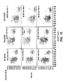
- Figs. 13 through 16 graphically present the results of critical density experiments.
- Fig. 13 is a graphical presentation of velocity versus density relationship at a 40 l/min flow rate.
- Figure 14 is a graphical presentation of velocity versus density relationship at 60 l/min flow rate.
- Figure 15 is a graphical presentation of velocity versus density relationship at 80 l/min flow rate.
- Figure 16 is a graphical presentation of the critical density range determined from 27 experimental runs.
- Critical density is therefore defined as the particle density value or density range with the highest likelihood of containing the fastest particle.
- the target density is defined as the arithmetic mean of the critical density range and can then be used as a basis for density compensation of simulated particles to be used for the residence time measurement so that the residence time measurement will be conservative.
- the particle is ready for insertion into the flow of food to be characterized.
- the detectable particles are inserted into a food product flowing through a thermal system at pre-selected intervals.
- the insertion delay intervals are selected to maximize the number of inserted detectable particles per unit time and minimize the time and quantity of food product used for the required measurements.
- an insertion device can be used if desired, no special insertion device is needed.
- the first detectable particle can be simply inserted into a hopper that is in communication with the stream of food and the timing delay for the remaining particles, as presented in the Tables 2b through 2f below, can be started at the time of system entry detection.
- An insertion device with controlled delay or feedback trigger that is calibrated to activate according to the interval delays described in Tables 2b through 2f below can also be used to control the insertion timing. Such a device is placed in communication with a continuous flow to accomplish insertion.
- the injection delay intervals are selected based on several assumptions:
- the calculation of the minimum insertion delay allows the insertion of the following particle before the previous particle has cleared the system by insuring that the delay is sufficient to avoid the meeting of identical i.d. particles.
- particle having magnetic i.d.s 2, 3, 4, etc. can be inserted into the flow one after another during the pre-selected interval before the next particle having magnetic i.d. 1 is inserted.
- the method and system of this invention provide for the presence of a plurality of detectable particles in the stream at one time.
- Tables 2a through 2f present calculations of minimum required delay time between successive particle injections for a range of operating conditions. All calculations are based on a 2 in. (5.08 cm) internal diameter hold tube.
- Table 2a demonstrates the product usage and time needed to perform the residence time measurements by the standard methodology.
- Table 2b illustrates the principle of calculated time delay interval using a single type of magnetic implant identification, establishing a required time delay needed to avoid the contact of two subsequent particles with the same magnetic identification.
- Tables 2c, 2d, 2e and 2f illustrate the advantages (savings in time and product) when multiple (2, 3, 4, and 5 respectively) magnetic i.d.s are used for particle tagging.
- the insertion delay interval is thus divided by 2, 3, 4 and 5 respectively while maintaining the same minimum insertion delay between two particles having the same magnetic i.d.s.
- Tables 2a through 2f describe three sets of runs at flow rates of 40, 60 and 80 liters per minute and in tubes of 40, 60 and 80 meters in length. Thus, each table includes nine (9) entries. Due to margin requirements and character size considerations, the tables have been assembled in segments below. Each line of data within each table begins with, or falls below, a number between 1 and 9 to correspond with each run. Thus, the table segments should be reviewed with this numbering system in mind.
- Table 2a PRODUCT USAGE AND TIME FOR PRIOR ART METHODS Flow rates Avg. fluid velocity Tube Avg. time of flight [l/min] [m 3 /s] [m/s] [m] [s] 1. 40 0.000667 0.32892 40 121.61 2.
- Detection and identification of particles 10 can be accomplished by using a variety of magnetic sensors.
- a copper coil sensor is one suitable example. Copper coil sensors have medium sensitivity and are based on magnetic flux change. A minimum particle velocity is required for detection.
- Hall effect sensors are also acceptable, as the sensors are medium/high sensitivity and can detect changes in magnetic flux under temperature conditions up to 110°C.
- the preferred magnetic sensor relies on the giant magneto-resistive (GMR) phenomenon. This effect is found in metallic thin films comprising magnetic layers a few nanometers thick separated by equally thin non-magnetic layers. A large decrease in the resistance of these films is observed when a magnetic field is applied.
- GMR giant magneto-resistive
- the GMR sensor is very sensitive and can operate at temperatures ranging up to at least 150° C. It is also inexpensive and very small.
- a graph of GMR sensor output characteristics is set forth in Figure 11 . See GMR Sensor Application Notes, available from Nonvolatile Electronics, Incorporated (NVE), 11409 Valley View Road, Eden Prairie, MN 55344-3617 .
- Single or multiple magnetic sensors are located at detection points downstream from the detection location. Time of passage is determined for each tagged particle from the detector response at each location. The outputs from magnetic sensors are used in combination with magnetic implant configuration and insertion delay time to identify each inserted particle within a sequence of single or multiple magnetic identification configurations. Using multiple magnetic identifications, time and product quantity required for the three replicants of 400 particle residence measurement can be reduced by 90% or more.
- the method and system of this invention can be used with a variety of processing configurations and under a variety of process parameter settings. It is particularly appropriate for systems including tube-type heat exchangers (helical heat exchangers, ribbed tube heat exchangers, etc.) but can be used with any existing processing equipment.
- tube-type heat exchangers helical heat exchangers, ribbed tube heat exchangers, etc.
- a segment 32 of pipe suitable for use in a continuous thermal processing apparatus is fitted with a gasket 36 at coupling 38.
- pipe 32 comprises sanitary stainless steel.
- a continuous thermal processing apparatus is described in U.S. Patent No. 5,261,282 , issued to Grabowski et al. on November 16, 1993 .
- Such an apparatus typically includes one or more heating tubes, one or more holding tubes, and one or more cooling tubes, as well as suitable components to package the product after heat treatment. It is contemplated then that pipe 32 can be included as a section within any length of heating, holding or cooling tube.
- Fig. 7 is schematic, it is also contemplated that pipe 32 represents all three sections, heating, holding and cooling, of a standard apparatus.
- Gasket 36 comprises a material suitable for use in a continuous thermal processing apparatus. As described herein, gasket 36 includes sensors 40. A battery 34, or other appropriate DC power source, is operatively connected to sensors 40 to provide appropriate input voltages.
- Gasket 36 is preferably in contact with the flow.
- the sensitivity of detection sensors 40 here GMR sensors, is enhanced by their placement within gasket 36.
- a preferred sensor 40 is available as Part Number AA002-02 (previously Part Number NVS5B15S) from Nonvolatile Electronics, Incorporated (NVE), 11409 Valley View Road, Eden Prairie, MN 55344-3617 .
- NVE Nonvolatile Electronics, Incorporated
- This sensor is capable of detecting a magnetic field at least as low as 0.05 oersteds. Further, this sensor can detect a magnetic field ranging in strength from at least as low as 0.05 oersteds to about 20 oersteds.
- sensors 40 are disposed around the inner periphery of gasket 36, thus placing them proximate to the flow of food without placing an obstruction within the flow. This configuration eliminates the need to sense through the wall of stainless steel pipe 32 (see Fig. 7 ).
- a computer acquisition system 42 including appropriate software is used to monitor and register signals originating at each sensor 40. This output is used for timing and identification on-line and for post process analyses.
- Computer acquisition system 42 preferably comprises a PENTIUM® microprocessor personal computer (PC) including a Keithley Metrobyte DAS1800HC package with TESTPOINT tm software.
- PC PENTIUM® microprocessor personal computer
- TESTPOINT tm software is a commercially available package that can receive sensor signals, process them and output the signals in a suitable form, such as graphically.
- TESTPOINT tm software is designed to be programmable so that the user can customize it according to the user's needs.
- GMR sensors 40a, 40b and 40c are wrapped around pipe 32 using belt 33 at test point locations.
- Belt 33 can be tied on, clipped on, or strapped on using a hook-and-eye type closure sold under the registered trademark VELCRO®.
- Flexible printed circuits which are commercially available, can also be used to mount sensors 40.
- particles 10 are inserted via an insertion means like hopper 30.
- GMR sensors 40a, 40b and 40c are connected to batteries (or other appropriate DC power sources) 44, 46 and 48, respectively, that provide different input voltages so that input voltages that alternate between adjacent sensors are provided.
- GMR sensors 40a, 40b and 40c are also mounted in straps 50 that include flux concentrating material 52 so that alternating sensors pick up different magnetic field strengths.
- the alternating input voltage and/or flux concentrator strengths can be adjusted to magnetic identifications comprising individual magnetic field strengths for particles 10 introduced into a continuous thermal processing system.
- the term "magnetic identifications" also comprises individual magnetic field strengths for particles 10. Signals from the now customized sensors 40a, 40b and 40c are transmitted to computer acquisition system 42 for processing.
- the magnetic I.D. tagging and detection system employs the following components:
- the sensitivity of sensors 40a, 40b and 40c is controlled by two methods (and their combinations):
- Both flux concentrator dimensions and the driving voltages of individual sensor clusters are adjusted so that clear detection and differentiation is achieved between the individual magnetically tagged particle i.d.s.
- NVE Nonvolatile Electronics, Incorporated
- 11409 Valley View Road, Eden Prairie, MN 55344-3617 has established a recommended range of about 0.75 to about 24 volts as input voltages for GMR sensors 40. But, applicants were able to successfully use sensors 40 with voltages ranging from about 1.5 to about 48 volts.
- sensors 40c coded red were fitted with 6 inch flux concentrators 52 and had input voltage of 36 volts from battery 48. Thus, sensors 40c were capable of detecting all inserted magnetically tagged particles 10, including those with the weakest magnetic implants 14.
- sensors 40b with medium sensitivity were fitted with 4 inch flux concentrators 52 and had input voltage of 24 volts from battery 46.
- sensors 40b were capable of detecting all inserted magnetically tagged particles 10 with the exception of those containing the weakest magnetic implants 14.
- the least sensitive sensors 40a (coded blue) were not fitted with flux concentrators 52 and had input voltage of 12 volts from battery 44. Thus, sensors 40a were capable of detecting only those magnetically tagged particles 10 that were tagged with medium and large magnetic implants 14 (0.1 gram and above).
- the TESTPOINT tm software was customized to provide for a color graphical output from the data from the different sensors 40a, 40b and 40c. Thus, particular particles 10 were tracked according to the color-coding described above.
- sensors 40 of the gasket configuration of the system of this invention as described in Figs. 7 and 8 can be customized to detect particular ranges of magnetic identifications in a similar manner as just described.
- FIG. 10 a further alternative configuration for the sensors of the method and system of this invention is depicted.
- the particle 10 including a magnetic implant is detected in a package after the food stream is run through a continuous thermal processing line and packaged.
- the package 54 containing the particle 10 is removed from the line.
- packages 54 are moved along a conveyor belt (not shown in Fig. 10 ).
- Straps 50 including GMR sensors 40 and flux concentrating material 52 are placed proximate to the conveyor belt.
- Batteries 34 are operatively connected to sensors 40.
- Outputs from sensors 40 are directed to computer acquisition system 42.
- Maximum sensitivity sensors 40 are used in this embodiment.
- Particle 10 in a single package 54 is detected, and an appropriate signal reaches computer 42.
- Computer 42 then provides a signal to a user as to which package 54 includes the particle 10 so that it can be removed from the line.
- Tables 3-6 below summarize preferred system dynamics, including injection dynamics. Tables 3-6 also set forth magnetic identification data for the particles in the food flow.
- Table 5 Insertion dynamics: Programmed delay - Max. part. velocity 2 * avg. vel. (Residence time 60.8 s) - Min.
- part. velocity avg. vel. (residence time 121.6 s) Minimum delay 60.8 s - For 400 particles: 6.76 hours; 16,215 L - For 3 replicate runs: 20.27 hours; 48,644 L Table 6 Programmed delay + Magnetic I.D. I.D.s 400 particles 3 runs 1. 6.76 hr; 16,215 L 20.27 hr; 48,644 L 2. 3.38 hr; 8,107 L 10.13 hr; 24,322 L 3. 2.25 hr; 5,405 L 6.76 hr; 16,215 L 4. 1.69 hr; 4,053 L 5.07 hr; 12,161 L 5. 1.35 hr; 3,243 L 4.05 hr; 9,728 L
- Fig. 12 is a graphical presentation of the hour and product amount data information derived from a residence time profile generated from a conventional thermal process (upper bar graph and pie chart on the left side of Fig. 12 ) as compared to the methods of this invention (lower bar graph and pie chart on the right side of Fig. 12 ). These graphs present the dramatic savings in time and product provided by the method and system of this invention.
- the method and system of this invention provides for the use of magnetic tagging implants in combination with other sensing devices implanted in the particle (thermal memory cell, thermal pill, as described in NASA Tech Briefs, June 1990, p.106 ), microbial loaded media or real food products. It additionally provides for the concurrent residence time measurement for the individual solid particle types for multi-phase products containing several different particle components (stews, vegetable mixes, soups, etc.).
- applicants' invention represents a significant advance over all previously available or tested methods in that it ensures reliable detection at all detection points and minimizes the time and product used through the application of calculated insertion delays and multiple particle identification types.
- the simulated particle density is adjusted to the experimentally determined target density rather than an arbitrarily selected value such as initial or final particle density, initial carrier fluid density etc. This adjustment provides an improved level of safety against underprocessing in a variety of processing geometries and configurations.
- No special inserts or viewing ports are necessary for detection and i.d. recognition.
- No special insertion device is needed - a first particle can be simply inserted into a hopper and the timing delay for the remaining particles can be started at the time of system entry detection.
Landscapes
- Physics & Mathematics (AREA)
- General Physics & Mathematics (AREA)
- Fluid Mechanics (AREA)
- Investigating Or Analyzing Materials By The Use Of Magnetic Means (AREA)
- Geophysics And Detection Of Objects (AREA)
Claims (28)
- Verfahren zum Erstellen einer Messung der Verweilzeit eines Partikulat-enthaltenden Lebensmittelprodukts während das Produkt als kontinuierlicher Strom eine Wärmebehandlungsvorrichtung durchläuft, wobei das Verfahren folgende Schritte umfasst:(a) Einführen eines nachweisbaren Partikels (10) an einem Einführungsort (30) in den Strom, wobei das Partikel (10) mit einem magnetischen Implantat (14) markiert ist;(b) Nachweisen des magnetischen Implantats (14) mithilfe eines Magnetsensors (40), der an einem stromabwärts bezogen auf den Einführungsort (30) angeordneten Nachweispunkt (33) angeordnet ist;(c) Bestimmen der Durchlaufzeit des nachweisbaren Partikels (10) in dem Strom unter Verwendung eines Ausgangssignals des Magnetsensors (40); und(d) Erstellen einer Messung der Verweilzeit für den Strom unter Verwendung der Durchlaufzeit des nachweisbaren Partikels (10);gekennzeichnet durch:bei Schritt (a) Einführen einer Vielzahl der nachweisbaren Partikel (10) in den Strom an dem Einführungsort (30) in vorausgewählten Intervallen, einschließlich wenigstens eines ersten Partikels und eines zweiten Partikels, die beide ein magnetisches Implantat (14) mit der gleichen magnetischen Identifizierung aufweisen, wobei das erste und das zweite Partikel um eine Mindest-Einführungsverzögerung getrennt sind, wobei die Mindest-Einführungsverzögerung so berechnet ist, dass das zweite Partikel eingeführt wird, bevor das erste Partikel den Nachweispunkt (33) erreicht hat, während vermieden wird, dass das zweite Partikel das erste Partikel einholt, bevor das erste Partikel den Nachweispunkt (33) erreicht.
- Verfahren gemäß Anspruch 1, wobei der Sensor (40) eine derartige Empfindlichkeit aufweist, dass der Sensor fähig ist, ein Magnetfeld nachzuweisen, das in einem Bereich von wenigstens 0,05 Oersted niedrig bis etwa 20 Oersted liegt.
- Verfahren gemäß Anspruch 1, ferner umfassend das Bereitstellen wenigstens eines nachweisbaren Partikels (10), wobei wenigstens ein physikalischer Parameter des nachweisbaren Partikels (10), der das Verhalten des Partikels (10) in dem Strom beeinflusst, eingestellt wird, um eine konservative Verweilzeitmessung zu erhalten.
- Verfahren gemäß Anspruch 3, wobei der physikalische Parameter aus der Gruppe bestehend aus Dichte, Größe, Form und Kombinationen davon ausgewählt ist.
- Verfahren gemäß Anspruch 4, wobei die Dichte des nachweisbaren Partikels (10) auf eine vorbestimmte Zieldichte eingestellt wird.
- Verfahren gemäß Anspruch 5, wobei die Zieldichte die Dichte mit der höchsten Wahrscheinlichkeit des Umfassens eines schnellsten Partikels ist.
- Verfahren gemäß Anspruch 1, wobei die magnetischen Implantate (14) ein Material ausgewählt aus der Gruppe bestehend aus Neodym-Eisen-Bor, Kobalt-Seltenerd, Aluminium-Nickel, Keramik, organischem Stoff, Kunststoff-eingebettetem/eingebetteter Metall oder Keramik und Kombinationen davon umfassen.
- Verfahren gemäß Anspruch 1, wobei das vorausgewählte Intervall eine Zeitspanne umfasst, die kleiner als die Zeitspanne ist, die erforderlich ist, um ein erstes nachweisbares Partikel (10) eine vorbestimmte Länge der Wärmebehandlungsvorrichtung durchlaufen zu lassen.
- Verfahren gemäß Anspruch 1, ferner umfassend das Platzieren eines oder mehrerer zusätzlicher Magnetsensoren (40a, 40b, 40c) an dem Nachweispunkt (33); und Bestimmen der Durchlaufzeit der nachweisbaren Partikel (10) in dem Strom unter Verwendung eines Ausgangssignals jedes Sensors (40a, 40b, 40c).
- Verfahren gemäß Anspruch 1, ferner umfassend das Platzieren des Magnetsensors (40) nahe dem Strom unter Verwendung eines Dichtungselements (36).
- Verfahren gemäß Anspruch 1, ferner umfassend das Platzieren zusätzlicher Magnetsensoren (40a, 40b, 40c) an einem oder mehreren zusätzlichen Nachweispunkten stromabwärts bezogen auf den Einführungsort (30); und Bestimmen der Durchlaufzeit der nachweisbaren Partikel (10) in dem Strom unter Verwendung eines Ausgangssignals jedes der Magnetsensoren (40a, 40b, 40c).
- Verfahren gemäß Anspruch 11, ferner umfassend das Platzieren zusätzlicher Magnetsensoren (40a, 40b, 40c) an einer Vielzahl von zusätzlichen Nachweispunkten stromabwärts bezogen auf den Einführungsort (30); und Bestimmen der Durchlaufzeit der nachweisbaren Partikel (10) in dem Strom unter Verwendung eines Ausgangssignals jedes der Magnetsensoren (40).
- System zum Erstellen einer Messung der Verweilzeit eines Partikulat-enthaltenden Lebensmittelprodukts während das Produkt als kontinuierlicher Strom eine Wärmebehandlungsvorrichtung durchläuft, wobei das System umfasst:ein mit einem magnetischen Implantat (14) markiertes nachweisbares Partikel (10);Mittel zum Einführen des nachweisbaren Partikels (10) an einem Einführungsort (30) in den Produktstrom;Mittel zum Nachweisen des magnetischen Implantats (14) in dem nachweisbaren Partikel (10) an einem Nachweispunkt (33) stromabwärts bezogen auf den Einführungsort (30), wobei das Mittel zum Nachweisen wenigstens einen Magnetsensor (40) aufweist;Mittel zum Bestimmen der Durchlaufzeit des nachweisbaren Partikels (10) in dem Strom unter Verwendung eines Ausgangssignals des Magnetsensors (40); undMittel zum Erstellen einer Messung der Verweilzeit für den Strom unter Verwendung der Durchlaufzeit des nachweisbaren Partikels (10);dadurch gekennzeichnet, dass:das Mittel zum Einführen (30) dafür gestaltet ist, eine Vielzahl der nachweisbaren Partikel (10) in vorausgewählten Intervallen an dem Einführungsort (30) in den Strom einzuführen, einschließlich wenigstens eines ersten Partikels und eines zweiten Partikels, die beide ein magnetisches Implantat (14) mit der gleichen magnetischen Identifizierung aufweisen und um eine Mindest-Einführungsverzögerung getrennt sind, wobei die Mindest-Einführungsverzögerung so berechnet ist, dass das zweite Partikel eingeführt wird, bevor das erste Partikel den Nachweispunkt (33) erreicht hat, während vermieden wird, dass das zweite Partikel das erste Partikel einholt, bevor das erste Partikel den Nachweispunkt (33) erreicht.
- System gemäß Anspruch 13, wobei die Vielzahl von nachweisbaren Partikeln (10) Partikel (10) mit verschiedenen magnetischen Identifikationen umfasst, die durch Einschließen eines verschiedenen magnetischen Implantats (14) in jedes Partikel (10) erzeugt sind.
- System gemäß Anspruch 14, wobei die verschiedenen magnetischen Implantate (14) in einem physikalischen Parameter variieren, der ausgewählt ist aus der Gruppe bestehend aus der Anzahl der Implantate (14) in dem Partikel (10), der Größe des Implantats (14), der Form des Implantats (14), der Masse des Implantats (14), dem verwendeten magnetischen Material, dem Ort des Implantats (14) innerhalb des Partikels (10) und Kombinationen davon.
- System gemäß Anspruch 13, wobei der Magnetsensor (40) eine derartige Empfindlichkeit aufweist, dass der Magnetsensor (40) fähig ist, ein Magnetfeld nachzuweisen, das in einem Bereich von wenigstens 0,05 Oersted niedrig bis etwa 20 Oersted liegt.
- System gemäß Anspruch 13, wobei wenigstens ein physikalischer Parameter des wenigstens einen nachweisbaren Partikels (10) in dem Strom eingestellt wird, um eine konservative Verweilzeitmessung zu erhalten.
- System gemäß Anspruch 17, wobei der physikalische Parameter aus der Gruppe bestehend aus Dichte, Größe, Form und Kombinationen davon ausgewählt ist.
- System gemäß Anspruch 18, wobei die Dichte des Partikels (10) auf eine vorbestimmte Zieldichte eingestellt wird.
- System gemäß Anspruch 19, wobei die Zieldichte die Dichte mit der höchsten Wahrscheinlichkeit des Umfassens eines schnellsten Partikels ist.
- System gemäß Anspruch 13, wobei die magnetischen Implantate (14) ein Material ausgewählt aus der Gruppe bestehend aus Neodym-Eisen-Bor, Kobalt-Seltenerd, Aluminium-Nickel, Keramik, organischem Stoff, Kunststoff-eingebettetem/eingebetteter Metall oder Keramik und Kombinationen davon umfassen.
- System gemäß Anspruch 13, wobei das Mittel zum Nachweisen der magnetischen Implantate (14) ferner ein Dichtungselement (36) umfasst, wobei der wenigstens eine Magnetsensor (40) in dem Dichtungselement (36) befestigt ist.
- System gemäß Anspruch 13, wobei das Mittel zum Nachweisen der magnetischen Implantate (14) ferner eine Vielzahl von Sensoren (40a, 40b, 40c) umfasst.
- System gemäß Anspruch 23, wobei das Mittel zum Nachweisen der magnetischen Implantate (14) ferner ein Dichtungselement (36) umfasst, wobei die Vielzahl von Sensoren (40a, 40b, 40c) in dem Dichtungselement (36) befestigt ist.
- System gemäß Anspruch 23, wobei jeder der Sensoren (40a, 40b, 40c) dem Magnetfeld jedes der nachweisbaren Partikel (10) entsprechend kalibriert ist, so dass jeder Sensor (40a, 40b, 40c) einen verschiedenen Bereich der Partikel (10) nachweist.
- System gemäß Anspruch 13, ferner umfassend ein zusätzliches Mittel zum Nachweisen der magnetischen Implantate (14), die an einem oder mehreren zusätzlichen Nachweispunkten stromabwärts bezogen auf den Einführungsort (30) der nachweisbaren Partikel (10) lokalisierbar sind.
- System gemäß Anspruch 26, ferner umfassend zusätzliche Mittel zum Nachweisen der magnetischen Implantate (14), die an einer Vielzahl von zusätzlichen Nachweispunkten stromabwärts bezogen auf den Einführungsort (30) lokalisierbar sind.
- System gemäß Anspruch 13, ferner umfassend Mittel (42) zum graphischen Anzeigen eines Ausgangssignals des wenigstens einen Sensors (40).
Applications Claiming Priority (3)
| Application Number | Priority Date | Filing Date | Title |
|---|---|---|---|
| US946277 | 1997-10-07 | ||
| US08/946,277 US5932813A (en) | 1997-10-07 | 1997-10-07 | Method and system for residence time measurement of simulated food particles in continuous thermal food processing and simulated food particles for use in same |
| PCT/US1998/015521 WO1999018416A1 (en) | 1997-10-07 | 1998-07-28 | Thermal processor measurement using simulated food particles |
Publications (3)
| Publication Number | Publication Date |
|---|---|
| EP1019680A1 EP1019680A1 (de) | 2000-07-19 |
| EP1019680A4 EP1019680A4 (de) | 2000-11-22 |
| EP1019680B1 true EP1019680B1 (de) | 2016-03-23 |
Family
ID=25484247
Family Applications (1)
| Application Number | Title | Priority Date | Filing Date |
|---|---|---|---|
| EP98937153.9A Expired - Lifetime EP1019680B1 (de) | 1997-10-07 | 1998-07-28 | Thermische messung mit simulierten nahrungspartikeln |
Country Status (5)
| Country | Link |
|---|---|
| US (4) | US5932813A (de) |
| EP (1) | EP1019680B1 (de) |
| AU (1) | AU749423B2 (de) |
| CA (1) | CA2305738C (de) |
| WO (1) | WO1999018416A1 (de) |
Families Citing this family (26)
| Publication number | Priority date | Publication date | Assignee | Title |
|---|---|---|---|---|
| FR2761455B1 (fr) * | 1997-03-28 | 1999-05-14 | Bio Merieux | Procede et dispositif pour le controle de flux liquides dans des reseaux de canalisations |
| AU2006200767B2 (en) * | 1997-10-07 | 2008-04-24 | North Carolina State University | Thermal processor measurement using simulated food particles |
| US6743639B1 (en) | 1999-10-13 | 2004-06-01 | Nve Corporation | Magnetizable bead detector |
| US6875621B2 (en) | 1999-10-13 | 2005-04-05 | Nve Corporation | Magnetizable bead detector |
| US6776523B2 (en) | 2000-03-10 | 2004-08-17 | North Carolina State University | Method and system for conservative evaluation, validation and monitoring of thermal processing |
| US6736978B1 (en) | 2000-12-13 | 2004-05-18 | Iowa State University Research Foundation, Inc. | Method and apparatus for magnetoresistive monitoring of analytes in flow streams |
| EP1296276A1 (de) * | 2001-09-21 | 2003-03-26 | EM Microelectronic-Marin SA | Verfahren zur Steuerung des Empfängers eines Transponders für grosse Entfernungen |
| US8590537B2 (en) * | 2002-09-06 | 2013-11-26 | Koninklijke Philips N.V. | Devices, systems and methods using magnetic force systems in the tongue |
| CA2513607C (en) * | 2003-01-28 | 2016-12-13 | North Carolina State University | Methods, systems, and devices for evaluation of thermal treatment |
| US7060992B1 (en) | 2003-03-10 | 2006-06-13 | Tiax Llc | System and method for bioaerosol discrimination by time-resolved fluorescence |
| US20060237665A1 (en) * | 2003-03-10 | 2006-10-26 | Barney William S | Bioaerosol discrimination |
| ATE387107T1 (de) * | 2003-07-30 | 2008-03-15 | Fmc Technologies | Aseptisches behandlungssystem und -verfahren |
| US7211287B2 (en) * | 2004-06-24 | 2007-05-01 | Cargill, Incorporated | Egg Products |
| US7391091B2 (en) | 2004-09-29 | 2008-06-24 | Nve Corporation | Magnetic particle flow detector |
| US20090278875A1 (en) * | 2005-11-14 | 2009-11-12 | Mydata Automation Ab | Jetting Apparatus and Method of Improving the Performance of a Jetting Apparatus |
| US20080319247A1 (en) * | 2007-06-21 | 2008-12-25 | Philadelphia Health & Education Corporation D/B/A Drexel University College Of Medicine | Method of local therapy using magnetizable thermoplastic implant |
| ES2534243T3 (es) | 2008-09-23 | 2015-04-20 | Aseptia, Inc. | Sistema electromagnético |
| DE102010023129A1 (de) * | 2010-06-09 | 2011-12-15 | Basf Se | Verfahren und Vorrichtung zur Bestimmung der Strömungsgeschwindigkeit magnetischer oder ferromagnetischer Partikel und deren Verwendung |
| DE102010040717A1 (de) * | 2010-09-14 | 2012-04-19 | Basf Se | Verfahren und Vorrichtung zur Bestimmung der Strömungsgeschwindigkeit mittels ausgerichteten magnetischen Partikeln und deren Verwendung |
| US8293018B2 (en) | 2010-10-22 | 2012-10-23 | Bepex International, Llc | System and method for the continuous treatment of solids at non-atmospheric pressure |
| EP2697660B1 (de) | 2011-04-15 | 2019-03-20 | Indiana University of Pennsylvania | Wärmeaktivierte magnet- und widerstandshärtung |
| US9157879B2 (en) | 2011-04-15 | 2015-10-13 | Indiana University of Pennsylvania | Thermally activated magnetic and resistive aging |
| US9366580B2 (en) * | 2012-12-21 | 2016-06-14 | John Bean Technologies Corporation | Thermal measurement and process control |
| US20160153022A1 (en) * | 2014-12-02 | 2016-06-02 | Aseptia, Inc. | Individually traceable multi-functional carrier particles for validation of continuous flow thermal processing of particle-containing foods and biomaterials |
| WO2016090014A1 (en) * | 2014-12-02 | 2016-06-09 | Aseptia, Inc. | Method for design and control of properties of simulated food particles for process monitoring and validation of aseptically processed multiphase foods and biomaterials |
| ES2953757B2 (es) * | 2022-04-01 | 2024-11-04 | Gemina I Mas D S L | Metodo de reduccion y/o eliminacion de agente objetivo |
Family Cites Families (28)
| Publication number | Priority date | Publication date | Assignee | Title |
|---|---|---|---|---|
| US2631242A (en) * | 1953-03-10 | Demarcation of fluids in pipe lines | ||
| US3406569A (en) * | 1965-07-07 | 1968-10-22 | Fischer & Porter Co | Magnetic flowmeter of improved linearity |
| US3605741A (en) * | 1969-06-09 | 1971-09-20 | Jordan L Spencer | Intravenous flow control system |
| FR2155057A5 (de) * | 1971-10-05 | 1973-05-18 | Inac | |
| US3965741A (en) * | 1975-05-08 | 1976-06-29 | Campbell Soup Company | Time temperature indicator device and method |
| US4215342A (en) * | 1978-03-31 | 1980-07-29 | Intex Inc. | Merchandise tagging technique |
| US4541719A (en) * | 1982-07-20 | 1985-09-17 | Wyatt Philip J | Method and apparatus for characterizing microparticles and measuring their response to their environment |
| CA1223053A (en) * | 1983-10-17 | 1987-06-16 | Her Majesty The Queen In Right Of Canada As Represented By The Minister Of National Defence Of Her Majesty's Canadian Government | Ferromagnetic wear detector |
| CA1261170A (en) * | 1985-10-11 | 1989-09-26 | Her Majesty The Queen In Right Of Canada As Represented By The Minister Of National Defence Of Her Majesty's Canadian Government | Ferromagnetic wear detector and method |
| NL8802714A (nl) * | 1987-11-24 | 1989-06-16 | Stork Amsterdam | Werkwijze voor het in continue doorstroming thermisch behandelen van een produktmengsel bestaande uit een vloeistof met daarin opgenomen vaste delen. |
| JPH02161360A (ja) * | 1988-06-06 | 1990-06-21 | Daido Metal Co Ltd | 検流器 |
| FR2639689B1 (fr) * | 1988-11-29 | 1991-01-11 | Roulements Soc Nouvelle | Roulement a capteur d'informations |
| US5159564A (en) * | 1988-12-22 | 1992-10-27 | North Carolina State University | Thermal memory cell and thermal system evaluation |
| US5021981A (en) * | 1988-12-22 | 1991-06-04 | North Carolina State University | Thermal memory cell and thermal system evaluation |
| US5000569A (en) * | 1988-12-28 | 1991-03-19 | Lamb-Weston, Inc. | Light reflection defect detection apparatus and method using pulsed light-emitting semiconductor devices of different wavelengths |
| FR2642122B1 (fr) * | 1989-01-20 | 1991-04-05 | Roulements Soc Nouvelle | Joint d'etancheite tournant a codeur magnetique integre, notamment pour des roulements a capteurs d'informations |
| US5129606A (en) * | 1991-03-07 | 1992-07-14 | Jdr Systems Corporation | Railway wheel sensors |
| US5261282A (en) * | 1992-03-03 | 1993-11-16 | Kraft General Foods, Inc. | Method and apparatus for monitoring a continuous cooking process based on particulate residence time |
| JP2944816B2 (ja) * | 1992-03-23 | 1999-09-06 | 株式会社東芝 | 貯蔵庫の扉開閉検出装置 |
| US5407269A (en) * | 1992-07-09 | 1995-04-18 | International Business Machine Corporation | Dynamic mixing chamber |
| JPH07254510A (ja) * | 1993-08-31 | 1995-10-03 | Yamaha Corp | 磁気抵抗材料 |
| US5741979A (en) * | 1995-11-09 | 1998-04-21 | The United States Of America As Represented By The Administrator Of National Aeronautics And Space Adminstrator | Particle velocity measuring system |
| US5876771A (en) * | 1996-06-20 | 1999-03-02 | Tetra Laval Holdings & Finance, Sa | Process and article for determining the residence time of a food particle |
| US5739437A (en) * | 1996-06-20 | 1998-04-14 | Tetra Laval Holdings & Finance Sa | Process and article for determining the residence time of a food particle TRX-371 |
| US5750907A (en) * | 1996-06-20 | 1998-05-12 | Tetra Laval Holdings & Finance, S.A. | Process and article for determining the residence time of a food particle |
| US5761916A (en) * | 1996-06-21 | 1998-06-09 | Advantage Engineering, Inc. | Display method and apparatus for load and capacity for chillers |
| US5801630A (en) * | 1996-11-08 | 1998-09-01 | Sensormatic Electronics Corporation | Article surveillance magnetic marker having an hysteresis loop with large barkhausen discontinuities at a low field threshold level |
| FR2761455B1 (fr) * | 1997-03-28 | 1999-05-14 | Bio Merieux | Procede et dispositif pour le controle de flux liquides dans des reseaux de canalisations |
-
1997
- 1997-10-07 US US08/946,277 patent/US5932813A/en not_active Expired - Lifetime
-
1998
- 1998-07-28 AU AU85934/98A patent/AU749423B2/en not_active Ceased
- 1998-07-28 CA CA002305738A patent/CA2305738C/en not_active Expired - Lifetime
- 1998-07-28 WO PCT/US1998/015521 patent/WO1999018416A1/en not_active Ceased
- 1998-07-28 EP EP98937153.9A patent/EP1019680B1/de not_active Expired - Lifetime
-
1999
- 1999-04-29 US US09/301,921 patent/US6015231A/en not_active Expired - Lifetime
- 1999-11-19 US US09/443,715 patent/US6536947B1/en not_active Expired - Lifetime
-
2003
- 2003-03-25 US US10/396,912 patent/US6766699B2/en not_active Expired - Lifetime
Also Published As
| Publication number | Publication date |
|---|---|
| CA2305738A1 (en) | 1999-04-15 |
| WO1999018416A1 (en) | 1999-04-15 |
| US5932813A (en) | 1999-08-03 |
| CA2305738C (en) | 2009-10-27 |
| US6536947B1 (en) | 2003-03-25 |
| US6015231A (en) | 2000-01-18 |
| AU8593498A (en) | 1999-04-27 |
| US20030177842A1 (en) | 2003-09-25 |
| AU749423B2 (en) | 2002-06-27 |
| EP1019680A4 (de) | 2000-11-22 |
| US6766699B2 (en) | 2004-07-27 |
| EP1019680A1 (de) | 2000-07-19 |
Similar Documents
| Publication | Publication Date | Title |
|---|---|---|
| EP1019680B1 (de) | Thermische messung mit simulierten nahrungspartikeln | |
| US7004620B2 (en) | Method and system for conservative evaluation, validation and monitoring of thermal processing | |
| AU2001247375A1 (en) | Method and system for conservative evaluation, validation and monitoring of thermal processing | |
| AU718696B2 (en) | Local magnetic temperature measurement for aseptic processing | |
| KR20180021802A (ko) | 금속 검지용 센서 및 해당 센서를 사용한 금속 검지 방법 | |
| EP1623048B1 (de) | Verfahren, systeme und vorrichtungen zur beurteilung einer wärmebehandlung | |
| Singh et al. | Heat transfer phenomena during thermal processing of liquid particulate mixtures—A review | |
| US5261282A (en) | Method and apparatus for monitoring a continuous cooking process based on particulate residence time | |
| EP2400282A2 (de) | Verfahren und Steuerung von Verfahrensparametern | |
| AU2006200767B2 (en) | Thermal processor measurement using simulated food particles | |
| AU2002301264B2 (en) | Thermal processor measurement using simulated food particles | |
| MXPA00003464A (en) | Thermal processor measurement using simulated food particles | |
| Coronel et al. | Aseptic processing of particulate foods | |
| Simunovic | Particle flow monitoring in multiphase aseptic systems |
Legal Events
| Date | Code | Title | Description |
|---|---|---|---|
| PUAI | Public reference made under article 153(3) epc to a published international application that has entered the european phase |
Free format text: ORIGINAL CODE: 0009012 |
|
| 17P | Request for examination filed |
Effective date: 20000330 |
|
| AK | Designated contracting states |
Kind code of ref document: A1 Designated state(s): AT BE CH CY DE DK ES FI FR GB GR IE IT LI LU MC NL PT SE |
|
| AX | Request for extension of the european patent |
Free format text: AL PAYMENT 20000330;LV PAYMENT 20000330;MK PAYMENT 20000330;RO PAYMENT 20000330;SI PAYMENT 20000330 |
|
| RIN1 | Information on inventor provided before grant (corrected) |
Inventor name: SIMUNOVIC, JOSIP Inventor name: SWARTZEL, KENNETH, R. |
|
| A4 | Supplementary search report drawn up and despatched |
Effective date: 20001010 |
|
| AK | Designated contracting states |
Kind code of ref document: A4 Designated state(s): AT BE CH CY DE DK ES FI FR GB GR IE IT LI LU MC NL PT SE |
|
| 17Q | First examination report despatched |
Effective date: 20070410 |
|
| GRAP | Despatch of communication of intention to grant a patent |
Free format text: ORIGINAL CODE: EPIDOSNIGR1 |
|
| INTG | Intention to grant announced |
Effective date: 20151001 |
|
| GRAS | Grant fee paid |
Free format text: ORIGINAL CODE: EPIDOSNIGR3 |
|
| GRAA | (expected) grant |
Free format text: ORIGINAL CODE: 0009210 |
|
| AK | Designated contracting states |
Kind code of ref document: B1 Designated state(s): AT BE CH CY DE DK ES FI FR GB GR IE IT LI LU MC NL PT SE |
|
| AX | Request for extension of the european patent |
Extension state: AL LV MK RO SI |
|
| REG | Reference to a national code |
Ref country code: GB Ref legal event code: FG4D |
|
| REG | Reference to a national code |
Ref country code: CH Ref legal event code: EP |
|
| REG | Reference to a national code |
Ref country code: AT Ref legal event code: REF Ref document number: 783616 Country of ref document: AT Kind code of ref document: T Effective date: 20160415 |
|
| REG | Reference to a national code |
Ref country code: IE Ref legal event code: FG4D |
|
| REG | Reference to a national code |
Ref country code: DE Ref legal event code: R096 Ref document number: 69843512 Country of ref document: DE |
|
| REG | Reference to a national code |
Ref country code: SE Ref legal event code: TRGR |
|
| REG | Reference to a national code |
Ref country code: NL Ref legal event code: MP Effective date: 20160323 |
|
| PG25 | Lapsed in a contracting state [announced via postgrant information from national office to epo] |
Ref country code: FI Free format text: LAPSE BECAUSE OF FAILURE TO SUBMIT A TRANSLATION OF THE DESCRIPTION OR TO PAY THE FEE WITHIN THE PRESCRIBED TIME-LIMIT Effective date: 20160323 Ref country code: GR Free format text: LAPSE BECAUSE OF FAILURE TO SUBMIT A TRANSLATION OF THE DESCRIPTION OR TO PAY THE FEE WITHIN THE PRESCRIBED TIME-LIMIT Effective date: 20160624 |
|
| REG | Reference to a national code |
Ref country code: AT Ref legal event code: MK05 Ref document number: 783616 Country of ref document: AT Kind code of ref document: T Effective date: 20160323 |
|
| PG25 | Lapsed in a contracting state [announced via postgrant information from national office to epo] |
Ref country code: NL Free format text: LAPSE BECAUSE OF FAILURE TO SUBMIT A TRANSLATION OF THE DESCRIPTION OR TO PAY THE FEE WITHIN THE PRESCRIBED TIME-LIMIT Effective date: 20160323 |
|
| PG25 | Lapsed in a contracting state [announced via postgrant information from national office to epo] |
Ref country code: AT Free format text: LAPSE BECAUSE OF FAILURE TO SUBMIT A TRANSLATION OF THE DESCRIPTION OR TO PAY THE FEE WITHIN THE PRESCRIBED TIME-LIMIT Effective date: 20160323 Ref country code: PT Free format text: LAPSE BECAUSE OF FAILURE TO SUBMIT A TRANSLATION OF THE DESCRIPTION OR TO PAY THE FEE WITHIN THE PRESCRIBED TIME-LIMIT Effective date: 20160725 Ref country code: ES Free format text: LAPSE BECAUSE OF FAILURE TO SUBMIT A TRANSLATION OF THE DESCRIPTION OR TO PAY THE FEE WITHIN THE PRESCRIBED TIME-LIMIT Effective date: 20160323 |
|
| PGFP | Annual fee paid to national office [announced via postgrant information from national office to epo] |
Ref country code: SE Payment date: 20160720 Year of fee payment: 19 |
|
| PG25 | Lapsed in a contracting state [announced via postgrant information from national office to epo] |
Ref country code: BE Free format text: LAPSE BECAUSE OF FAILURE TO SUBMIT A TRANSLATION OF THE DESCRIPTION OR TO PAY THE FEE WITHIN THE PRESCRIBED TIME-LIMIT Effective date: 20160323 Ref country code: IT Free format text: LAPSE BECAUSE OF FAILURE TO SUBMIT A TRANSLATION OF THE DESCRIPTION OR TO PAY THE FEE WITHIN THE PRESCRIBED TIME-LIMIT Effective date: 20160323 |
|
| REG | Reference to a national code |
Ref country code: DE Ref legal event code: R097 Ref document number: 69843512 Country of ref document: DE |
|
| PLBE | No opposition filed within time limit |
Free format text: ORIGINAL CODE: 0009261 |
|
| STAA | Information on the status of an ep patent application or granted ep patent |
Free format text: STATUS: NO OPPOSITION FILED WITHIN TIME LIMIT |
|
| PG25 | Lapsed in a contracting state [announced via postgrant information from national office to epo] |
Ref country code: DK Free format text: LAPSE BECAUSE OF FAILURE TO SUBMIT A TRANSLATION OF THE DESCRIPTION OR TO PAY THE FEE WITHIN THE PRESCRIBED TIME-LIMIT Effective date: 20160323 |
|
| REG | Reference to a national code |
Ref country code: DE Ref legal event code: R119 Ref document number: 69843512 Country of ref document: DE |
|
| REG | Reference to a national code |
Ref country code: CH Ref legal event code: PL |
|
| 26N | No opposition filed |
Effective date: 20170102 |
|
| GBPC | Gb: european patent ceased through non-payment of renewal fee |
Effective date: 20160728 |
|
| PG25 | Lapsed in a contracting state [announced via postgrant information from national office to epo] |
Ref country code: MC Free format text: LAPSE BECAUSE OF FAILURE TO SUBMIT A TRANSLATION OF THE DESCRIPTION OR TO PAY THE FEE WITHIN THE PRESCRIBED TIME-LIMIT Effective date: 20160323 |
|
| PG25 | Lapsed in a contracting state [announced via postgrant information from national office to epo] |
Ref country code: FR Free format text: LAPSE BECAUSE OF NON-PAYMENT OF DUE FEES Effective date: 20160801 Ref country code: DE Free format text: LAPSE BECAUSE OF NON-PAYMENT OF DUE FEES Effective date: 20170201 Ref country code: LI Free format text: LAPSE BECAUSE OF NON-PAYMENT OF DUE FEES Effective date: 20160731 Ref country code: CH Free format text: LAPSE BECAUSE OF NON-PAYMENT OF DUE FEES Effective date: 20160731 |
|
| REG | Reference to a national code |
Ref country code: FR Ref legal event code: ST Effective date: 20170331 |
|
| REG | Reference to a national code |
Ref country code: IE Ref legal event code: MM4A |
|
| PG25 | Lapsed in a contracting state [announced via postgrant information from national office to epo] |
Ref country code: GB Free format text: LAPSE BECAUSE OF NON-PAYMENT OF DUE FEES Effective date: 20160728 |
|
| PG25 | Lapsed in a contracting state [announced via postgrant information from national office to epo] |
Ref country code: IE Free format text: LAPSE BECAUSE OF NON-PAYMENT OF DUE FEES Effective date: 20160728 |
|
| PG25 | Lapsed in a contracting state [announced via postgrant information from national office to epo] |
Ref country code: LU Free format text: LAPSE BECAUSE OF NON-PAYMENT OF DUE FEES Effective date: 20160728 |
|
| REG | Reference to a national code |
Ref country code: SE Ref legal event code: EUG |
|
| PG25 | Lapsed in a contracting state [announced via postgrant information from national office to epo] |
Ref country code: SE Free format text: LAPSE BECAUSE OF NON-PAYMENT OF DUE FEES Effective date: 20170729 |
|
| PG25 | Lapsed in a contracting state [announced via postgrant information from national office to epo] |
Ref country code: CY Free format text: LAPSE BECAUSE OF FAILURE TO SUBMIT A TRANSLATION OF THE DESCRIPTION OR TO PAY THE FEE WITHIN THE PRESCRIBED TIME-LIMIT Effective date: 20160323 |