EP1019668B1 - Speckle methods and apparatus for determining angular displacement, surface translation, and twist - Google Patents
Speckle methods and apparatus for determining angular displacement, surface translation, and twist Download PDFInfo
- Publication number
- EP1019668B1 EP1019668B1 EP98921364A EP98921364A EP1019668B1 EP 1019668 B1 EP1019668 B1 EP 1019668B1 EP 98921364 A EP98921364 A EP 98921364A EP 98921364 A EP98921364 A EP 98921364A EP 1019668 B1 EP1019668 B1 EP 1019668B1
- Authority
- EP
- European Patent Office
- Prior art keywords
- fourier
- parts
- speckles
- image sensor
- electromagnetic radiation
- Prior art date
- Legal status (The legal status is an assumption and is not a legal conclusion. Google has not performed a legal analysis and makes no representation as to the accuracy of the status listed.)
- Expired - Lifetime
Links
- 238000006073 displacement reaction Methods 0.000 title claims description 161
- 238000000034 method Methods 0.000 title claims description 52
- 238000013519 translation Methods 0.000 title claims description 15
- 230000005670 electromagnetic radiation Effects 0.000 claims description 61
- 238000009826 distribution Methods 0.000 claims description 56
- 230000001427 coherent effect Effects 0.000 claims description 25
- 230000003287 optical effect Effects 0.000 claims description 23
- 230000014616 translation Effects 0.000 claims description 14
- 238000001514 detection method Methods 0.000 claims description 12
- 238000003384 imaging method Methods 0.000 claims description 8
- 230000001131 transforming effect Effects 0.000 claims description 4
- 239000004973 liquid crystal related substance Substances 0.000 claims description 2
- 230000003068 static effect Effects 0.000 claims 1
- 238000005259 measurement Methods 0.000 description 12
- XAGFODPZIPBFFR-UHFFFAOYSA-N aluminium Chemical compound [Al] XAGFODPZIPBFFR-UHFFFAOYSA-N 0.000 description 7
- 229910052782 aluminium Inorganic materials 0.000 description 7
- 239000004411 aluminium Substances 0.000 description 7
- 229910000831 Steel Inorganic materials 0.000 description 6
- 239000010959 steel Substances 0.000 description 6
- 101100163901 Rattus norvegicus Asic2 gene Proteins 0.000 description 5
- 230000006870 function Effects 0.000 description 5
- 230000002123 temporal effect Effects 0.000 description 4
- 238000007405 data analysis Methods 0.000 description 3
- 230000001419 dependent effect Effects 0.000 description 3
- 230000001678 irradiating effect Effects 0.000 description 3
- 238000013459 approach Methods 0.000 description 2
- 230000001066 destructive effect Effects 0.000 description 2
- 230000001902 propagating effect Effects 0.000 description 2
- 230000005855 radiation Effects 0.000 description 2
- 230000035945 sensitivity Effects 0.000 description 2
- XUIMIQQOPSSXEZ-UHFFFAOYSA-N Silicon Chemical compound [Si] XUIMIQQOPSSXEZ-UHFFFAOYSA-N 0.000 description 1
- 238000010420 art technique Methods 0.000 description 1
- 230000006399 behavior Effects 0.000 description 1
- 238000005314 correlation function Methods 0.000 description 1
- 230000007423 decrease Effects 0.000 description 1
- 238000005286 illumination Methods 0.000 description 1
- 230000010354 integration Effects 0.000 description 1
- 238000004519 manufacturing process Methods 0.000 description 1
- 238000005488 sandblasting Methods 0.000 description 1
- 229910052710 silicon Inorganic materials 0.000 description 1
- 239000010703 silicon Substances 0.000 description 1
- 239000007787 solid Substances 0.000 description 1
- 230000003595 spectral effect Effects 0.000 description 1
- 238000003860 storage Methods 0.000 description 1
- 238000011282 treatment Methods 0.000 description 1
Images




Classifications
-
- G—PHYSICS
- G01—MEASURING; TESTING
- G01L—MEASURING FORCE, STRESS, TORQUE, WORK, MECHANICAL POWER, MECHANICAL EFFICIENCY, OR FLUID PRESSURE
- G01L3/00—Measuring torque, work, mechanical power, or mechanical efficiency, in general
- G01L3/02—Rotary-transmission dynamometers
- G01L3/04—Rotary-transmission dynamometers wherein the torque-transmitting element comprises a torsionally-flexible shaft
- G01L3/10—Rotary-transmission dynamometers wherein the torque-transmitting element comprises a torsionally-flexible shaft involving electric or magnetic means for indicating
- G01L3/12—Rotary-transmission dynamometers wherein the torque-transmitting element comprises a torsionally-flexible shaft involving electric or magnetic means for indicating involving photoelectric means
-
- G—PHYSICS
- G01—MEASURING; TESTING
- G01B—MEASURING LENGTH, THICKNESS OR SIMILAR LINEAR DIMENSIONS; MEASURING ANGLES; MEASURING AREAS; MEASURING IRREGULARITIES OF SURFACES OR CONTOURS
- G01B11/00—Measuring arrangements characterised by the use of optical techniques
- G01B11/16—Measuring arrangements characterised by the use of optical techniques for measuring the deformation in a solid, e.g. optical strain gauge
- G01B11/161—Measuring arrangements characterised by the use of optical techniques for measuring the deformation in a solid, e.g. optical strain gauge by interferometric means
- G01B11/162—Measuring arrangements characterised by the use of optical techniques for measuring the deformation in a solid, e.g. optical strain gauge by interferometric means by speckle- or shearing interferometry
Definitions
- the present invention relates to a method and apparatus for determining angular displacement of one or more parts of an object, said method comprising directing at least one beam of electromagnetic radiation towards one or more parts of the object, detecting speckles from the object surface in at least one first image sensor, and determining one or more speckle displacements before and after the angular displacements of said one or more parts of the object as a function of the angular displacements.
- the invention also relates to a method of determining twist of a rotating shaft subjected to a load; a method of simultaneously determining angular displacements and surface translations of one or more parts of an object; and a method of determining the radius of angular displacement of an object.
- determination of angular displacement of an object using speckle displacement comprises illumination of the surface of the object by a laser beam.
- the reflected laser beam generates a speckle pattern which is detected in a linear image sensor.
- the displaced speckle pattern is detected in the linear image sensor.
- the two speckle patterns are then cross-correlated to determine the angular displacement which is provided by the displacement giving maximum cross-correlation.
- a drawback of this method is that the determination of the angular displacement depends on the distance from the linear sensor to the object, movements of the object, the radius of displacement, as well as the shape of the object.
- Hayashi and Kitagawa "High Resolution Rotation-Angle Measurement of a Cylinder Using Speckle Displacement", Applied Optics, Vol. 22, 1983, p. 3520-3525, disclose a method for measuring the rotation angle of a cylinder, particularly a small rotation angle with high resolution based on the speckle displacement detection in the (near) diffraction field caused by rotation of the cylinder surface.
- the light intensity distributions of speckles before and after the cylinder surface displacement are detected by a detector array, and displacement of the speckle pattern is measured by computing their cross-correlation function.
- Yamaguchi and Fujita disclose a method and apparatus for measuring small rotation angles of a cylinder by detecting displacement of the speckles which appears in the diffraction field of the surface illuminated by a narrow laser beam.
- the speckle pattern is detected by a linear sensor whose output is cross-correlated before and after the rotation of the cylinder. A resolution of 2 millidegrees is reported.
- the angular displacement measurement is dependent of the distance of the linear sensor to the cylinder being measured, longitudinal and transversal movements of the cylinder, its radius, and the shape of the object.
- a method for determining angular displacements of one or more parts of an object comprising
- an apparatus for determining angular displacements of one or more parts of an object comprising:
- the Fourier-transforming means comprises means for providing a Fourier-transformation of the scattered electromagnetic radiation giving rise to linearly displaced speckles due to an angular displacement of the object.
- the Fourier-transforming means comprises means for Fourier-transforming the angle of direction of the speckles generated by the scattered electromagnetic radiation into a linear coordinate of the speckles near or in the Fourier plane.
- the linear coordinates of the Fourier-transformed speckles are the distances of speckles to the optical axis of the Fourier-transforming means, said optical axis being both perpendicular to the Fourier plane and perpendicular to the axis of angular displacement.
- the Fourier-transforming means comprises an optical Fourier-transforming device which Fourier transforms incoming light in the Fourier plane of the device, i.e. in a plane typically coinciding with the focal planes of the Fourier-transforming device.
- Fourier-transforming devices comprise refractive, reflective, and diffractive optical elements, and active liquid crystals, e.g. as disclosed in Goodman, ibid.
- Preferred Fourier-transforming refractive optical elements are selected from refractive lenses whereby simple and readily available optical elements can be used.
- Refractive convex lenses or cylinder lenses are preferred, whereby simple systems can be made with standard components.
- Reflective systems can be designed by using a parabolic mirror and placing the linear image sensor in the focal point.
- Preferred Fourier-transforming diffractive optical elements are selected from diffractive zone plates and holographic lenses, both of which may be computer generated, whereby particularly compact and robust Fourier-transforming means can be provided.
- Holographic lenses are preferred.
- Spherical as well as cylinder lenses can be implemented with diffractive optics.
- the Fourier-transformed speckles provided by surface elements of one or more parts of the object having different positions along the axis of angular displacement are additionally imaged into corresponding positions of the first image sensor, whereby it is obtained that the distribution of angular displacements along one direction of more parts of an object, typically closely spaced surface elements of the irradiated part of the object, can be determined simultaneously.
- the imaging is performed in one direction while maintaining Fourier-transformation in a direction perpendicular thereto.
- the Fourier-transforming device and the imaging means are incorporated in a diffractive optical element, whereby a particular compact and robust embodiment is obtained.
- Methods for incorporating optical elements in diffractive optical elements are known in the art, see e.g. M.T. Gale, "Diffractive Microstructures: Fabrication and Application", Schweizerische Weg für Mikrotechnik (SGMT) Bulletin 17, May 1993.
- the Fourier-transforming means further comprises telescopic means to magnify or reduce the Fourier plane. This is particularly useful for scaling the speckle size to the pixel size of the detector, whereby the maximum resolution can be obtained.
- At least one beam of substantially coherent and substantially parallel electromagnetic radiation is directed towards one or more parts of the object positioned in a first position.
- Suitable electromagnetic irradiation of the object can be provided by methods known in the art.
- More beams of the electromagnetic radiation may be directed towards more parts of the object for simultaneous or subsequent determination of angular displacements of each part.
- the electromagnetic radiations can be generated by the same or different sources.
- a laser source provides a beam of substantially coherent electromagnetic radiation which beam is split up into two beams irradiating two different parts of the object whereby a particular apparatus can be provided.
- the beam of electromagnetic radiation is substantially coherent for the generation of speckles by constructive and destructive interference of the individual components of the electromagnetic radiation scattered by the object.
- the modulation depth of the speckles in the Fourier plane approaches unity, which provides a corresponding high modulation in e.g. the cross-correlation of the detected images of the first and second distributions of the speckles between the first position and the second position of the angularly displaced object.
- the modulation depth of the speckles is low. Consequently, the modulation depth of e.g. the cross-correlation of the detected images decreases, and the pixel position providing maximum cross-correlation is determined with less accuracy and precision.
- Whether the degree of coherence is sufficient for a specific application, e.g. a specific object surface, can be determined by the skilled person according to the methods known in the art, see e.g. J.W. Goodman, "Laser Speckle and Related Phenomena", J.C. Dainty, ed. (Springer-Verlag, Berlin, 1984), Chap. 2.
- the electromagnetic radiation is provided by a laser source, whereby an intensive, parallel beam can be provided. Further, the wavelength can be matched to the spectral sensitivity of the image sensor.
- Suitable laser sources can be selected by a skilled person for a given application, in particular considering coherence and divergence.
- substantially coherent electromagnetic radiation includes incoherent electromagnetic radiation having an induced spatial and temporal coherence. It turns out that the electromagnetic radiation source can be incoherent provided that the spatial coherence length approaches the size of the illuminating spot, and that the temporal coherence length exceeds the depth of the illuminated part of the object.
- the beam of substantially coherent electromagnetic radiation is substantially parallel.
- a non-parallel beam can be accepted, i.e. a diverging or a converging beam.
- the determination of the angular displacement becomes dependent on the distance to the object and on the radius of displacement of the object, even when the image sensor is positioned exactly in the Fourier plane.
- the wavelength of the electromagnetic radiation can be any wavelength suitable of generating speckles in the Fourier plane of the Fourier-transforming means from the electromagnetic radiation scattered from the object surface.
- the sensitivity of the image sensor has to match the wavelength of the electromagnetic radiation.
- the wavelength is a short wavelength, preferably in the range of 0.4 ⁇ m to 1.6 ⁇ m where suitable image sensors are available.
- Preferred source of substantially coherent electromagnetic radiation comprises laser sources, in particular diode lasers, solid state lasers, and gas lasers.
- first and second one or more distributions of speckles provided by at least a part of the electromagnetic radiation scattered from said one or more parts of the object in a first position and in a second position after angular displacement, respectively, are detected in at least one first image sensor.
- angular displacements and surface translation of one or more parts of an object are determined simultaneously.
- a second image sensor is positioned in or near the image plane of the object.
- the first and second image sensors can be equal or different.
- the image sensor consists of one- or two-dimensional array detectors.
- the sensitive area of a single detector, pixel, of the array detector has a size which is comparable with the size of a speckle in or near the Fourier plane, whereby a better resolution is obtained.
- the image sensor is a one-element detector having a short integration time, e.g. a silicon detector, which provides a successively detected image of a timely varying distribution of speckles scattered from a rotating object.
- Preferred embodiments of the first and/or second image sensors comprises array detectors, both one or two one-dimensional array detectors, and two-dimensional array detectors.
- the first and/or second image sensor comprises at least one one-element detector connected to a shift register.
- one or more parts of the object is angularly displaced.
- the angular displacement can be any angular displacement having a corresponding displacement axis.
- the angular displacement is determined in one or two dimensions.
- the distribution of angular displacements of more surface elements of the irradiated one or more parts of the object displacement is determined.
- the relative shift in angular displacements of two or more parts of a rotating object, in particular a rotating shaft, subjected to a load is determined.
- one or more displacements between the first and second distributions of the Fourier-transformed speckles detected in the first image sensor, or the speckles detected in the second image sensor are obtained by cross-correlating the detected images thereof as a function of the angular displacements of said one or more parts of the object between said first and second positions.
- cross-correlation is performed by a method disclosed in M. Sjödahl, "Electronic Speckle Photography: Increased Accuracy by Nonintegral Pixel Shifting", Applied Optics, Vol. 33, 1994, p. 6667-6673, whereby an automatic determination of the pixel position of maximum cross-correlation is achieved.
- the pixel position of maximum cross-correlation provides a measure for the linear displacement of the speckles in the Fourier plane or in the image plane, respectively, i.e. a linear displacement which is proportional to the applied angular displacement, whereby this angular displacement of the object can be determined.
- speckles arise when diffusely scattered electromagnetic radiation, e.g. scattered light from a surface having irregularities smaller than the wavelength of the incident radiation, interferes with each other or with electromagnetic radiation scattered from macrostructures in the surface, e.g. light scattered from irregularities larger than the wavelength of the incident radiation.
- the generated field is either Fourier-transformed into a speckle pattern in the Fourier plane, or the object is imaged into an imaged speckle pattern in the image plane, or both.
- surfaces having a major proportion of diffusely scattered light can be applied.
- the surface may be treated by methods known in the art.
- Preferred treatments of the object surface comprise mounting retroreflective tape, sandblasting the surface, matting the surface.
- a method of determining twist of a rotating object e.g. a shaft, between two or more parts of the rotating object subjected to a load.
- This method is advantageous since it is a non-contact method, independent on distance to the object, any longitudinal or transversal movements of the object, the shape of the object, and the radius of rotation. Further the calibration is independent on the wavelength of the source.
- This method is advantageous since it is a non-contact method.
- This method is advantageous since it is a non-contact method.
- the source of electromagnetic radiation is a laser source.
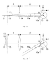
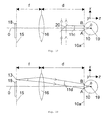
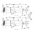
- Fig. 1A shows a cross-sectional sketch of a preferred embodiment for carrying out directing the at least one beam of substantially coherent and substantially parallel electromagnetic radiation towards said one or more parts of the object positioned in a first or in a second position.
- the irradiating beam may be either divergent or parallel irrespectively of the image sensor and the Fourier-transforming means. Further, the irradiating beam can be propagating inside or outside the Fourier-transforming means.
- a slightly divergent beam of light 11a is directed towards a part of a cylinder 10 before and after the cylinder is angularly displaced clockwise between two positions A and B about an axis of displacement 19 perpendicular to the optical axis O.
- the divergent beam 11a is provided by converging a spherical wave 12 of coherent light from a laser point source 13, positioned within the focal distance f 1 of the beam forming lens 14. If the point source is positioned outside the focal distance, the beam will be convergent.
- the light source 13 can be operated either in a pulsed mode or it can be run continuously.
- the beam forming lens 14 is positioned in a distance d 1 to the object plane 10a.
- the distance from the beam forming lens 14 to the object plane 10a can be chosen arbitrarily.
- the beam forming lens 14 collimates the spherical wave 12 into a parallel beam; said point source being placed in the focal point of the lens 14.
- the beam forming lens 14 can be any suitable lens or lens system. It can be chosen by a skilled person depending on the preferred parameters of the beam for a specific application.
- Fig. 1B shows another embodiment of carrying out directing the at least one beam of substantially coherent and substantially parallel beam of electromagnetic radiation 11b (source not shown) towards said one or more parts of the object 10.
- a beam of electromagnetic radiation 11b which can be provided as described in connection with Fig. 1A, is propagating outside of the Fourier-transforming means 16.
- the detector plane 17 of the image sensor 18 is positioned asymmetrically with respect to the optical axis 0 near the Fourier plane 15 of the Fourier-transforming means 16.
- Fig. 1C shows still another embodiment of carrying out directing the at least one beam of substantially coherent and substantially parallel beam of electromagnetic radiation 11c (source not shown) towards said one or more parts of the object 10.
- a semi-transparent mirror 20, or an ordinary mirror directs a substantially parallel and substantially coherent beam of electromagnetic radiation 11c towards said one or more parts of object 10, so that said beam of electromagnetic radiation is centered around the optical axis 0 of the Fourier-transforming means 16.
- the detector plane of the image sensor 18 coincides with the Fourier plane 15 of the Fourier transforming means 16.
- Fig. 1D shows still another embodiment of carrying out directing the at least one beam of substantially coherent and substantially parallel beam of electromagnetic radiation 11d (source not shown) towards said one or more parts of the object 10.
- the source of electromagnetic radiation 13 is placed off-axis to the optical axis O in the Fourier plane 15, i.e. it is placed transversely to the optical axis O, e.g. to provide space for an image sensor 18 having a detector plane which coincide with the Fourier plane 15 of the Fourier-transforming means 16.
- the image sensor 18 is being close to or centered asymmetrically about the optical axis.
- the Fourier-transforming lens 16 is used to provide a substantially parallel and substantially coherent beam of electromagnetic radiation 11d which is directed towards one or more parts of the object 10 inside the aperture of a Fourier transforming means 16.
- the source or electromagnetic radiation 13 can be placed arbitrarily in the Fourier plane 15.
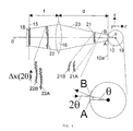
- Fig. 2 shows a cross-sectional sketch of a preferred embodiment for carrying out the detection of said at least a part of the electromagnetic radiation scattered from said one or more parts of the object in said first and second positions.
- a substantially parallel and substantially coherent beam of light (11a 11b, 11c, 11d) irradiates a selected part of the cylinder 10 similar to the beams (11a 11b, 11c, 11d) as shown in Figs. 1A-1D.
- the object is angularly displaced in one dimension only.
- the object 10 is angularly displaced the angle ⁇ with respect to the displacement axis 19.
- An example illustrating angular displacement in two dimensions is provided below.
- FIG. 2 In the blown up part of Fig. 2, there are shown two positions A and B of the object, i.e. the positions before and after the angular displacement of the object, respectively.
- the irradiated part of the object is angularly displaced the angle ⁇ from the position A to the second position B about the displacement axis 19 in a clockwise direction as indicated by the arrow.
- this position B at least a part of the electromagnetic radiation scattered from this part of the object is reflected in a reflection 21B in an angle 2 ⁇ with respect to the reflection 21A in position A.
- Each surface element of the irradiated surface of the object 10 provides a spherically scattered reflection that is diffusely and/or specularly scattered therefrom.
- First and second one or more distributions of speckles are detected in at least one image sensor, i.e. the Fourier-transformed wave patterns before and after angular displacement are detected in said at least one image sensor as distributions of speckles, viz. constructive and destructive interferences of said Fourier-transformed components of the reflection.
- the first 22A and second 22B Fourier-transformed wave patterns provide distributions of speckles before and after the angular displacement of the object, respectively, which are detected in the image sensor; said image sensor being positioned exactly in the Fourier plane 15 of the lens 16. The exact position of the image sensor is not essential as long as it is positioned in or near the Fourier plane.
- the image sensor is a one-dimensional array detector of 512 pixels, RL0512G supplied from EG&G RETICON, USA.
- the reference speckle patterns said first positions are pre-recorded at known fixpoints and stored in a memory array. After the applied angular displacement of the object, the current speckle pattern, said second position, is recorded and the displacement relative to the fixpoints is calculated. This method is in particular advantageous for absolute rotation encoder applications.
- a measure for the size of the section can be obtained from the peak value of the cross-correlation.
- the peak value drops to a value below a given threshold (80 %), the reference signal is replaced by the present one and the speckle displacement is added up.
- Example 1 An illustration of the determination of angular displacement of 0-600 mdeg is shown in Example 1.
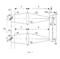
- Fig. 3 shows another cross-sectional sketch of a preferred embodiment for carrying out detecting said first and second one or more distributions of the Fourier-transformed speckles from two far-spaced parts of the object.
- Two substantially parallel and substantially coherent beams of light irradiate the two selected part of the cylinder 10 separated along the longitudinal axis of the object, in analogy to the one part irradiation 11a 11b, 11c, 11d of the object as shown in Figs. 1A-1D.
- the angular displacements of the two parts of the object are determined as illustrated for the embodiment shown in fig. 2.
- the two irradiation and detection configurations can be equal or different.
- the two angular displacements can be used to determine the twist of the object provided the distance between the two parts of the object is known.
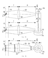
- Figs. 4A and 4B show cross-sectional sketches of a preferred embodiment for carrying out detecting said first and second one or more distributions of Fourier-transformed speckles from more closely spaced parts of the object.
- This example illustrates an embodiment that extends the determination of the two one-dimensional angular displacements of two far spaced parts of an object as shown in Fig. 3 to the determination of more one-dimensional angular displacements of more closely spaced parts of the object.
- the Fourier-transforming means additionally comprises a cylindrical lens 16b inserted between the object 10 and the Fourier-transforming lens 16a in order to perform the necessary imaging along the axis of the shaft.
- the object 10 can be placed arbitrarily, but it is preferably placed in or near the focal plane of the cylindrical lens.
- the cylindrical lens 16b performs imaging in the y-direction whereby surface elements on the irradiated part of the object having different heights are imaged on corresponding heights of the image sensor 18, here a two-dimensional array detector placed in or near the Fourier plane of the Fourier-transforming lens 16a.
- the distance between the cylindrical lens 16b and the Fourier-transforming lens 16a can be chosen arbitrarily.
- the distribution of angular displacements versus y-position of the part of the object irradiated can be determined as the distances between the surface elements of the object, corresponding to the y-lines in the two-dimensional array detector, are known from the geometrical magnification in the y-direction given by methods known in the art, see e.g. A.E. Siegman, "Lasers", University Science Books, USA, 1986.
- Fig. 5 shows a cross-sectional sketch of a preferred embodiment for carrying out the detection of said at least a part of the electromagnetic radiation scattered from said one or more parts of the object in said first and second positions in which the surface translation is additionally determined.
- This embodiment is similar to the embodiment shown in Fig. 2, except that surface translation is additionally detected by a second image sensor 18b placed in or near the image plane 15b of the object 10, and except that the first image sensor 18a detecting the Fourier-transformed speckles is placed in the Fourier plane. If the second image sensor 18b is placed outside the Fourier plane 15a, preferably in or near the image plane 15b positioned 2f from the Fourier-transforming lens 16, then the translation of the surface originating from the angular displacement of the object 10 towards a linear displacement of the distribution of speckles detected therein.
- the radius of angular displacement is determined by methods known in the art.
- the measurements or the surface translation is dependent on the angular displacement (provided by the image sensor placed exactly in the Fourier plane), target distance d the distance from the Fourier lens 16 to the image sensor placed in or near the image plane, and the radius of angular displacement.
- Figs. 6A and 6B show cross-sectional sketches of a preferred embodiment for carrying out detecting said first and second one or more distributions of Fourier-transformed speckles for measuring two-dimensional tilt of an object.
- a substantially parallel and substantially coherent beam of light irradiates a selected part of the plate 10 similar to the beams of light 11a, 11b, 11c, 11d as shown in Figs. 1A-1D.
- the object is angularly displaced in two dimensions; in this example the object 10 is angularly displaced the angle ⁇ with respect to the displacement axis 19a, and angularly displaced the angle ⁇ with respect to the displacement axis 19b.
- This preferred embodiment is similar to the embodiment shown in Fig. 2, except for the image sensor 18 which is a two dimensional array detector of a standard type ccd camera without a lens, e.g. TI-22 CCD camera from NEC, Japan.
- the image sensor 18 which is a two dimensional array detector of a standard type ccd camera without a lens, e.g. TI-22 CCD camera from NEC, Japan.
- the plate 10 is angularly displaced the angle ⁇ in the x-direction, and the angle ⁇ in the y -direction, whereby a surface element moves to position B.
- an angular displacement of ⁇ , ⁇ degrees of the target provides a rotation of 2 ⁇ ,2 ⁇ degrees of the reflection.
- the displacement 2 ⁇ ,2 ⁇ of the reflection is mapped into a linear displacement in the xy-plane on the image sensor 18 placed in or near the Fourier plane.
- the two-dimensional displacement can be determined with the same advantages as those described for the one-dimensional displacement in connection with Fig. 2.
- the two-dimensional array detector provides the advantages of a very compact image sensor compared to the alternative of two one-dimensional array detectors. In particular cases, however, the two-dimensional array detector can be substituted by two one-dimensional array detectors.
- Figs. 7A and 7B show longitudinal and cross-sectional sketches of a preferred embodiment of carrying out detecting said first and second one or more distributions of the Fourier-transformed speckles from two far spaced parts of the object for measuring the relative shift in angular displacements thereof.
- the relative shift in the two angular displacements can be used to determine the twist of the object provided the distance between the two parts of the object is known.
- a high power pulsed laser e.g. SDL-2100-E1 from SDL, USA, irradiates in a strobed mode a cylinder similar to that shown in Fig. 3.
- first image sensor 18 first one or more distributions of Fourier-transformed speckles from two far-spaced parts of a cylinder 10 are detected before and after a load 71 is applied to the cylinder.
- the strobed laser pulse before and after loading the object should preferably be positioned at approximately the same overall angular position of the shaft. A slight change in the timing between the angular position of the strobe pulses can be compensated for in the subsequent data analysis.
- Fig. 8A and 8B show longitudinal and cross-sectional sketches of a preferred embodiment of carrying out detecting said first and second one or more distributions of the Fourier-transformed speckles from two or more closely spaced parts of the object for dynamically measuring the relative shift in angular displacements thereof.
- irradiation of the object is performed as for Figs. 7A and 7B.
- Figs. 9A and 9B show longitudinal and cross-sectional sketches of a preferred embodiment similar to those shown in Figs. 7 and 8, except for the image sensor being of a one-element detector with a shift register.
- irradiation of the object is performed as for either Fig.3 or Figs. 7A or 7B.
- one or more one-element detectors 18 with shift registers 91 distributed along the shaft axis are used.
- This embodiment of the image sensor has the advantage of being extremely fast compared to one- and two-dimensional array detectors.
- Storing of the temporal information in the shift register of the signal can be performed in a digital storage memory in an oscilloscope or in a digital computer after digitizing the analogue detector signal.
- the linear displacements ⁇ x, ⁇ y between the first and second distributions of speckles, both Fourier-transformed speckles and imaged speckles, are determined by cross-correlating the detected images thereof as a function of the angular displacements ⁇ , ⁇ of said one or more parts of the object.
- Cross-correlation of the detected images e.g. recorded signals from the image sensor 18 before and after angular displacement of the irradiated part of the object, are obtained by methods known in the art.
- the displacement between the first 22a and second 22b distributions of the Fourier-transformed speckles, and the first and second distributions of recorded speckles 51 are determined by calculating the position for maximum cross correlation between the two signals from the image sensor using an algorithm disclosed in M. Sjödahl, ibid.
- the position for maximum cross-correlation is calibrated against known angular displacements provided by a rotation stage from Klinger Scientific (DCS750) with a stated resolution of 1 mdeg.
- the at least a part of the electromagnetic radiation scattered from said one or more parts of the object is Fourier transformed by at least one Fourier-transforming means having a Fourier plane.
- the Fourier-transforming means is illustrated by a converging lens 16.
- a telescopic set of lenses 101, 102 depicts the Fourier plane 15 to the detector plane 17 of the image sensor 18.
- the position of the image sensor 18 in the detector plane 17 can be symmetrical or asymmetrical with respect to the intercept of the optical axis 0.
- a symmetrical configuration is illustrated.
- the object surface should be able to generate speckles.
- the surfaces of the aluminium cylinders and steel plates have been sandblasted.
- FIG. 1C and Fig. 2 An apparatus according to the one shown in Fig. 1C and Fig. 2 was provided with the exception that the image sensor 18, a linear array sensor RL0512-G from EG&G Reticon, placed exactly in the Fourier plane.
- FIG. 1C and Fig. 6 An apparatus according to the one shown in Fig. 1C and Fig. 6 was provided with the exception that the image sensor 18, a two-dimensional image sensor TI-22 CCD Camera from NEC, Japan, placed exactly in the Fourier plane, and with the exception that the object was a matt steel plate.
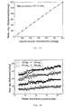
- Fig. 12 shows a typical set of measurements where the measured angular displacement is plotted versus lateral position on the y-axis.
- the object was a 1 mm thick matt steel plate (48 x 180 mm).
- the target distance, d was 200 mm.
- the matt steel surface gave mainly rise to diffusely scattered light.
- the plate was fixed at the bottom position and twisted from the top with a rotational stage from Klinger Scientific (DCS750) Measurements for different twist sites at the top of the plate, corresponding to different displacement axes, were obtained.
- Fig. 12 clearly shows that the sensor can be used to measure the distribution of angular displacement along a twist axis. We used the same relation as the one shown in example 1 to calculate the angular displacement. Again the measurements showed that the determination of angular displacement was insensitive to object distance and distance to the center of rotation.
Landscapes
- Physics & Mathematics (AREA)
- General Physics & Mathematics (AREA)
- Length Measuring Devices By Optical Means (AREA)
Description
- The present invention relates to a method and apparatus for determining angular displacement of one or more parts of an object, said method comprising directing at least one beam of electromagnetic radiation towards one or more parts of the object, detecting speckles from the object surface in at least one first image sensor, and determining one or more speckle displacements before and after the angular displacements of said one or more parts of the object as a function of the angular displacements.
- The invention also relates to a method of determining twist of a rotating shaft subjected to a load; a method of simultaneously determining angular displacements and surface translations of one or more parts of an object; and a method of determining the radius of angular displacement of an object.
- Generally, determination of angular displacement of an object using speckle displacement comprises illumination of the surface of the object by a laser beam. The reflected laser beam generates a speckle pattern which is detected in a linear image sensor. After angular displacement of the object, the displaced speckle pattern is detected in the linear image sensor. The two speckle patterns are then cross-correlated to determine the angular displacement which is provided by the displacement giving maximum cross-correlation.
- A drawback of this method is that the determination of the angular displacement depends on the distance from the linear sensor to the object, movements of the object, the radius of displacement, as well as the shape of the object.
- Hayashi and Kitagawa, "High Resolution Rotation-Angle Measurement of a Cylinder Using Speckle Displacement", Applied Optics, Vol. 22, 1983, p. 3520-3525, disclose a method for measuring the rotation angle of a cylinder, particularly a small rotation angle with high resolution based on the speckle displacement detection in the (near) diffraction field caused by rotation of the cylinder surface. The light intensity distributions of speckles before and after the cylinder surface displacement are detected by a detector array, and displacement of the speckle pattern is measured by computing their cross-correlation function.
- Yamaguchi and Fujita, "Laser Speckle Rotary Encoder", Applied Optics, Vol. 28, No. 20, 1989, p. 4401-4406, disclose a method and apparatus for measuring small rotation angles of a cylinder by detecting displacement of the speckles which appears in the diffraction field of the surface illuminated by a narrow laser beam. The speckle pattern is detected by a linear sensor whose output is cross-correlated before and after the rotation of the cylinder. A resolution of 2 millidegrees is reported.
- In both of these prior art techniques, the angular displacement measurement is dependent of the distance of the linear sensor to the cylinder being measured, longitudinal and transversal movements of the cylinder, its radius, and the shape of the object.
- In an aspect, it is an object of the present invention to provide an improved method and apparatus for determining angular displacements of one or more parts of an object.
- It is a further object of the present invention to provide such a method and apparatus for which the angular displacement determination is independent of the distance to the object, any longitudinal and transversal movements of the object, the shape of the object, and the radius of angular displacement.
- In another aspect, it is the object of the present invention to provide a method and apparatus for determining twist of an object, in particular for determining twist of a rotating object, e.g. a driving shaft, under load.
- In still another aspect, it is the object of the present invention to provide a method and apparatus for determining both angular displacement and surface translation of one or more parts of an object, in particular for determining the radius of angular displacement thereof.
- Further objects will appear from the description of the invention and its preferred embodiments.
- According to an aspect of the invention, there is provided a method for determining angular displacements of one or more parts of an object, said method comprising
- a) directing at least one beam of substantially coherent and substantially parallel electromagnetic radiation towards said one or more parts of the object positioned in a first position;
- b) detecting in at least one first image sensor first one or more distributions of speckles provided by at least a part of the electromagnetic radiation scattered from said one or more parts of the object in said first position;
- c) angular displacing (,ϕ) said one or more parts of the object in a second position;
- d) detecting in said at least one first image sensor second one or more distributions of speckles provided by at least a part of the electromagnetic radiation scattered from said angularly displaced one or more parts of the object in said second position; and
- e) determining one or more displacements (Δx, Δy) of the
first and second detected distributions of the
speckles as a function of the angular displacements
of said one of more parts of the object between said
first and second positions;
wherein - f) the at least a part of electromagnetic radiation scattered from said one or more parts of the object is Fourier transformed by at least one Fourier-transforming means having a Fourier plane, and
- g) the at least one image sensor is being positioned in a detector plane in or near said Fourier plane of said at least one Fourier-transforming means.
-
- Preferred embodiments are claimed in claims 2-7.
- According to another aspect, there is provided an apparatus for determining angular displacements of one or more parts of an object; said apparatus comprising:
- a) means for directing at least one beam of substantially coherent and substantially parallel electromagnetic radiation towards said one or more parts of the object;
- b) at least one first image sensor for detecting first and second one or more distributions of speckles provided by at least a part of the electromagnetic radiation scattered from said one or more parts of the object before and after they are being angularly displaced;
- c) means for determining displacements of the detected first and second one or more distributions of speckles as a function of the angular displacements of said one or more parts of the object;
- d) means for Fourier-transforming at least a part of the electromagnetic radiation scattered from said one or more parts of the object; said means having a Fourier plane in or near the plane of the detecting means of the first and second one or more distributions of speckles.
-
- Preferred embodiments are claimed in claims 9-26.
- It has surprisingly turned out that if
- (f) at least a part of the electromagnetic radiation scattered from said one or more parts of the object is Fourier transformed by a least one Fourier-transforming means having a Fourier plane, and that if
- (g) at least one image sensor is being positioned in a detector plane in or near said Fourier plane of said at least one Fourier-transforming means, it is obtained that determination of the angular displacement is independent of
-
- the distance to the object,
- any longitudinal and transversal movements of the object,
- the wavelength of the source,
- the shape of the object, and
- the radius of angular displacement.
- Generally, according to the invention, the Fourier-transforming means comprises means for providing a Fourier-transformation of the scattered electromagnetic radiation giving rise to linearly displaced speckles due to an angular displacement of the object.
- Or equivalently, the Fourier-transforming means comprises means for Fourier-transforming the angle of direction of the speckles generated by the scattered electromagnetic radiation into a linear coordinate of the speckles near or in the Fourier plane.
- In a preferred embodiment, the linear coordinates of the Fourier-transformed speckles are the distances of speckles to the optical axis of the Fourier-transforming means, said optical axis being both perpendicular to the Fourier plane and perpendicular to the axis of angular displacement.
- Fourier-transforming means are known in the art, see J.W. Goodman, "Introduction to Fourier Optics", McGraw-Hill, 1996.
- In a preferred embodiment, the Fourier-transforming means comprises an optical Fourier-transforming device which Fourier transforms incoming light in the Fourier plane of the device, i.e. in a plane typically coinciding with the focal planes of the Fourier-transforming device.
- Fourier-transforming devices comprise refractive, reflective, and diffractive optical elements, and active liquid crystals, e.g. as disclosed in Goodman, ibid.
- Preferred Fourier-transforming refractive optical elements are selected from refractive lenses whereby simple and readily available optical elements can be used. Refractive convex lenses or cylinder lenses are preferred, whereby simple systems can be made with standard components.
- Reflective systems can be designed by using a parabolic mirror and placing the linear image sensor in the focal point.
- Preferred Fourier-transforming diffractive optical elements are selected from diffractive zone plates and holographic lenses, both of which may be computer generated, whereby particularly compact and robust Fourier-transforming means can be provided. Holographic lenses are preferred. Spherical as well as cylinder lenses can be implemented with diffractive optics.
- In a preferred embodiment, wherein the Fourier-transformed speckles provided by surface elements of one or more parts of the object having different positions along the axis of angular displacement are additionally imaged into corresponding positions of the first image sensor, whereby it is obtained that the distribution of angular displacements along one direction of more parts of an object, typically closely spaced surface elements of the irradiated part of the object, can be determined simultaneously.
- In a particular preferred embodiment, the imaging is performed in one direction while maintaining Fourier-transformation in a direction perpendicular thereto.
- In a preferred embodiment, the Fourier-transforming device and the imaging means are incorporated in a diffractive optical element, whereby a particular compact and robust embodiment is obtained. Methods for incorporating optical elements in diffractive optical elements are known in the art, see e.g. M.T. Gale, "Diffractive Microstructures: Fabrication and Application", Schweizerische Gesellschaft für Mikrotechnik (SGMT)
Bulletin 17, May 1993. - In a preferred embodiment, the Fourier-transforming means, further comprises telescopic means to magnify or reduce the Fourier plane. This is particularly useful for scaling the speckle size to the pixel size of the detector, whereby the maximum resolution can be obtained.
- According to the invention, at least one beam of substantially coherent and substantially parallel electromagnetic radiation is directed towards one or more parts of the object positioned in a first position.
- Suitable electromagnetic irradiation of the object can be provided by methods known in the art.
- More beams of the electromagnetic radiation may be directed towards more parts of the object for simultaneous or subsequent determination of angular displacements of each part.
- The electromagnetic radiations can be generated by the same or different sources.
- In a preferred embodiment, a laser source provides a beam of substantially coherent electromagnetic radiation which beam is split up into two beams irradiating two different parts of the object whereby a particular apparatus can be provided.
- According to the invention, the beam of electromagnetic radiation is substantially coherent for the generation of speckles by constructive and destructive interference of the individual components of the electromagnetic radiation scattered by the object.
- If the beam is completely coherent, the modulation depth of the speckles in the Fourier plane approaches unity, which provides a corresponding high modulation in e.g. the cross-correlation of the detected images of the first and second distributions of the speckles between the first position and the second position of the angularly displaced object.
- If the beam is not sufficiently coherent, the modulation depth of the speckles is low. Consequently, the modulation depth of e.g. the cross-correlation of the detected images decreases, and the pixel position providing maximum cross-correlation is determined with less accuracy and precision.
- Whether the degree of coherence is sufficient for a specific application, e.g. a specific object surface, can be determined by the skilled person according to the methods known in the art, see e.g. J.W. Goodman, "Laser Speckle and Related Phenomena", J.C. Dainty, ed. (Springer-Verlag, Berlin, 1984), Chap. 2.
- It is preferred that the electromagnetic radiation is provided by a laser source, whereby an intensive, parallel beam can be provided. Further, the wavelength can be matched to the spectral sensitivity of the image sensor.
- Suitable laser sources can be selected by a skilled person for a given application, in particular considering coherence and divergence.
- It should be noted that within the present context, the term "substantially coherent electromagnetic radiation" includes incoherent electromagnetic radiation having an induced spatial and temporal coherence. It turns out that the electromagnetic radiation source can be incoherent provided that the spatial coherence length approaches the size of the illuminating spot, and that the temporal coherence length exceeds the depth of the illuminated part of the object.
- According to the invention, the beam of substantially coherent electromagnetic radiation is substantially parallel.
- A non-parallel beam can be accepted, i.e. a diverging or a converging beam. However, if the beam is not sufficient parallel, the determination of the angular displacement becomes dependent on the distance to the object and on the radius of displacement of the object, even when the image sensor is positioned exactly in the Fourier plane.
- The skilled person can determine whether or not a beam is sufficiently parallel for a given application by methods known in the art.
- The wavelength of the electromagnetic radiation can be any wavelength suitable of generating speckles in the Fourier plane of the Fourier-transforming means from the electromagnetic radiation scattered from the object surface. The sensitivity of the image sensor has to match the wavelength of the electromagnetic radiation.
- In a preferred embodiment, the wavelength is a short wavelength, preferably in the range of 0.4 µm to 1.6 µm where suitable image sensors are available.
- Preferred source of substantially coherent electromagnetic radiation comprises laser sources, in particular diode lasers, solid state lasers, and gas lasers.
- According to the invention, first and second one or more distributions of speckles provided by at least a part of the electromagnetic radiation scattered from said one or more parts of the object in a first position and in a second position after angular displacement, respectively, are detected in at least one first image sensor.
- In a particular aspect of the invention, angular displacements and surface translation of one or more parts of an object are determined simultaneously. For this aspect, a second image sensor is positioned in or near the image plane of the object.
- The first and second image sensors can be equal or different.
- In preferred embodiments, the image sensor consists of one- or two-dimensional array detectors.
- In a particular preferred embodiment, the sensitive area of a single detector, pixel, of the array detector has a size which is comparable with the size of a speckle in or near the Fourier plane, whereby a better resolution is obtained.
- In another preferred embodiment, the image sensor is a one-element detector having a short integration time, e.g. a silicon detector, which provides a successively detected image of a timely varying distribution of speckles scattered from a rotating object.
- Preferred embodiments of the first and/or second image sensors comprises array detectors, both one or two one-dimensional array detectors, and two-dimensional array detectors.
- In a particular preferred embodiment, the first and/or second image sensor comprises at least one one-element detector connected to a shift register.
- According to the invention, one or more parts of the object is angularly displaced.
- Generally, the angular displacement can be any angular displacement having a corresponding displacement axis.
- In preferred embodiments, the angular displacement is determined in one or two dimensions.
- In another preferred embodiment, the distribution of angular displacements of more surface elements of the irradiated one or more parts of the object displacement is determined.
- In a particular aspect of the invention, the relative shift in angular displacements of two or more parts of a rotating object, in particular a rotating shaft, subjected to a load is determined.
- According to the invention, one or more displacements between the first and second distributions of the Fourier-transformed speckles detected in the first image sensor, or the speckles detected in the second image sensor, are obtained by cross-correlating the detected images thereof as a function of the angular displacements of said one or more parts of the object between said first and second positions.
- Suitable cross-correlation techniques of electronically recorded and sampled images are known in the art, see J.S. Bendat and A.G. Piersol, "Random Data Analysis and Measurement Procedures", (John Wiley & Sons, 1986).
- In a preferred embodiment, cross-correlation is performed by a method disclosed in M. Sjödahl, "Electronic Speckle Photography: Increased Accuracy by Nonintegral Pixel Shifting", Applied Optics, Vol. 33, 1994, p. 6667-6673, whereby an automatic determination of the pixel position of maximum cross-correlation is achieved.
- The pixel position of maximum cross-correlation provides a measure for the linear displacement of the speckles in the Fourier plane or in the image plane, respectively, i.e. a linear displacement which is proportional to the applied angular displacement, whereby this angular displacement of the object can be determined.
- Generally, speckles arise when diffusely scattered electromagnetic radiation, e.g. scattered light from a surface having irregularities smaller than the wavelength of the incident radiation, interferes with each other or with electromagnetic radiation scattered from macrostructures in the surface, e.g. light scattered from irregularities larger than the wavelength of the incident radiation. The generated field is either Fourier-transformed into a speckle pattern in the Fourier plane, or the object is imaged into an imaged speckle pattern in the image plane, or both.
- In a preferred embodiment, surfaces having a major proportion of diffusely scattered light can be applied.
- If the object surface does not exhibit a suitable modulation of the detected speckles, the surface may be treated by methods known in the art.
- Preferred treatments of the object surface comprise mounting retroreflective tape, sandblasting the surface, matting the surface.
- According to another aspect of the invention, there is provided a method of determining twist of a rotating object, e.g. a shaft, between two or more parts of the rotating object subjected to a load. The twist can be calculated from the determined relative shift in angular displacements (1/2) and their mutual distance d12 at two or more positions on the object using the formula: twist = (1 - 2)/d12 (deg/m).
- This method is advantageous since it is a non-contact method, independent on distance to the object, any longitudinal or transversal movements of the object, the shape of the object, and the radius of rotation. Further the calibration is independent on the wavelength of the source.
- According to still another aspect of the invention, there is provided a method of simultaneously determining angular displacement and surface translation of one or more parts of an object.
- This method is advantageous since it is a non-contact method.
- According to still another aspect of the invention, there is provided a method of determining the radius of angular displacement of one or more parts of an object.
- This method is advantageous since it is a non-contact method.
- In the following, the invention is further disclosed with detailed description of preferred embodiments, reference being made to the drawings in which
- Figs. 1A-1D show cross-sectional sketches of preferred embodiments of carrying out directing the at least one beam of substantially coherent and substantially parallel electromagnetic radiation towards said one or more parts of an object;
- Fig. 2 shows a cross-sectional sketch of a preferred embodiment of carrying out detecting in at least one first image sensor first and second one or more distributions of the Fourier-transformed speckles provided by at least a part of the electromagnetic radiation scattered from said one or more parts of the object in said first and second positions;
- Fig. 3 shows a longitudinal, cross-sectional sketch of a preferred embodiment of carrying out detecting said first and second one or more distributions of the Fourier-transformed speckles from two far spaced parts of the object;
- Figs. 4A and 4B show longitudinal and cross-sectional sketches of a preferred embodiment of carrying out detecting said first and second one or more distributions of Fourier-transformed speckles from more closely spaced parts of the object;
- Figs. 5A and 5B show longitudinal and cross-sectional sketches of a preferred embodiment of carrying out detecting said first and second one or more distributions of the Fourier-transformed speckles, and detecting first and second one or more distributions of imaged speckles for measuring angular displacement and surface translation and determination of the radius of displacement with respect to the displacement axis;
- Figs. 6A and 6B show other cross-sectional sketches of a preferred embodiment of carrying out detecting said first and second one or more distributions of Fourier-transformed speckles for measuring two-dimensional tilt of an object;
- Figs. 7A and 7B show longitudinal and cross-sectional sketches of a preferred embodiment of carrying out detecting said first and second one or more distributions of the Fourier-transformed speckles from two far spaced parts of the object for measuring twist thereof;
- Figs. 8A and 8B show longitudinal and cross-sectional sketches of a preferred embodiment of carrying out detecting said first and second one or more distributions of the Fourier-transformed speckles from two closely spaced parts of the object for dynamically measuring the distribution of angular displacements thereof;
- Figs. 9A and 9B show longitudinal and cross-sectional sketches of a preferred embodiment similar to those shown in Figs. 7 and 8, except for the image sensor being of a one-element detector with a shift register or a means for storing the temporal behaviour of the detector signal in a memory array;
- Fig. 10 shows a cross-sectional sketch of a preferred embodiment of the Fourier-transforming means which comprises telescopic means to magnify or reduce the Fourier plane;
- Fig. 11 shows a plot of measured angular displacement of a matt aluminium cylinder versus applied angular displacement; and
- Fig. 12 shows plots of measured angular displacements versus various heights close to the bottom of a twisted matt steel plate for applied angular displacements at its top.
-
- In the following illustrations in Fig. 1A-1D the source of electromagnetic radiation is a laser source.
- Fig. 1A shows a cross-sectional sketch of a preferred embodiment for carrying out directing the at least one beam of substantially coherent and substantially parallel electromagnetic radiation towards said one or more parts of the object positioned in a first or in a second position.
- The irradiating beam may be either divergent or parallel irrespectively of the image sensor and the Fourier-transforming means. Further, the irradiating beam can be propagating inside or outside the Fourier-transforming means.
- In this example, a slightly divergent beam of
light 11a is directed towards a part of acylinder 10 before and after the cylinder is angularly displaced clockwise between two positions A and B about an axis ofdisplacement 19 perpendicular to the optical axis O. - The
divergent beam 11a is provided by converging aspherical wave 12 of coherent light from alaser point source 13, positioned within the focal distance f1 of thebeam forming lens 14. If the point source is positioned outside the focal distance, the beam will be convergent. Thelight source 13 can be operated either in a pulsed mode or it can be run continuously. - In this example, the
beam forming lens 14 is positioned in a distance d1 to theobject plane 10a. However, the distance from thebeam forming lens 14 to theobject plane 10a can be chosen arbitrarily. - In another embodiment (not illustrated), the
beam forming lens 14 collimates thespherical wave 12 into a parallel beam; said point source being placed in the focal point of thelens 14. - The
beam forming lens 14 can be any suitable lens or lens system. It can be chosen by a skilled person depending on the preferred parameters of the beam for a specific application. - Fig. 1B shows another embodiment of carrying out directing the at least one beam of substantially coherent and substantially parallel beam of
electromagnetic radiation 11b (source not shown) towards said one or more parts of theobject 10. In this example, a beam ofelectromagnetic radiation 11b, which can be provided as described in connection with Fig. 1A, is propagating outside of the Fourier-transformingmeans 16. For illustration in this embodiment, thedetector plane 17 of theimage sensor 18 is positioned asymmetrically with respect to theoptical axis 0 near theFourier plane 15 of the Fourier-transformingmeans 16. - Fig. 1C shows still another embodiment of carrying out directing the at least one beam of substantially coherent and substantially parallel beam of
electromagnetic radiation 11c (source not shown) towards said one or more parts of theobject 10. Asemi-transparent mirror 20, or an ordinary mirror, directs a substantially parallel and substantially coherent beam ofelectromagnetic radiation 11c towards said one or more parts ofobject 10, so that said beam of electromagnetic radiation is centered around theoptical axis 0 of the Fourier-transformingmeans 16. For illustration in this embodiment, the detector plane of theimage sensor 18 coincides with theFourier plane 15 of theFourier transforming means 16. - Fig. 1D shows still another embodiment of carrying out directing the at least one beam of substantially coherent and substantially parallel beam of
electromagnetic radiation 11d (source not shown) towards said one or more parts of theobject 10. The source ofelectromagnetic radiation 13 is placed off-axis to the optical axis O in theFourier plane 15, i.e. it is placed transversely to the optical axis O, e.g. to provide space for animage sensor 18 having a detector plane which coincide with theFourier plane 15 of the Fourier-transformingmeans 16. Theimage sensor 18 is being close to or centered asymmetrically about the optical axis. The Fourier-transforminglens 16 is used to provide a substantially parallel and substantially coherent beam ofelectromagnetic radiation 11d which is directed towards one or more parts of theobject 10 inside the aperture of aFourier transforming means 16. The source orelectromagnetic radiation 13 can be placed arbitrarily in theFourier plane 15. - Fig. 2 shows a cross-sectional sketch of a preferred embodiment for carrying out the detection of said at least a part of the electromagnetic radiation scattered from said one or more parts of the object in said first and second positions.
- In this example, irradiation of only one part of the object is assumed. A substantially parallel and substantially coherent beam of light (
11a cylinder 10 similar to the beams (11a - It should be noted that other parts of the object could be irradiated in parallel, as illustrated in later examples, in order to simultaneously determine angular displacements of these other parts of the object.
- Further, the object is angularly displaced in one dimension only. In this example the
object 10 is angularly displaced the angle with respect to thedisplacement axis 19. An example illustrating angular displacement in two dimensions is provided below. - In the blown up part of Fig. 2, there are shown two positions A and B of the object, i.e. the positions before and after the angular displacement of the object, respectively. The irradiated part of the object is angularly displaced the angle from the position A to the second position B about the
displacement axis 19 in a clockwise direction as indicated by the arrow. In this position B, at least a part of the electromagnetic radiation scattered from this part of the object is reflected in areflection 21B in anangle 2 with respect to thereflection 21A in position A. - In the detector plane coinciding exactly with the
Fourier plane 15, an angular displacement of the Fourier-transformed reflections is mapped into a linear displacement Δx(2) on theimage sensor 18. Thus, the first detected intensity distribution ofspeckles 22A in position A is linearly displaced into the second intensity distribution ofspeckles 22B in position B. - Each surface element of the irradiated surface of the
object 10 provides a spherically scattered reflection that is diffusely and/or specularly scattered therefrom. Thosereflections aperture boundaries 23 of the Fourier-transforming means, in this example alens 16, will be the Fourier transforming means. - First and second one or more distributions of speckles are detected in at least one image sensor, i.e. the Fourier-transformed wave patterns before and after angular displacement are detected in said at least one image sensor as distributions of speckles, viz. constructive and destructive interferences of said Fourier-transformed components of the reflection. In this example, the first 22A and second 22B Fourier-transformed wave patterns provide distributions of speckles before and after the angular displacement of the object, respectively, which are detected in the image sensor; said image sensor being positioned exactly in the
Fourier plane 15 of thelens 16. The exact position of the image sensor is not essential as long as it is positioned in or near the Fourier plane. - In this example, the image sensor is a one-dimensional array detector of 512 pixels, RL0512G supplied from EG&G RETICON, USA.
- In order to maintain a good precision for large angular displacements, it is preferred to measure the angular displacement in sections using each preceding section as reference for the succeeding section. In yet another preferred embodiment, the reference speckle patterns, said first positions are pre-recorded at known fixpoints and stored in a memory array. After the applied angular displacement of the object, the current speckle pattern, said second position, is recorded and the displacement relative to the fixpoints is calculated. This method is in particular advantageous for absolute rotation encoder applications.
- A measure for the size of the section can be obtained from the peak value of the cross-correlation. When the peak value drops to a value below a given threshold (80 %), the reference signal is replaced by the present one and the speckle displacement is added up. (See e.g. M. Sjödahl and I. Yamaguchi, "Strain and Torque Measurements on Cylindrical Objects Using the Laser Speckle Strain Gauge", Optical Engineering, Vol. 35, p. 1179-1186, 1996).
- An illustration of the determination of angular displacement of 0-600 mdeg is shown in Example 1.
- Fig. 3 shows another cross-sectional sketch of a preferred embodiment for carrying out detecting said first and second one or more distributions of the Fourier-transformed speckles from two far-spaced parts of the object.
- In this example, irradiation and detection of two far-spaced parts of the object is assumed. Two substantially parallel and substantially coherent beams of light irradiate the two selected part of the
cylinder 10 separated along the longitudinal axis of the object, in analogy to the onepart irradiation 11a - The angular displacements of the two parts of the object are determined as illustrated for the embodiment shown in fig. 2.
- It should be noted that the two irradiation and detection configurations can be equal or different.
- The two angular displacements can be used to determine the twist of the object provided the distance between the two parts of the object is known.
- Figs. 4A and 4B show cross-sectional sketches of a preferred embodiment for carrying out detecting said first and second one or more distributions of Fourier-transformed speckles from more closely spaced parts of the object.
- This example illustrates an embodiment that extends the determination of the two one-dimensional angular displacements of two far spaced parts of an object as shown in Fig. 3 to the determination of more one-dimensional angular displacements of more closely spaced parts of the object.
- The Fourier-transforming means additionally comprises a
cylindrical lens 16b inserted between theobject 10 and the Fourier-transforminglens 16a in order to perform the necessary imaging along the axis of the shaft. - The
object 10 can be placed arbitrarily, but it is preferably placed in or near the focal plane of the cylindrical lens. - The
cylindrical lens 16b performs imaging in the y-direction whereby surface elements on the irradiated part of the object having different heights are imaged on corresponding heights of theimage sensor 18, here a two-dimensional array detector placed in or near the Fourier plane of the Fourier-transforminglens 16a. - The distance between the
cylindrical lens 16b and the Fourier-transforminglens 16a can be chosen arbitrarily. - The distribution of angular displacements versus y-position of the part of the object irradiated can be determined as the distances between the surface elements of the object, corresponding to the y-lines in the two-dimensional array detector, are known from the geometrical magnification in the y-direction given by methods known in the art, see e.g. A.E. Siegman, "Lasers", University Science Books, USA, 1986.
- Fig. 5 shows a cross-sectional sketch of a preferred embodiment for carrying out the detection of said at least a part of the electromagnetic radiation scattered from said one or more parts of the object in said first and second positions in which the surface translation is additionally determined.
- This embodiment is similar to the embodiment shown in Fig. 2, except that surface translation is additionally detected by a
second image sensor 18b placed in or near theimage plane 15b of theobject 10, and except that thefirst image sensor 18a detecting the Fourier-transformed speckles is placed in the Fourier plane. If thesecond image sensor 18b is placed outside theFourier plane 15a, preferably in or near theimage plane 15b positioned 2f from the Fourier-transforminglens 16, then the translation of the surface originating from the angular displacement of theobject 10 towards a linear displacement of the distribution of speckles detected therein. By determining the angular displacement and the corresponding surface translation of theobject 10, in bothimage sensors Fourier lens 16 to the image sensor placed in or near the image plane, and the radius of angular displacement. - Figs. 6A and 6B show cross-sectional sketches of a preferred embodiment for carrying out detecting said first and second one or more distributions of Fourier-transformed speckles for measuring two-dimensional tilt of an object.
- In this example, irradiation of only one part of the object, here exemplified by a plate, is illustrated.
- It is assumed that a substantially parallel and substantially coherent beam of light irradiates a selected part of the
plate 10 similar to the beams oflight - The object is angularly displaced in two dimensions; in this example the
object 10 is angularly displaced the angle with respect to thedisplacement axis 19a, and angularly displaced the angle ϕ with respect to thedisplacement axis 19b. - This preferred embodiment is similar to the embodiment shown in Fig. 2, except for the
image sensor 18 which is a two dimensional array detector of a standard type ccd camera without a lens, e.g. TI-22 CCD camera from NEC, Japan. - From the position A, the
plate 10 is angularly displaced the angle in the x-direction, and the angle ϕ in the y-direction, whereby a surface element moves to position B. In total, an angular displacement of ,ϕ degrees of the target provides a rotation of 2,2ϕ degrees of the reflection. - The
displacement 2,2ϕ of the reflection is mapped into a linear displacement in the xy-plane on theimage sensor 18 placed in or near the Fourier plane. - The two-dimensional displacement can be determined with the same advantages as those described for the one-dimensional displacement in connection with Fig. 2.
- In particular, the two-dimensional array detector provides the advantages of a very compact image sensor compared to the alternative of two one-dimensional array detectors. In particular cases, however, the two-dimensional array detector can be substituted by two one-dimensional array detectors.
- Figs. 7A and 7B show longitudinal and cross-sectional sketches of a preferred embodiment of carrying out detecting said first and second one or more distributions of the Fourier-transformed speckles from two far spaced parts of the object for measuring the relative shift in angular displacements thereof. The relative shift in the two angular displacements can be used to determine the twist of the object provided the distance between the two parts of the object is known.
- In this example, a high power pulsed laser, e.g. SDL-2100-E1 from SDL, USA, irradiates in a strobed mode a cylinder similar to that shown in Fig. 3.
- In at least one
first image sensor 18 first one or more distributions of Fourier-transformed speckles from two far-spaced parts of acylinder 10 are detected before and after aload 71 is applied to the cylinder. The strobed laser pulse before and after loading the object should preferably be positioned at approximately the same overall angular position of the shaft. A slight change in the timing between the angular position of the strobe pulses can be compensated for in the subsequent data analysis. - Fig. 8A and 8B show longitudinal and cross-sectional sketches of a preferred embodiment of carrying out detecting said first and second one or more distributions of the Fourier-transformed speckles from two or more closely spaced parts of the object for dynamically measuring the relative shift in angular displacements thereof.
- In this example irradiation of the object is performed as for Figs. 7A and 7B.
- However, instead of measuring the relative shift in angular displacements between far spaced parts of the rotating shaft as in Figs. 7A and 7B, the distribution of relative shift in angular displacements between closely spaced parts of the rotating shaft, similar to that in Figs. 4A and 4B, are determined. Further, as for the embodiment shown in Figs. 7A and 7B a slight change in the timing between the angular position of the strobe pulses can be compensated for in the subsequent data analysis. The axial distribution of angular displacements can thus be probed revealing the twist of the shaft.
- Figs. 9A and 9B show longitudinal and cross-sectional sketches of a preferred embodiment similar to those shown in Figs. 7 and 8, except for the image sensor being of a one-element detector with a shift register.
- In this example irradiation of the object is performed as for either Fig.3 or Figs. 7A or 7B.
- However, instead of using an array detector, one or more one-
element detectors 18 with shift registers 91 distributed along the shaft axis are used. - This embodiment of the image sensor has the advantage of being extremely fast compared to one- and two-dimensional array detectors.
- Storing of the temporal information in the shift register of the signal can be performed in a digital storage memory in an oscilloscope or in a digital computer after digitizing the analogue detector signal.
- The linear displacements Δx,Δy between the first and second distributions of speckles, both Fourier-transformed speckles and imaged speckles, are determined by cross-correlating the detected images thereof as a function of the angular displacements ,ϕ of said one or more parts of the object.
- Cross-correlation of the detected images, e.g. recorded signals from the
image sensor 18 before and after angular displacement of the irradiated part of the object, are obtained by methods known in the art. - In the examples, the displacement between the first 22a and second 22b distributions of the Fourier-transformed speckles, and the first and second distributions of recorded
speckles 51, are determined by calculating the position for maximum cross correlation between the two signals from the image sensor using an algorithm disclosed in M. Sjödahl, ibid. - The position for maximum cross-correlation is calibrated against known angular displacements provided by a rotation stage from Klinger Scientific (DCS750) with a stated resolution of 1 mdeg.
- The at least a part of the electromagnetic radiation scattered from said one or more parts of the object is Fourier transformed by at least one Fourier-transforming means having a Fourier plane. In the examples, the Fourier-transforming means is illustrated by a converging
lens 16. - In Fig. 10 a preferred embodiment is shown in which a telescopic set of
lenses Fourier plane 15 to thedetector plane 17 of theimage sensor 18. - Generally, the position of the
image sensor 18 in thedetector plane 17 can be symmetrical or asymmetrical with respect to the intercept of theoptical axis 0. In the example shown in Fig. 2, a symmetrical configuration is illustrated. - The object surface should be able to generate speckles.
- In all the illustrated embodiments, the surfaces of the aluminium cylinders and steel plates have been sandblasted.
- The invention is further illustrated by the following in examples.
- An apparatus according to the one shown in Fig. 1C and Fig. 2 was provided with the exception that the
image sensor 18, a linear array sensor RL0512-G from EG&G Reticon, placed exactly in the Fourier plane. The signals from the image sensor, before and after angular displacement of 0.6 degrees in total, of theobject 10 a matt aluminium cylinder with a radius of 15 mm, were cross-correlated in a personal computer by calculating the empirical cross-correlation coefficient as described above, and the linear displacement of the speckles in the Fourier plane was determined by the method of M. Sjodahl. - Fig. 11 shows a typical set of measurements where the measured angular displacement is plotted versus the applied angular displacement of 0-600 mdeg for a matt aluminium cylinder with a radius of 15 mm. Similar measurements were obtained for matt aluminium cylinders having radius of 10 and 20 mm. The object distance, d, was 100 mm. Measurements with object distances of 90 and 110 mm showed similar results. The matt aluminium surface gave mainly rise to diffusely scattered light. The measurements were performed in steps of 50 mdeg, and the angular displacement was applied with a rotational stage from Klinger Scientific (DCS750) with a resolution of 1 mdeg. From Fig. 11 it can be seen that the measured angular displacements equal the applied angular displacements. The measured linear displacement Δx is converted to angular displacement , using the relation:
- An apparatus according to the one shown in Fig. 1C and Fig. 6 was provided with the exception that the
image sensor 18, a two-dimensional image sensor TI-22 CCD Camera from NEC, Japan, placed exactly in the Fourier plane, and with the exception that the object was a matt steel plate. The signals from the individual lines on the image sensor, before and after angular displacement of the steel plate, were cross-correlated in a personal computer, and the displacement Δx that provided maximum cross-correlation between the two signals from the image sensor was determined by the method of M. Sjödahl. - Fig. 12 shows a typical set of measurements where the measured angular displacement is plotted versus lateral position on the y-axis. The object was a 1 mm thick matt steel plate (48 x 180 mm). The target distance, d, was 200 mm. The matt steel surface gave mainly rise to diffusely scattered light. The plate was fixed at the bottom position and twisted from the top with a rotational stage from Klinger Scientific (DCS750) Measurements for different twist sites at the top of the plate, corresponding to different displacement axes, were obtained. Fig. 12 clearly shows that the sensor can be used to measure the distribution of angular displacement along a twist axis. We used the same relation as the one shown in example 1 to calculate the angular displacement. Again the measurements showed that the determination of angular displacement was insensitive to object distance and distance to the center of rotation.
Claims (29)
- A method for determining angular displacements of one or more parts of an object (10), said method comprisinga) directing at least one beam of substantially coherent and substantially parallel electromagnetic radiation (11) towards said one or more parts of the object positioned in a first position (A);b) detecting in at least one first image sensor (18) first one or more distributions of speckles (22A) provided by at least a part (21A) of the electromagnetic radiation scattered from said one or more parts of the object in said first position;c) angular displacing (,ϕ) said one or more parts of the object in a second position (B);d) detecting in said at least one first image sensor (18) second one or more distributions of speckles (22B) provided by at least a part (21B) of the electromagnetic radiation scattered from said angularly displaced one or more parts of the object in said second position; ande) determining one or more displacements (Δx, Δy) of the first and second detected distributions of the speckles as a function of the angular displacements of said one of more parts of the object between said first and second positions;
whereinf) the at least a part of electromagnetic radiation scattered from said one or more parts of the object is Fourier transformed by at least one Fourier-transforming means (16) having a Fourier plane (15), andg) the at least one first image sensor is being positioned in a detector plane (17) in or near said Fourier plane of said at least one Fourier-transforming means. - A method according to claim 1, wherein(h) first and second one or more distributions of speckles, provided by at least a part of the electromagnetic radiation scattered from said one or more parts of the object in said first (A) and second (B) positions, are detected in at least one second image sensor (18b) not positioned in or near the Fourier plane, and wherein(i) one or more displacements of said first and second one or more distributions of speckles detected in the second image sensor are determined as a function of the angular displacements of said one or more parts of the object between said first and second positions.
- A method according to claim 1 or 2, wherein the Fourier-transformed speckles provided by surface elements of one or more parts of the object having different positions along the axis of angular displacement (19) are additionally imaged into corresponding positions of the first image sensor.
- A method according to claim 3, wherein the Fourier-transformed and additionally imaged speckles are detected in the first image sensor in lines perpendicular to the axis of angular displacement.
- A method according to one of claims 1-4, wherein the detection in the at least one first or second image sensors comprises simultaneous detection of one or more distributions of static speckles.
- A method according to one of claims 1-4, wherein the detection in the at least one first or second image sensors comprises successive detection of one or more distributions of dynamic speckles.
- A method according to one of claims 1-6, wherein the determination of displacements of the detected first and second one or more distributions of speckles are determined by the pixel position of maximum cross-correlation.
- An apparatus determining angular displacements of one or more parts of an object (10); said apparatus comprising:a) means directing at least one beam of substantially coherent and substantially parallel electromagnetic radiation (11) towards said one or more parts of the object;b) at least one first image sensor detecting (18) first and second one or more distributions of speckles (22A, 22B) provided by at least a part (21A, 21B) of the electromagnetic radiation scattered from said one or more parts of the object before and after they are being angularly displaced;c) means determining displacements of the detected first and second one or more distributions of speckles as a function of the angular displacements of said one or more parts of the object;d) means Fourier-transforming at least a part of the electromagnetic radiation scattered from said one or more parts of the object; said means having a Fourier plane in or near the plane of the detecting means of the first and second one or more distributions of speckles.
- An apparatus according to claim 8, which additionally comprises at least one second image sensor (18b), not positioned in or near the Fourier plane.
- An apparatus according to claim 9, wherein the second image sensor is positioned near or in the image plane of the object.
- An apparatus according to one of claims 8-10, which further comprises imaging means for imaging in one direction while maintaining Fourier-transformation in a direction perpendicular thereto.
- An apparatus according to claim 11, wherein the imaging means is a cylindrical lens.
- An apparatus according to one of claims 8-12, wherein the Fourier-transforming means comprises Fourier-transforming devices comprising refractive, reflective, and diffractive optical elements; and active liquid crystals; and combination of these.
- An apparatus according to claim 13, wherein the Fourier-transforming refractive optical elements are selected from the group consisting of convex lenses and cylinder lenses.
- An apparatus according to claim 13, wherein the Fourier-transforming diffractive optical elements are selected from the group consisting of diffractive zone plates and holographic lenses.
- An apparatus according to one of claims 11-15, wherein the Fourier-transforming means and the imaging means are incorporated in a single diffractive optical element.
- An apparatus according to one of claims 8-16, wherein the Fourier-transforming means further comprises telescopic means to magnify or reduce the Fourier plane.
- An apparatus according to one of claims 8-17, wherein the first image sensor is positioned in or near the optical axes (0) of said at least one Fourier transforming means.
- An apparatus according to one of claims 8-18, wherein the first and/or second image sensor comprises at least one array detector.
- An apparatus according claim 19, wherein the array detector consists of one one-dimensional array detector.
- An apparatus according claim 19, wherein the array detector consists of two one-dimensional array detectors.
- An apparatus according claim 19, wherein the array detector consists of a two-dimensional array detector.
- An apparatus according to one of claims 8-18, wherein the first and/or second image sensor comprises at least one one-element detector connected to a shift register.
- An apparatus according to one of claims 19-23, wherein a single detector of the array detector or the one-element detector connected to a shift register has a sensitive area of a size comparable with the size of a speckle in or near the Fourier plane.
- An apparatus according to one of claims 8-24, wherein the first image sensor is positioned exactly in the Fourier plane.
- An apparatus according to one of claims 8-25, wherein the electromagnetic radiation is laser light.
- A method of determining twist of a rotating object (10) between two or more parts of the object subjected to a load (71) comprisinga) determining the relative shift in angular displacements of one or more parts of the rotating object before and after loading the object, said angular displacements being determined according to the method as claimed in one of claims 1-7, and/or being determined using an apparatus as claimed in one of claims 8-26;
wherein the substantially coherent and substantially parallel electromagnetic radiation directed towards the object is pulsed with a pulse length which allows strobing of the rotating object so that a first and a second one or more distributions of the Fourier-transformed speckles generated by the at least a part of the electromagnetic radiation scattered from said two or more parts of the object are detected before and after the loading of the object,b) and determining the twist between said two or more parts of the object from the determined relative shift in angular displacements and their mutual distances. - A method of simultaneously determining angular displacements and surface translations of one or more parts of an object comprisinga) determining the angular displacement of one or more parts of the object before and after the angular displacement, said angular displacement being determined according to the method as claimed in one of claims 1-7, and/or being determined using an apparatus as claimed in one of claims 8-26,b) and simultaneously determining the linear displacement of said one or more parts of the object before and after the angular displacement by detecting speckles of said one or more parts of the object in at least one second image sensor (18b) positioned in or near the image plane (17b) of the Fourier-transforming means (16).
- A method of determining the radius of angular displacement of one or more parts of an object comprising
simultaneously determining angular displacements and surface translations of one or more of said parts of the object by the method as claimed in claim 28, and determining the radius of angular displacements from said simultaneously determined angular displacements and surface translations.
Applications Claiming Priority (3)
| Application Number | Priority Date | Filing Date | Title |
|---|---|---|---|
| DK56597 | 1997-05-16 | ||
| DK56597 | 1997-05-16 | ||
| PCT/DK1998/000191 WO1998053271A2 (en) | 1997-05-16 | 1998-05-15 | Method and apparatus for determining angular displacement, surface translation, and twist |
Publications (2)
| Publication Number | Publication Date |
|---|---|
| EP1019668A2 EP1019668A2 (en) | 2000-07-19 |
| EP1019668B1 true EP1019668B1 (en) | 2002-07-31 |
Family
ID=8094985
Family Applications (1)
| Application Number | Title | Priority Date | Filing Date |
|---|---|---|---|
| EP98921364A Expired - Lifetime EP1019668B1 (en) | 1997-05-16 | 1998-05-15 | Speckle methods and apparatus for determining angular displacement, surface translation, and twist |
Country Status (5)
| Country | Link |
|---|---|
| US (1) | US6248994B1 (en) |
| EP (1) | EP1019668B1 (en) |
| AU (1) | AU7424798A (en) |
| DE (1) | DE69806952T2 (en) |
| WO (1) | WO1998053271A2 (en) |
Families Citing this family (18)
| Publication number | Priority date | Publication date | Assignee | Title |
|---|---|---|---|---|
| WO1996002009A1 (en) | 1994-07-08 | 1996-01-25 | Forskningscenter Risø | An optical measurement method and apparatus |
| JP2001304816A (en) * | 2000-04-26 | 2001-10-31 | Kenichiro Kobayashi | Travel measuring system and apparatus using granular dot pattern by laser reflected light |
| US6642506B1 (en) * | 2000-06-01 | 2003-11-04 | Mitutoyo Corporation | Speckle-image-based optical position transducer having improved mounting and directional sensitivities |
| US7065258B2 (en) * | 2001-05-21 | 2006-06-20 | Mitutoyo Corporation | Systems and methods for reducing accumulated systematic errors in image correlation displacement sensing systems |
| EP2400260A1 (en) | 2002-02-14 | 2011-12-28 | OPDI Technologies A/S | Optical displacement sensor |
| US20040011149A1 (en) * | 2002-04-03 | 2004-01-22 | David Carroll | Integrated angular and radial position sensor |
| JP2007064864A (en) * | 2005-09-01 | 2007-03-15 | Toyo Seiki Seisakusho:Kk | Strain measuring method and device therefor |
| KR101320520B1 (en) * | 2006-11-06 | 2013-10-22 | 삼성전자주식회사 | Method and apparatus for calibarting position of image sensor, and method for detecting position of image sensor |
| CN102607468B (en) * | 2012-03-09 | 2013-08-21 | 方平 | Small-angle displacement sensor based on double-channel grating |
| CN102589447B (en) * | 2012-03-09 | 2014-01-29 | 方平 | Micro linear displacement sensor based on two-channel grating |
| CZ2013164A3 (en) * | 2013-03-05 | 2014-01-02 | Univerzita Palackého | Method of contactless detection of moving object absolute position by making use of coherence granularity phenomenon and apparatus for making the same |
| WO2015012071A1 (en) * | 2013-07-23 | 2015-01-29 | 京都電子工業株式会社 | Rotational speed detection device, viscosity measurement device using said device, rotational speed detection method, and rotating body used in said method |
| US9773190B2 (en) * | 2013-12-10 | 2017-09-26 | National Chung-Shan Institute Of Science And Technology | Precision calibration method for high-precise rotary encoder |
| US9574915B1 (en) * | 2015-12-22 | 2017-02-21 | National Chung-Shan Institute Of Science & Technology | Precision calibration method for high-precise rotary encoder |
| US10883818B2 (en) | 2016-02-25 | 2021-01-05 | ContinUse Biometrics Ltd. | Optical transforming and modulated interference pattern of a moving object |
| US12144685B2 (en) * | 2019-12-13 | 2024-11-19 | Korea Advanced Institute Of Science And Technology | Method and apparatus for quantitative ultrasound imaging using single-ultrasound probe |
| IL294563B1 (en) * | 2020-01-14 | 2026-04-01 | Pxe Computational Imaging Ltd | System and method for optical imaging and measurement of objects |
| CN115166201B (en) * | 2022-07-01 | 2024-06-14 | 山东交通学院 | Novel quantitative analysis method for slope stability |
Family Cites Families (6)
| Publication number | Priority date | Publication date | Assignee | Title |
|---|---|---|---|---|
| US3419330A (en) * | 1965-04-06 | 1968-12-31 | Sperry Rand Corp | Diffraction grating angular rate sensor |
| CH548607A (en) * | 1971-05-05 | 1974-04-30 | Hasler Ag | DEVICE FOR MEASURING THE RELATIVE SPEED AND / OR THE DISPLACEMENT TRAVEL OF A BODY PARALLEL TO A SURFACE. |
| EP0024167A3 (en) * | 1979-08-07 | 1982-08-04 | Rolls-Royce Plc | Method and apparatus for speckle pattern interferometric determination of point displacements |
| US4525068A (en) * | 1982-09-17 | 1985-06-25 | General Electric Company | Torque measurement method and apparatus |
| GB9012004D0 (en) * | 1990-05-30 | 1990-07-18 | Univ Southampton | Laser torquemeter |
| DK120692D0 (en) * | 1992-09-30 | 1992-09-30 | Risoe Forskningscenter | ROTATION SMALL LING |
-
1998
- 1998-05-15 WO PCT/DK1998/000191 patent/WO1998053271A2/en not_active Ceased
- 1998-05-15 DE DE69806952T patent/DE69806952T2/en not_active Expired - Fee Related
- 1998-05-15 AU AU74247/98A patent/AU7424798A/en not_active Abandoned
- 1998-05-15 EP EP98921364A patent/EP1019668B1/en not_active Expired - Lifetime
-
1999
- 1999-11-15 US US09/440,574 patent/US6248994B1/en not_active Expired - Fee Related
Non-Patent Citations (3)
| Title |
|---|
| HAYASHI A. ET AL.: "High-resolution rotation-angle measurement of a cylinder using speckle displacement detection", APPLIED OPTICS, vol. 22, no. 22, 15 November 1983 (1983-11-15), WASHINGTON DC (US), pages 3520 - 3525, XP055003398, DOI: doi:10.1364/AO.22.003520 * |
| SJÖDAHL M. ET AL.: "Strain and torque measurements on cylindrical objects using the laser speckle strain gauge", OPTICAL ENGINEERING, vol. 35, no. 4, 1 April 1996 (1996-04-01), BELLINGHAM WA (US), pages 1179 - 1186, XP000632742, DOI: doi:10.1117/1.600606 * |
| YAMAGUCHI I. ET AL.: "Laser speckle rotary encoder", APPLIED OPTICS, vol. 28, no. 20, 15 October 1989 (1989-10-15), WASHINGTON DC (US), pages 4401 - 4406, XP000071283 * |
Also Published As
| Publication number | Publication date |
|---|---|
| US6248994B1 (en) | 2001-06-19 |
| WO1998053271A2 (en) | 1998-11-26 |
| WO1998053271A3 (en) | 1999-02-25 |
| DE69806952D1 (en) | 2002-09-05 |
| AU7424798A (en) | 1998-12-11 |
| DE69806952T2 (en) | 2002-11-21 |
| EP1019668A2 (en) | 2000-07-19 |
Similar Documents
| Publication | Publication Date | Title |
|---|---|---|
| US6248994B1 (en) | Method and apparatus for determining angular displacement, surface translation, and twist | |
| US4708483A (en) | Optical measuring apparatus and method | |
| US8810800B2 (en) | Dimensional probe and methods of use | |
| EP0880676B1 (en) | Apparatus and methods for surface contour measurement | |
| US4897536A (en) | Optical axis displacement sensor with cylindrical lens means | |
| CN106767545A (en) | A kind of high accuracy high-space resolution angel measuring instrument and angle measurement method | |
| US5684596A (en) | Method and apparatus for measuring axial and torsional loads on a valve stem | |
| US4009965A (en) | Method and apparatus for determining object dimension and other characteristics using diffraction waves | |
| EP0671007B1 (en) | Method and apparatus for determining the rate of angular rotation of a rotating object | |
| Heikkinen et al. | A geometric model of surface motion measurement by objective speckle imaging | |
| US4425041A (en) | Measuring apparatus | |
| Baba et al. | A new sensor system for simultaneously detecting the position and incident angle of a light spot | |
| JPH0914935A (en) | Three-dimensional object measuring device | |
| Silvennoinen et al. | On simultaneous optical sensing of local curvature and roughness of metal surfaces | |
| Dhawan et al. | Design and performance of a laser-based compact position sensor for long standoff distance | |
| Horvath et al. | Application of speckle decorrelation method for small translation measurements | |
| Yamaguchi | Fundamentals and applications of speckle | |
| Dhawan et al. | Design and development of linear optical fiber array based remote position sensor | |
| US6317200B1 (en) | Positional measurement with normalized signal processing | |
| US11781855B2 (en) | Surface sensing probe and methods of use | |
| Cielo et al. | Improvement of subpixel resolution in triangulation ranging by astigmatic spot projection and wide-aperture line array imaging | |
| Laimer et al. | Real-time sensing of micrometer in-plane motion with a measurement rate of 25 kHz | |
| Mashimo et al. | Development of optical noncontact sensor for measurement of three-dimensional profiles using depolarized components of scattered light | |
| Jalkio et al. | High resolution triangulation based range sensing for metrology | |
| JPH07122566B2 (en) | Optical displacement measuring device |
Legal Events
| Date | Code | Title | Description |
|---|---|---|---|
| PUAI | Public reference made under article 153(3) epc to a published international application that has entered the european phase |
Free format text: ORIGINAL CODE: 0009012 |
|
| 17P | Request for examination filed |
Effective date: 19991106 |
|
| AK | Designated contracting states |
Kind code of ref document: A2 Designated state(s): DE FR GB |
|
| GRAG | Despatch of communication of intention to grant |
Free format text: ORIGINAL CODE: EPIDOS AGRA |
|
| RIC1 | Information provided on ipc code assigned before grant |
Free format text: 7G 01B 7/30 A, 7G 01B 11/16 B |
|
| RTI1 | Title (correction) |
Free format text: SPECKLE METHODS AND APPARATUS FOR DETERMINING ANGULAR DISPLACEMENT, SURFACE TRANSLATION, AND TWIST |
|
| RIC1 | Information provided on ipc code assigned before grant |
Free format text: 7G 01B 7/30 A, 7G 01B 11/16 B |
|
| RTI1 | Title (correction) |
Free format text: SPECKLE METHODS AND APPARATUS FOR DETERMINING ANGULAR DISPLACEMENT, SURFACE TRANSLATION, AND TWIST |
|
| 17Q | First examination report despatched |
Effective date: 20010809 |
|
| GRAG | Despatch of communication of intention to grant |
Free format text: ORIGINAL CODE: EPIDOS AGRA |
|
| GRAG | Despatch of communication of intention to grant |
Free format text: ORIGINAL CODE: EPIDOS AGRA |
|
| GRAH | Despatch of communication of intention to grant a patent |
Free format text: ORIGINAL CODE: EPIDOS IGRA |
|
| GRAH | Despatch of communication of intention to grant a patent |
Free format text: ORIGINAL CODE: EPIDOS IGRA |
|
| RAP1 | Party data changed (applicant data changed or rights of an application transferred) |
Owner name: FORSKNINGSCENTER RISO |
|
| GRAA | (expected) grant |
Free format text: ORIGINAL CODE: 0009210 |
|
| AK | Designated contracting states |
Kind code of ref document: B1 Designated state(s): DE FR GB |
|
| REG | Reference to a national code |
Ref country code: GB Ref legal event code: FG4D |
|
| REF | Corresponds to: |
Ref document number: 69806952 Country of ref document: DE Date of ref document: 20020905 |
|
| ET | Fr: translation filed | ||
| PLBE | No opposition filed within time limit |
Free format text: ORIGINAL CODE: 0009261 |
|
| STAA | Information on the status of an ep patent application or granted ep patent |
Free format text: STATUS: NO OPPOSITION FILED WITHIN TIME LIMIT |
|
| 26N | No opposition filed |
Effective date: 20030506 |
|
| REG | Reference to a national code |
Ref country code: GB Ref legal event code: 732E |
|
| REG | Reference to a national code |
Ref country code: FR Ref legal event code: TP |
|
| PGFP | Annual fee paid to national office [announced via postgrant information from national office to epo] |
Ref country code: FR Payment date: 20090515 Year of fee payment: 12 Ref country code: DE Payment date: 20090511 Year of fee payment: 12 |
|
| PGFP | Annual fee paid to national office [announced via postgrant information from national office to epo] |
Ref country code: GB Payment date: 20090513 Year of fee payment: 12 |
|
| GBPC | Gb: european patent ceased through non-payment of renewal fee |
Effective date: 20100515 |
|
| REG | Reference to a national code |
Ref country code: FR Ref legal event code: ST Effective date: 20110131 |
|
| PG25 | Lapsed in a contracting state [announced via postgrant information from national office to epo] |
Ref country code: DE Free format text: LAPSE BECAUSE OF NON-PAYMENT OF DUE FEES Effective date: 20101201 |
|
| PG25 | Lapsed in a contracting state [announced via postgrant information from national office to epo] |
Ref country code: FR Free format text: LAPSE BECAUSE OF NON-PAYMENT OF DUE FEES Effective date: 20100531 |
|
| PG25 | Lapsed in a contracting state [announced via postgrant information from national office to epo] |
Ref country code: GB Free format text: LAPSE BECAUSE OF NON-PAYMENT OF DUE FEES Effective date: 20100515 |