EP1019664B1 - Electric arc furnace with a cooling device with panels - Google Patents
Electric arc furnace with a cooling device with panels Download PDFInfo
- Publication number
- EP1019664B1 EP1019664B1 EP98939788A EP98939788A EP1019664B1 EP 1019664 B1 EP1019664 B1 EP 1019664B1 EP 98939788 A EP98939788 A EP 98939788A EP 98939788 A EP98939788 A EP 98939788A EP 1019664 B1 EP1019664 B1 EP 1019664B1
- Authority
- EP
- European Patent Office
- Prior art keywords
- tubes
- furnace
- electric arc
- layer
- arc furnace
- Prior art date
- Legal status (The legal status is an assumption and is not a legal conclusion. Google has not performed a legal analysis and makes no representation as to the accuracy of the status listed.)
- Expired - Lifetime
Links
Images


Classifications
-
- F—MECHANICAL ENGINEERING; LIGHTING; HEATING; WEAPONS; BLASTING
- F27—FURNACES; KILNS; OVENS; RETORTS
- F27D—DETAILS OR ACCESSORIES OF FURNACES, KILNS, OVENS, OR RETORTS, IN SO FAR AS THEY ARE OF KINDS OCCURRING IN MORE THAN ONE KIND OF FURNACE
- F27D1/00—Casings; Linings; Walls; Roofs
- F27D1/12—Casings; Linings; Walls; Roofs incorporating cooling arrangements
-
- F—MECHANICAL ENGINEERING; LIGHTING; HEATING; WEAPONS; BLASTING
- F27—FURNACES; KILNS; OVENS; RETORTS
- F27B—FURNACES, KILNS, OVENS, OR RETORTS IN GENERAL; OPEN SINTERING OR LIKE APPARATUS
- F27B3/00—Hearth-type furnaces, e.g. of reverberatory type; Tank furnaces
- F27B3/10—Details, accessories, or equipment peculiar to hearth-type furnaces
- F27B3/24—Cooling arrangements
-
- F—MECHANICAL ENGINEERING; LIGHTING; HEATING; WEAPONS; BLASTING
- F27—FURNACES; KILNS; OVENS; RETORTS
- F27D—DETAILS OR ACCESSORIES OF FURNACES, KILNS, OVENS, OR RETORTS, IN SO FAR AS THEY ARE OF KINDS OCCURRING IN MORE THAN ONE KIND OF FURNACE
- F27D1/00—Casings; Linings; Walls; Roofs
- F27D1/18—Door frames; Doors, lids, removable covers
- F27D1/1808—Removable covers
- F27D1/1816—Removable covers specially adapted for arc furnaces
Definitions
- This invention concerns an electric arc furnace with a cooling device with panels as set forth in the main claim.
- the cooling device with panels is applied in cooperation with the sidewalls and upper walls and with the roof of the electric arc furnace.
- the state of the art includes the structure of electric furnaces, particularly electric arc furnaces, which comprise a refractory lower shell, incorporating the hearth, above which there is the upper shell which functions as a sidewall where the cooling panels are positioned.
- Such furnaces also include a cover consisting of a roof which is also cooled.
- the sidewall of the furnace is defined by a row of these panels arranged substantially in correspondence with the outer edge of the lower shell; this situation makes possible the at least partial formation of a layer of slag, which attaches itself on the front part of the panels.
- this layer of slag is not normally enough to protect the refractory material from the thermal and chemical stresses which can be found in electric arc furnaces which are currently used.
- This layer of slag has an insulating function so as to reduce the flow of heat and therefore to preserve the cooling panels from premature wear.
- the low resistance is caused on the one hand by the fact that only a very thin layer of slag attaches itself to the panels, and this is not sufficient to preserve the panels from the risk of breaking; and on the other hand by the great number of welds, each of which constitutes a critical point in the panels.
- the panel structures are dangerous to use because, due to the rigid construction of the panels and the great number of welds, the tubes are subject to breakages and there is therefore a danger of water leaking out.
- GB-A-2.270.146 shows an electric furnace with lateral cooling panels located above the lower shell and with cooling tubes which act on the refractory zone of the lower shell.
- DE-C-4223109 shows panels with a plurality of horizontal mono-tubes arranged in two parallel rows and separated at regular intervals.
- EP-A-0699885 shows a cooling system for the upper edge of the refractory part of the furnace.
- This system includes U-shaped cooled tubes with the vertical tubes facing towards the bath of liquid metal.
- This embodiment entails a variety of problems, on the one hand because the continuous tubes become unusable in the event of a breakage, and on the other hand because they are easily subject to perforations, since they face the bath of liquid metal.
- FR-A-2.486.863 does not solve any of the above-mentioned problems, as there are no spaces whatsoever between the tubes which would allow a thick, consistent layer of slag to form.
- the purpose of the invention is to achieve a cooling device with panels which enables the insulation properties of the layer of slag to be exploited in the most efficient manner, thus preserving the panels from progressive consumption and wear and therefore greatly increasing their working life and efficiency.
- a further purpose of the invention is to achieve a cooling device with panels for electric arc furnaces which will greatly reduce the progressive wear of the refractory material at the upper circular strip of the lower shell.
- Yet another purpose of the invention is to obtain a cooling device in which the welds are reduced to a minimum and thus the critical points along the hydraulic circuit are also reduced to a minimum; therefore, the possibility of breakdowns and cracking of the device is reduced, which thus increases the resistance of the panels to the thermo-mechanical stresses which occur during the functioning of the furnace.
- the cooling device comprises at least three substantially concentric levels or layers of cooling tubes, arranged one in front of the other and organised as panels, each one covering a circular sector of the furnace.
- the distance, or pitch, between the rows of these levels or layers of tubes, in the direction of the vertical section of the furnace, increases as the rows go from the outside towards the inside of the furnace.
- the tubes of the outer layer are closer to each other so as to make a substantially continuous wall; the tubes of the intermediate layer are farther apart with the rows of tubes at a greater distance from each other; and the tubes of the inner layer are even farther apart so as to define wide spaces between the superimposed rows of tubes.
- the tubes of the outer layer are not in contact but are separated by fissures.
- a continuous wall which acts as a containing and supporting cover for the panels of cooling tubes.
- the inner layer of tubes is sloping, along the height of the furnace, with respect to the other two layers.
- this inclination of the inner layer affects only the lower part thereof.
- the wide fissures and spaces between the tubes of the inner layer and the intermediate layer allow the slag to deposit in a thick layer, which protects and insulates the tubes thermally, increases their resistance and preserves them from the thermo-mechanical stresses and from the corrosive effects caused by the chemical reactions which occur inside the furnace.
- the layer of tubes which most contributes to the heat exchange with the inner area of the furnace is the inner layer, while the intermediate and outer layers are at least partly heat insulated from the working area of the furnace, and are thus protected and preserved from progressive wear.
- This configuration of the panels also ensures a smaller energy loss, inasmuch as the layer most affected by heat exchange with the working area of the furnace is the inner layer, where the density of tubes is least.
- the heat accumulated by the thick layer of slag during the melting process is yielded to the scrap during the subsequent melting cycle, which saves energy and speeds up the melting times.
- the accumulation of heat ensured by the layer of slag reduces the heat shock during the cooling steps of the furnace and/or when the roof is opened, and therefore minimises the thermo-mechanical stresses on the metallic tubes.
- At least the inner layer is supplied with cooling liquid independently of the other two layers so that, even in the event of a breakage or accident, the inner layer can continue to carry out its function as an anchorage element for the slag, in order to form an insulating and protective layer for the outer layers.
- the three layers are all supplied independently of each other.
- the configuration of the panels according to the invention also facilitates maintenance; this is because the inner layer which, since it is exposed to the working area of the furnace, is most in need of restoration operations and possibly the replacement of worn parts, has wide spaces between the tubes which facilitate and assist such operations.
- the tubes of at least the inner layer are equipped, according to a variant, with elements to attach the slag, such as for example metallic hooks, or cooled rings, made of material with a high thermal conductivity.
- the layers may also be connected to each other by means of attachment, connection and reciprocal positioning hooks, possibly made with two metals so as to increase both thermal and mechanical resistance.
- connection hooks are cooled internally by a circulating cooling liquid.
- the tubes used are of the unwelded type, for example obtained by hot bending, which considerably reduces the critical points which are most subject to thermal stress, and therefore considerably increases the working life of the panels.
- the tubes of the panels may be of a non-circular section, according to a variant, in order to optimise the coefficient of heat exchange by adjusting the speed of the water and reducing the overall rate of flow by making water circulate only in the part of the tube exposed to the thermal flow.
- the part of the tube where there is no water circulating may be filled with an appropriate material or fluid, or may be left empty.
- the roof of the furnace is also cooled with a device with at least three layers of cooling tubes where the layers facing towards the inside of the furnace have a progressively greater pitch so as to define progressively larger spaces wherein the slag, powders or otherwise may become attached and consolidated.
- the pitch of the layers may be constant for the entire diameter of the furnace, or may be variable in order to adjust the capacity to remove the thermal flow according to where the hotter or cooler areas of the furnace are.
- the water is made to flow under inspiration and not under pressure, so that it is easy to stop the flow of water and minimise leakages in the event of a break in the tubes.
- These tubes are inserted into the refractory material of the lower shell and extend for a certain segment inside the working area of the furnace at a desired height with respect to the upper level of the liquid metal.
- This protruding part of the cooling tubes causes an extension to the cooled area which affects the entire upper edge of the lower shell made of refractory material, with a consequent thermal protection of the zone which is most subject to stress and wear due to the high temperatures and the chemical reactions which occur there.
- the protruding part of the tubes is sprayed with refractory material which creates a protective covering layer which mechanically protects and thermally insulates that part of the tubes which protrudes inside the furnace.
- the electric furnace partly shown in the attached Figures comprises a lower shell 11 made of a refractory material and acting as a container for the bath of melting metal 12.
- the bath of melting metal 12 has an upper level 13 above which there is a layer of slag 14.
- the lower shell 11 cooperates on its outer part with a containing and supporting element 15 made of metal.
- the furnace comprises an upper shell defined by a plurality of cooling panels 16 comprising adjacent tubes 17 inside which the cooling liquid circulates.
- the circular upper shell is covered at the top by a roof 18 associated with a relative cooling device 10 with panels 16.
- the cooling device 10 also comprises a panel, or portion of a panel 16, consisting of layers of tubes 17 located one in front of the other from the outside to the inside of the furnace; in this case, there is an outer layer 19a, an intermediate layer 19b and an inner layer 19c.
- the tubes 17 are arranged substantially horizontally so as to follow the conformation of the walls of the furnace. In a variant which is not shown here the tubes 17 are substantially vertical.
- the outer layer 19a cooperates on the outer part with a metallic wall 20 acting as a supporting and containing element.
- the tubes 17 are near each other so as to define a substantially continuous wall although there are fissures 21 between one tube 17 and the next.
- the fissures 21 increase the resistance of the tubes 17 to the thermo-mechanical stresses which occur during the working cycle.
- the tubes 17 are farther apart so that, in this case, for each row of the intermediate layer 19b there are two rows of the outer layer 19a.
- the tubes are even farther apart so that, in this case, for each row of the inner layer 19c there are two rows of the intermediate layer 19b.
- the spaces between the cooling tubes 17 of the inner layer 19c facilitate the formation of a thick layer of slag 22 which, as it becomes attached to the tubes 17, covers them and protects them from wear.
- This thick layer of slag 22 which forms between the tubes 17 of the inner layer 19c also functions as a heat accumulator, since it accumulates heat which it then gives up to the scrap at the start of a new melting cycle.
- the layer of slag 22 insulates and protects the intermediate layer 19b and the outer layer 19a both from thermo-mechanical stresses caused by the extremely high temperatures and also from the chemical reactions which occur inside the furnace, particularly in the area immediately above the layer of slag 14.
- all or part of the inner layer 19c is sloping with respect to the other two layers 19a, 19b.
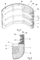
- Fig. 3 shows a panel with tubes 17a sloping downwards and outwards and protruding for a certain segment inside the area of the furnace above the liquid bath 12.
- the end of the cooling tubes 17a protrudes inside the area of the furnace to a value of "m”, from the outer wall 20, by about 450 ⁇ 600 mm, with a distance "n” from the inner edge of the lower shell 11 of about 100 ⁇ 150 mm.
- the height "1" of the end of the cooling tube 17a with respect to the upper level of the liquid bath 12 has a value of about 400 ⁇ 500 mm.
- the cooling tubes 17a sloping and protruding towards the inside of the working area of the furnace, allow a layer of slag 22a to form which covers the shoulder 11a of the lower shell 11 in the zone where there is the greatest risk of wear and where the thermo-mechanical stresses are highest due to the high temperatures and the chemical reactions.
- the protruding part of the tubes 17a is sprayed with refractory material so that the refractory, cooling down as it comes into contact with the tubes 17a, solidifies and creates a protective and insulating layer which is then incorporated into the slag 22a which is progressively deposited during the melting cycle onto the tubes 17a.
- the water is discharged far from the furnace. Moreover, to farther facilitate the discharge of the water, the water is supplied to the tubes 17, 17a by suction and not under pressure.
- the inner layer 19c is supplied with water independently of the other two layers 19a and 19b so that, even in the event of a breakage, it can continue to carry out its function of forming the layer of protective and insulating slag, and the furnace can continue to function.
- the inner layer 19c is supplied independently while the other two layers 19a and 19b are supplied in series; in Fig. 6b the three layers 19a, 19b and 19c are all supplied independently.
- the layers 19a, 19b and 19c are connected to each other by means of hooks 23 for example made of hollow tubes so as to allow the cooling liquid to circulate; they are not shown in detail here.
- the tubes 17 On their surface the tubes 17 have means which facilitate and consolidate the attachment of the slag 22. These means may consist of parallelepiped protrusions 24 distributed on the periphery of the tube 17 and arranged in alignment (Fig. 7a) or like a chess board (Fig. 7b).
- These means may also consist of longitudinal ridges 124 which run continuously along the whole length of the tube 17; they may be circular in section, as in Fig. 7c, square, hexagonal or any other desired section.
- the means may consist of hooks 224 which extend in a transverse direction with respect to the relative tube 17.
- the tubes 17 used, according to the invention have no welds and may be of different shapes, not only circular; for example they may be oval or similar, or they may contain filling means inside which limit the area of transit of the cooling liquid, and concentrate it in the front area which faces the inside of the furnace.
- Figs. 4 and 5 the device 10 is applied to the roof 18 of the furnace which has a hole 18a substantially at the centre, through which the electrode 25 is inserted.
- the device 10 includes, as above, an outer layer 19a, an intermediate layer 19b and an inner layer 19c facing the working area of the furnace.
- the tubes 17 of the layers 19a, 19b and 19c may be arranged along concentric circumferences with respect to the roof 18 (Fig. 4), or radially (Fig. 5). In Figs. 4 and 5 it is possible to see the connecting hooks 26 by means of which the layers 19a, 19b and 19c are constrained together.
- the tubes 17 are associated with manifolds 27, 28 for the inlet-outlet of the cooling liquid.
- the spaces between the tubes 17 increase in size as they go towards the inner part of the furnace in order to facilitate the attachment of the slag 22 so as to create a protective and insulating layer for the inner layers.
Abstract
Description
- Fig. 1
- shows in diagram form a section plane of a furnace equipped with a cooling device according to the invention;
- Fig. 2
- is a part view of the lower part of a furnace equipped with the cooling device as shown in Fig. 1;
- Fig. 3
- shows a variant of Fig. 2;
- Fig. 4
- shows a section of the roof of a furnace equipped with a cooling device according to the invention;
- Fig. 5
- shows a variant of Fig. 4;
- Figs. 6a and 6b
- show in diagram form two configurations of the water supply to the tubes;
- Figs. 7a-7d
- show possible solutions to achieve the hooks to attach slag on the profile of the tubes.
Claims (18)
- Electric arc furnace comprising a lower shell (11) containing a bath of liquid metal (12) and an overhead upper shell defined by a plurality of panels (16) consisting of cooling tubes (17), the upper shell being covered by the roof (18), the lower shell (11) including a containing element (15) made of metal on the outer part, the internal refractory including an upper edge (11a) located approximately at the upper line of the layer of slag (14) present above the bath of molten metal (12), characterised in that each panel (16) includes at least three layers of cooling tubes, an outer layer (19a), an intermediate layer (19b) and an inner layer (19c), the layers of cooling tubes developing vertically along the vertical sidewall of said overhead upper shell above the refractory edge (11a) of the lower shell (11), in that the vertical distance between the cooling tubes (17) of said intermediate layer (19b) is greater than the vertical distance between the cooling tubes (17) of said outer layer (19a) and in that the vertical distance between the cooling tubes (17) of said inner layer (19c) is greater than the vertical distance between the cooling tubes (17) of said intermediate layer (19b) so as to define fissures and spaces of a progressively increasing size from the outside of the furnace towards the inside thereof whereon the slag attaches itself.
- Electric arc furnace as in Claim 1, in which, in cooperation with the upper edge (11a) of the lower shell (11), there is a panel of cooling tubes (17a) cooperating with the upper level of the slag (14).
- Electric arc furnace as in Claim 1 or 2, which further comprises an outer layer (19a), an intermediate layer (19b) and at least an inner layer (19c) associated with the roof (18) of the furnace, with a distance between the tubes (17) of each layer (19a, 19b, 19c) progressively greater from the outside of the furnace towards the inside.
- Electric arc furnace as in Claim 2, in which the cooling tubes (17a) cooperating with the upper edge (11a) of the lower shell (11) slope downwards and towards the outside of the furnace.
- Electric arc furnace as in Claim 4, in which the front end of the tubes (17a) protrudes towards the inside of the furnace for a distance of at least 100 mm with respect to the inner edge of the lower shell (11).
- Electric arc furnace as in Claims 4 or 5, in which the front end of the tubes (17a) is arranged at a height of at least 400 mm with respect to the upper level of the bath of melting metal (12).
- Electric arc furnace as in any claim hereinbefore, in which the portion of the tubes (17a) protruding inside the working area of the furnace is covered by refractory material sprayed at the start of the melting cycle.
- Electric arc furnace as in any claim hereinbefore, in which for each row of tubes (17) of the inner layer (19c) there are two rows of tubes (17) of the intermediate layer (19b).
- Electric arc furnace as in any claim hereinbefore, in which for each row of tubes (17) of the intermediate layer (19b) there are two rows of tubes (17) of the outer layer (19a).
- Electric arc furnace as in any claim hereinbefore, in which the cooling tubes (17) of the outer layer (19a) are in close proximity to each other and separated from each other by fissures (21).
- Electric arc furnace as in any claim hereinbefore, in which the outer layer (19a) is covered on the outside by a metallic wall (20).
- Electric arc furnace as in any claim hereinbefore, in which the inner layer (19c) is at least partly sloping with respect to the intermediate layer (19b) and outer layer (19a).
- Electric arc furnace as in any claim hereinbefore, in which at least the inner layer (19c) is supplied with cooling liquid independently of the other two layers (19a, 19b).
- Electric arc furnace as in any claim hereinbefore, in which the intermediate layer (19b) and the outer layer (19a) are supplied in series.
- Electric arc furnace as in any claim hereinbefore, in which at least the tubes (17a) cooperating with the upper edge (11a) of the lower shell (11) are supplied with cooling liquid by suction.
- Electric arc furnace as in any claim hereinbefore, in which the layers (19a, 19b, 19c) are connected to each other by metallic hooks (26).
- Electric arc furnace as in any claim hereinbefore, in which at least the tubes (17) of the inner layer (19c) have surface means to attach the slag distributed lengthwise in a discontinuous manner (24), lengthwise in a continuous manner (124) or transversely (224).
- Electric arc furnace as in any claim hereinbefore, in which the tubes (17) at least of the inner layer (19c) are obtained from a hot-bent continuous tube.
Applications Claiming Priority (3)
| Application Number | Priority Date | Filing Date | Title |
|---|---|---|---|
| IT1997GO000018A IT1304334B1 (en) | 1997-09-10 | 1997-09-10 | PANEL COOLING DEVICE FOR ELECTRIC ARC OVEN |
| ITGO970018 | 1997-09-10 | ||
| PCT/IB1998/001371 WO1999013281A1 (en) | 1997-09-10 | 1998-09-03 | Cooling device with panels for electric arc furnace |
Publications (2)
| Publication Number | Publication Date |
|---|---|
| EP1019664A1 EP1019664A1 (en) | 2000-07-19 |
| EP1019664B1 true EP1019664B1 (en) | 2001-12-12 |
Family
ID=11355470
Family Applications (1)
| Application Number | Title | Priority Date | Filing Date |
|---|---|---|---|
| EP98939788A Expired - Lifetime EP1019664B1 (en) | 1997-09-10 | 1998-09-03 | Electric arc furnace with a cooling device with panels |
Country Status (8)
| Country | Link |
|---|---|
| US (1) | US6249538B1 (en) |
| EP (1) | EP1019664B1 (en) |
| AT (1) | ATE210810T1 (en) |
| AU (1) | AU8818798A (en) |
| DE (1) | DE69802953T2 (en) |
| ES (1) | ES2168786T3 (en) |
| IT (1) | IT1304334B1 (en) |
| WO (1) | WO1999013281A1 (en) |
Families Citing this family (7)
| Publication number | Priority date | Publication date | Assignee | Title |
|---|---|---|---|---|
| US6535522B1 (en) * | 1997-10-01 | 2003-03-18 | Globespanvirata, Inc. | Multiple protocol interface and method for use in a communications system |
| EP1469085A1 (en) * | 2003-04-14 | 2004-10-20 | Paul Wurth S.A. | Cooling plate for a metallurgical vessel |
| KR101159968B1 (en) * | 2010-04-29 | 2012-06-25 | 현대제철 주식회사 | Cooling Panel of Electric Furnace |
| CN105579803B (en) | 2013-12-20 | 2018-06-22 | 魁北克9282-3087公司(加钛顾问公司) | metallurgical furnace |
| WO2016010919A1 (en) * | 2014-07-16 | 2016-01-21 | Trapp Mark Edward | Furnace cooling panel monitoring system |
| BR102015013157B1 (en) * | 2015-06-05 | 2021-12-21 | Lumar Metals Ltda | REFRIGERATED DOUBLE PANEL FOR ELECTRIC ARC OVENS |
| CN114396627B (en) * | 2021-12-14 | 2023-09-26 | 北京建筑材料科学研究总院有限公司 | Rotary fire grate and vertical incinerator |
Family Cites Families (8)
| Publication number | Priority date | Publication date | Assignee | Title |
|---|---|---|---|---|
| US2752410A (en) * | 1955-06-20 | 1956-06-26 | Sunrod Mfg Corp | Electrical reduction furnace having means to protect the walls thereof from heat within the furnace and to utilize otherwise wasted heat |
| AT338307B (en) * | 1973-07-23 | 1977-08-25 | Voest Ag | METALLURGICAL VESSEL, IN PARTICULAR CONVERTER |
| DE2759713C2 (en) * | 1977-10-11 | 1983-10-27 | Mannesmann AG, 4000 Düsseldorf | Vessel cover for a metal melting furnace, in particular an electric arc furnace |
| DE2928964A1 (en) * | 1979-07-18 | 1981-01-29 | Lentjes Dampfkessel Ferd | Cooled door frame on steelworks furnaces - esp. open hearth furnaces, where frame contains pipes through which cooling water is circulated |
| DE2943244C2 (en) * | 1979-10-26 | 1983-01-05 | Mannesmann AG, 4000 Düsseldorf | Vessel lid for a metal melting furnace, in particular an electric arc furnace |
| NO155903C (en) * | 1985-02-07 | 1987-06-17 | Elkem As | SIDE WALL IN A METALLURGICAL MELTING Oven. |
| US5241559A (en) * | 1992-03-30 | 1993-08-31 | Emc International, Inc. | Electric arc furnace roof |
| IT1288850B1 (en) * | 1996-02-14 | 1998-09-25 | Danieli Off Mecc | COOLING DEVICE WITH SIDE PANELS FOR ELECTRIC OVEN |
-
1997
- 1997-09-10 IT IT1997GO000018A patent/IT1304334B1/en active
-
1998
- 1998-09-03 AT AT98939788T patent/ATE210810T1/en active
- 1998-09-03 EP EP98939788A patent/EP1019664B1/en not_active Expired - Lifetime
- 1998-09-03 WO PCT/IB1998/001371 patent/WO1999013281A1/en active IP Right Grant
- 1998-09-03 DE DE69802953T patent/DE69802953T2/en not_active Expired - Lifetime
- 1998-09-03 AU AU88187/98A patent/AU8818798A/en not_active Abandoned
- 1998-09-03 ES ES98939788T patent/ES2168786T3/en not_active Expired - Lifetime
- 1998-09-03 US US09/508,273 patent/US6249538B1/en not_active Expired - Lifetime
Also Published As
| Publication number | Publication date |
|---|---|
| ES2168786T3 (en) | 2002-06-16 |
| US6249538B1 (en) | 2001-06-19 |
| IT1304334B1 (en) | 2001-03-15 |
| EP1019664A1 (en) | 2000-07-19 |
| AU8818798A (en) | 1999-03-29 |
| DE69802953T2 (en) | 2002-06-06 |
| DE69802953D1 (en) | 2002-01-24 |
| ATE210810T1 (en) | 2001-12-15 |
| WO1999013281A1 (en) | 1999-03-18 |
| ITGO970018A1 (en) | 1999-03-10 |
Similar Documents
| Publication | Publication Date | Title |
|---|---|---|
| US5613994A (en) | Electric furnace for melting glass | |
| KR100367467B1 (en) | Water-cooling panel for furnace wall and furnace cover of arc furnace | |
| US4637034A (en) | Cooling panel for electric arc furnace | |
| EP1019664B1 (en) | Electric arc furnace with a cooling device with panels | |
| MX2011010820A (en) | Cooling plate for a metallurgical furnace. | |
| EP1629243B1 (en) | Device for improved slag retention in water cooled furnace elements | |
| ES2296731T3 (en) | HEAT EXCHANGE PIPE WITH EXTRUDED FINS. | |
| EP0790473B1 (en) | Cooling device with panels for electric arc furnaces | |
| CN101040161B (en) | Metallurgical furnace | |
| US4435814A (en) | Electric furnace having liquid-cooled vessel walls | |
| MXPA97001174A (en) | Cooling device for arc electr oven | |
| AU738253B2 (en) | Tapping launder for a molten iron | |
| MXPA97001175A (en) | Cooling device for arcoelectr ovens | |
| CN220541699U (en) | Cooling device for an electric furnace or the like and electric furnace | |
| EP0790474A1 (en) | Cooled roof for electric arc furnaces and for ladle furnaces | |
| JPS5916914A (en) | Cooling construction of furnace wall of blast furnace constituted of two layers cooling zone | |
| GB1598370A (en) | Refractory linings for furnaces | |
| JP2001049316A (en) | Stave for shaft furnace type metallurgical furnace and disposing structure thereof | |
| JPS61266315A (en) | Glass melting tank furnace | |
| SU998508A1 (en) | Blast furnace cooler | |
| JPH06158131A (en) | Device for cooling side wall in furnace bottom part of blast furnace | |
| RU2235134C1 (en) | Plate type cooler for metallurgical furnaces | |
| RU2231725C2 (en) | A cool smelting hearth | |
| RU2199066C2 (en) | Cold crucible | |
| KR100456036B1 (en) | Cooling panel for a shaft furnace |
Legal Events
| Date | Code | Title | Description |
|---|---|---|---|
| PUAI | Public reference made under article 153(3) epc to a published international application that has entered the european phase |
Free format text: ORIGINAL CODE: 0009012 |
|
| 17P | Request for examination filed |
Effective date: 20000313 |
|
| AK | Designated contracting states |
Kind code of ref document: A1 Designated state(s): AT BE CH DE ES FI FR GB GR IT LI NL SE |
|
| AX | Request for extension of the european patent |
Free format text: SI PAYMENT 20000313 |
|
| GRAG | Despatch of communication of intention to grant |
Free format text: ORIGINAL CODE: EPIDOS AGRA |
|
| GRAG | Despatch of communication of intention to grant |
Free format text: ORIGINAL CODE: EPIDOS AGRA |
|
| GRAG | Despatch of communication of intention to grant |
Free format text: ORIGINAL CODE: EPIDOS AGRA |
|
| GRAH | Despatch of communication of intention to grant a patent |
Free format text: ORIGINAL CODE: EPIDOS IGRA |
|
| 17Q | First examination report despatched |
Effective date: 20010122 |
|
| GRAG | Despatch of communication of intention to grant |
Free format text: ORIGINAL CODE: EPIDOS AGRA |
|
| GRAH | Despatch of communication of intention to grant a patent |
Free format text: ORIGINAL CODE: EPIDOS IGRA |
|
| RTI1 | Title (correction) |
Free format text: ELECTRIC ARC FURNACE WITH A COOLING DEVICE WITH PANELS |
|
| GRAH | Despatch of communication of intention to grant a patent |
Free format text: ORIGINAL CODE: EPIDOS IGRA |
|
| GRAA | (expected) grant |
Free format text: ORIGINAL CODE: 0009210 |
|
| AK | Designated contracting states |
Kind code of ref document: B1 Designated state(s): AT BE CH DE ES FI FR GB GR IT LI NL SE |
|
| AX | Request for extension of the european patent |
Free format text: SI PAYMENT 20000313 |
|
| PG25 | Lapsed in a contracting state [announced via postgrant information from national office to epo] |
Ref country code: NL Free format text: LAPSE BECAUSE OF FAILURE TO SUBMIT A TRANSLATION OF THE DESCRIPTION OR TO PAY THE FEE WITHIN THE PRESCRIBED TIME-LIMIT Effective date: 20011212 Ref country code: LI Free format text: LAPSE BECAUSE OF FAILURE TO SUBMIT A TRANSLATION OF THE DESCRIPTION OR TO PAY THE FEE WITHIN THE PRESCRIBED TIME-LIMIT Effective date: 20011212 Ref country code: GR Free format text: LAPSE BECAUSE OF FAILURE TO SUBMIT A TRANSLATION OF THE DESCRIPTION OR TO PAY THE FEE WITHIN THE PRESCRIBED TIME-LIMIT Effective date: 20011212 Ref country code: FR Free format text: LAPSE BECAUSE OF FAILURE TO SUBMIT A TRANSLATION OF THE DESCRIPTION OR TO PAY THE FEE WITHIN THE PRESCRIBED TIME-LIMIT Effective date: 20011212 Ref country code: FI Free format text: LAPSE BECAUSE OF FAILURE TO SUBMIT A TRANSLATION OF THE DESCRIPTION OR TO PAY THE FEE WITHIN THE PRESCRIBED TIME-LIMIT Effective date: 20011212 Ref country code: CH Free format text: LAPSE BECAUSE OF FAILURE TO SUBMIT A TRANSLATION OF THE DESCRIPTION OR TO PAY THE FEE WITHIN THE PRESCRIBED TIME-LIMIT Effective date: 20011212 Ref country code: BE Free format text: LAPSE BECAUSE OF FAILURE TO SUBMIT A TRANSLATION OF THE DESCRIPTION OR TO PAY THE FEE WITHIN THE PRESCRIBED TIME-LIMIT Effective date: 20011212 |
|
| REF | Corresponds to: |
Ref document number: 210810 Country of ref document: AT Date of ref document: 20011215 Kind code of ref document: T |
|
| REG | Reference to a national code |
Ref country code: CH Ref legal event code: EP |
|
| REG | Reference to a national code |
Ref country code: GB Ref legal event code: IF02 |
|
| REF | Corresponds to: |
Ref document number: 69802953 Country of ref document: DE Date of ref document: 20020124 |
|
| PG25 | Lapsed in a contracting state [announced via postgrant information from national office to epo] |
Ref country code: SE Free format text: LAPSE BECAUSE OF FAILURE TO SUBMIT A TRANSLATION OF THE DESCRIPTION OR TO PAY THE FEE WITHIN THE PRESCRIBED TIME-LIMIT Effective date: 20020312 |
|
| NLV1 | Nl: lapsed or annulled due to failure to fulfill the requirements of art. 29p and 29m of the patents act | ||
| REG | Reference to a national code |
Ref country code: CH Ref legal event code: PL |
|
| REG | Reference to a national code |
Ref country code: ES Ref legal event code: FG2A Ref document number: 2168786 Country of ref document: ES Kind code of ref document: T3 |
|
| PG25 | Lapsed in a contracting state [announced via postgrant information from national office to epo] |
Ref country code: GB Free format text: LAPSE BECAUSE OF NON-PAYMENT OF DUE FEES Effective date: 20020903 |
|
| EN | Fr: translation not filed | ||
| PLBE | No opposition filed within time limit |
Free format text: ORIGINAL CODE: 0009261 |
|
| STAA | Information on the status of an ep patent application or granted ep patent |
Free format text: STATUS: NO OPPOSITION FILED WITHIN TIME LIMIT |
|
| 26N | No opposition filed | ||
| GBPC | Gb: european patent ceased through non-payment of renewal fee |
Effective date: 20020903 |
|
| NLV1 | Nl: lapsed or annulled due to failure to fulfill the requirements of art. 29p and 29m of the patents act | ||
| PGFP | Annual fee paid to national office [announced via postgrant information from national office to epo] |
Ref country code: ES Payment date: 20130906 Year of fee payment: 16 |
|
| PGFP | Annual fee paid to national office [announced via postgrant information from national office to epo] |
Ref country code: DE Payment date: 20140822 Year of fee payment: 17 |
|
| PGFP | Annual fee paid to national office [announced via postgrant information from national office to epo] |
Ref country code: AT Payment date: 20140825 Year of fee payment: 17 |
|
| PGFP | Annual fee paid to national office [announced via postgrant information from national office to epo] |
Ref country code: IT Payment date: 20140826 Year of fee payment: 17 |
|
| REG | Reference to a national code |
Ref country code: ES Ref legal event code: FD2A Effective date: 20151027 |
|
| PG25 | Lapsed in a contracting state [announced via postgrant information from national office to epo] |
Ref country code: ES Free format text: LAPSE BECAUSE OF NON-PAYMENT OF DUE FEES Effective date: 20140904 |
|
| REG | Reference to a national code |
Ref country code: DE Ref legal event code: R119 Ref document number: 69802953 Country of ref document: DE |
|
| PG25 | Lapsed in a contracting state [announced via postgrant information from national office to epo] |
Ref country code: IT Free format text: LAPSE BECAUSE OF NON-PAYMENT OF DUE FEES Effective date: 20150903 |
|
| REG | Reference to a national code |
Ref country code: AT Ref legal event code: MM01 Ref document number: 210810 Country of ref document: AT Kind code of ref document: T Effective date: 20150903 |
|
| PG25 | Lapsed in a contracting state [announced via postgrant information from national office to epo] |
Ref country code: DE Free format text: LAPSE BECAUSE OF NON-PAYMENT OF DUE FEES Effective date: 20160401 |
|
| PG25 | Lapsed in a contracting state [announced via postgrant information from national office to epo] |
Ref country code: AT Free format text: LAPSE BECAUSE OF NON-PAYMENT OF DUE FEES Effective date: 20150903 |