EP1018562A1 - Device and method for opening and closing automatically the cover of a quenching tank - Google Patents
Device and method for opening and closing automatically the cover of a quenching tank Download PDFInfo
- Publication number
- EP1018562A1 EP1018562A1 EP99100284A EP99100284A EP1018562A1 EP 1018562 A1 EP1018562 A1 EP 1018562A1 EP 99100284 A EP99100284 A EP 99100284A EP 99100284 A EP99100284 A EP 99100284A EP 1018562 A1 EP1018562 A1 EP 1018562A1
- Authority
- EP
- European Patent Office
- Prior art keywords
- oven
- door
- opening
- tank
- heat treatment
- Prior art date
- Legal status (The legal status is an assumption and is not a legal conclusion. Google has not performed a legal analysis and makes no representation as to the accuracy of the status listed.)
- Withdrawn
Links
Images

Classifications
-
- F—MECHANICAL ENGINEERING; LIGHTING; HEATING; WEAPONS; BLASTING
- F27—FURNACES; KILNS; OVENS; RETORTS
- F27D—DETAILS OR ACCESSORIES OF FURNACES, KILNS, OVENS, OR RETORTS, IN SO FAR AS THEY ARE OF KINDS OCCURRING IN MORE THAN ONE KIND OF FURNACE
- F27D1/00—Casings; Linings; Walls; Roofs
- F27D1/18—Door frames; Doors, lids, removable covers
-
- C—CHEMISTRY; METALLURGY
- C21—METALLURGY OF IRON
- C21D—MODIFYING THE PHYSICAL STRUCTURE OF FERROUS METALS; GENERAL DEVICES FOR HEAT TREATMENT OF FERROUS OR NON-FERROUS METALS OR ALLOYS; MAKING METAL MALLEABLE, e.g. BY DECARBURISATION OR TEMPERING
- C21D1/00—General methods or devices for heat treatment, e.g. annealing, hardening, quenching or tempering
- C21D1/62—Quenching devices
- C21D1/63—Quenching devices for bath quenching
-
- C—CHEMISTRY; METALLURGY
- C21—METALLURGY OF IRON
- C21D—MODIFYING THE PHYSICAL STRUCTURE OF FERROUS METALS; GENERAL DEVICES FOR HEAT TREATMENT OF FERROUS OR NON-FERROUS METALS OR ALLOYS; MAKING METAL MALLEABLE, e.g. BY DECARBURISATION OR TEMPERING
- C21D9/00—Heat treatment, e.g. annealing, hardening, quenching or tempering, adapted for particular articles; Furnaces therefor
- C21D9/0062—Heat-treating apparatus with a cooling or quenching zone
-
- F—MECHANICAL ENGINEERING; LIGHTING; HEATING; WEAPONS; BLASTING
- F27—FURNACES; KILNS; OVENS; RETORTS
- F27B—FURNACES, KILNS, OVENS, OR RETORTS IN GENERAL; OPEN SINTERING OR LIKE APPARATUS
- F27B17/00—Furnaces of a kind not covered by any preceding group
- F27B17/0016—Chamber type furnaces
-
- F—MECHANICAL ENGINEERING; LIGHTING; HEATING; WEAPONS; BLASTING
- F27—FURNACES; KILNS; OVENS; RETORTS
- F27D—DETAILS OR ACCESSORIES OF FURNACES, KILNS, OVENS, OR RETORTS, IN SO FAR AS THEY ARE OF KINDS OCCURRING IN MORE THAN ONE KIND OF FURNACE
- F27D3/00—Charging; Discharging; Manipulation of charge
-
- F—MECHANICAL ENGINEERING; LIGHTING; HEATING; WEAPONS; BLASTING
- F27—FURNACES; KILNS; OVENS; RETORTS
- F27D—DETAILS OR ACCESSORIES OF FURNACES, KILNS, OVENS, OR RETORTS, IN SO FAR AS THEY ARE OF KINDS OCCURRING IN MORE THAN ONE KIND OF FURNACE
- F27D1/00—Casings; Linings; Walls; Roofs
- F27D1/18—Door frames; Doors, lids, removable covers
- F27D1/1808—Removable covers
- F27D2001/1825—Means for moving the cover
- F27D2001/1841—Means for moving the cover comprising means for rotating or moving the cover in a horizontal or quasi horizontal plane
-
- F—MECHANICAL ENGINEERING; LIGHTING; HEATING; WEAPONS; BLASTING
- F27—FURNACES; KILNS; OVENS; RETORTS
- F27D—DETAILS OR ACCESSORIES OF FURNACES, KILNS, OVENS, OR RETORTS, IN SO FAR AS THEY ARE OF KINDS OCCURRING IN MORE THAN ONE KIND OF FURNACE
- F27D3/00—Charging; Discharging; Manipulation of charge
- F27D2003/0034—Means for moving, conveying, transporting the charge in the furnace or in the charging facilities
- F27D2003/0075—Charging or discharging vertically, e.g. through a bottom opening
-
- F—MECHANICAL ENGINEERING; LIGHTING; HEATING; WEAPONS; BLASTING
- F27—FURNACES; KILNS; OVENS; RETORTS
- F27D—DETAILS OR ACCESSORIES OF FURNACES, KILNS, OVENS, OR RETORTS, IN SO FAR AS THEY ARE OF KINDS OCCURRING IN MORE THAN ONE KIND OF FURNACE
- F27D5/00—Supports, screens, or the like for the charge within the furnace
Abstract
Description
L'invention concerne le domaine technique général des installations de traitement thermique de charges quelconques, et en particulier de charges formées de pièces métalliques et destinées à subir un traitement thermique dans un four, puis à être traitées, par exemple par refroidissement, dans un bac de trempe contenant un bain liquide.The invention relates to the general technical field of heat treatment of any charges, and in particular of charges formed of metal parts and intended to undergo a heat treatment in an oven, then to be treated, for example by cooling, in a quench tank containing a liquid bath.
La présente invention concerne une installation de traitement thermique d'une charge à traiter comportant au moins un four ayant une ouverture, et au moins un bac de trempe ayant également une ouverture susceptible d'être associée à une porte, les ouvertures du four et du bac étant agencées de telle manière que, par déplacement relatif du four et/ou du bac, leurs ouvertures respectives viennent sensiblement en regard l'une par rapport à l'autre en vue d'assurer le transfert de la charge du four vers le bac ou inversement.The present invention relates to a thermal treatment installation a load to be treated comprising at least one oven having an opening, and at least one quenching tank also having an opening capable of being associated with a door, the oven and tray openings being arranged such that, by relative movement of the oven and / or the tray, their respective openings come substantially opposite one with respect to the other to transfer the load from the oven to the tank or Conversely.
La présente invention concerne également un procédé de traitement thermique d'une charge mettant en oeuvre au moins un four de traitement ayant une ouverture, et au moins un bac de trempe ayant également une ouverture susceptible d'être associée à une porte, lesdites ouvertures étant agencées entre elles pour que, par déplacement relatif du four et/ou du bac, leurs ouvertures respectives viennent sensiblement en regard l'une par rapport à l'autre en vue d'assurer le transfert de la charge du four vers le bac ou inversement.The present invention also relates to a method of treatment thermal of a load using at least one treatment furnace having an opening, and at least one quench tank also having a opening capable of being associated with a door, said openings being arranged between them so that, by relative movement of the oven and / or the tray, their respective openings come substantially opposite one by to the other in order to transfer the load from the oven to the bac or vice versa.
Des installations de traitement thermique du genre mentionné ci-dessus sont déjà connues, et par exemple du document EP-A-0 296 102.Heat treatment plants of the kind mentioned above are already known, and for example from document EP-A-0 296 102.
De telles installations comportent au moins un four ayant une ouverture dirigée vers le bas et au moins un bac de trempe ayant une ouverture dirigée vers le haut, de telle sorte que le four et le bac peuvent être amenés en position superposée par mouvement relatif de l'un par rapport à l'autre, afin que l'ouverture du four puisse venir en regard de l'ouverture du bac en vue d'assurer le transfert d'une charge du four vers le bac et/ou inversement.Such installations include at least one oven having an opening directed downwards and at least one quenching tank having a directed opening upwards, so that the oven and the pan can be brought in position superimposed by relative movement of one relative to the other, so that the opening of the oven can come opposite the opening of the tank in view ensure the transfer of a load from the oven to the tank and / or vice versa.
Il est également connu, de manière générale, de monter une porte ou un couvercle sur le bac de trempe afin de pouvoir fermer l'ouverture du bac lorsque le four n'est pas au droit de l'ouverture en vue de protéger le liquide contenu dans le bac de toute pollution externe. A l'inverse, la présence d'une porte permet également d'éviter toute pollution du milieu externe par le liquide du bac.It is also generally known to mount a door or a cover on the quenching tank in order to close the opening of the tank when the oven is not in line with the opening to protect the liquid contained in the bin of any external pollution. Conversely, the presence of a door also avoids any pollution of the external environment by the liquid Tray.
Dans les installations connues à ce jour, les portes des bacs de trempe sont, de manière classique, associées à une commande hydraulique ou pneumatique, incluant un vérin et une centrale de commande comprenant un microprocesseur en vue de commander l'ouverture ou la fermeture automatique de ladite porte. L'ensemble de commande est complété par une série de capteurs appropriés destinés à fournir les signaux de commande de déplacement du vérin induisant l'ouverture ou la fermeture de la porte.In the installations known to date, the doors of the quenching tanks are, conventionally, associated with a hydraulic control or pneumatic, including a cylinder and a control unit comprising a microprocessor for controlling opening or closing automatic said door. The control set is completed by a series of suitable sensors for supplying control signals displacement of the cylinder inducing the opening or closing of the door.
Dans les dispositifs connus, la porte du bac se déplace en translation au-dessus de l'ouverture du bac, et parallèlement au plan de celle-ci, la porte étant associée à un joint O-ring destiné à assurer l'étanchéité complète du bac vis-à-vis de l'extérieur en position de fermeture. Un système de cames et de glissières assure en fin de course une compression du joint O-ring lui permettant d'assurer pleinement sa fonction d'étanchéité.In known devices, the bin door moves in translation above the opening of the container, and parallel to the plane thereof, the door being associated with an O-ring seal intended to ensure complete sealing of the container vis-à-vis the outside in the closed position. A system of cams and of slides ensures end-of-travel compression of the O-ring seal to fully ensure its sealing function.
On connaít également des installations de traitement thermique comportant des portes basculantes commandées également par une série d'actionneurs mécaniques, du genre vérin hydraulique ou analogue.We also know heat treatment facilities comprising overhead doors also controlled by a series mechanical actuators, such as hydraulic cylinders or the like.
Les dispositifs connus de l'art antérieur, s'ils permettent effectivement d'obtenir une certaine automatisation de l'opération d'ouverture et de fermeture de la porte du bac de trempe, souffrent néanmoins de certains inconvénients.The devices known from the prior art, if they actually allow obtain some automation of the opening operation and closure of the quenching tank door, nevertheless suffer from certain disadvantages.
En premier lieu, ils s'avèrent d'un coût de fabrication relativement élevé puisqu'ils mettent en oeuvre une technologie relativement élaborée, impliquant un grand nombre de pièces qui, de surcroít, sont d'une finition relativement exigeante. En second lieu, le recours à une série d'actionneurs, du type vérin hydraulique, nécessite la présente d'une centrale de commande et de divers organes de commande de la gestion du déplacement, ce qui, au total, s'avère former un ensemble relativement complexe, source de pannes et de dysfonctionnements notables. La relative complexité de ces systèmes de commandes implique en outre des temps et durées de réparation conséquents, susceptibles de bloquer l'ensemble de la chaíne de traitement thermique, ce qui, bien évidemment, constitue un autre inconvénient sur le plan industriel. En dernier lieu, les dispositifs connus jusqu'à présent nécessitent l'usinage d'une gorge dans la porte de fermeture pour loger le joint O-ring destiné à réaliser l'étanchéité entre la porte et le bac de trempe. L'opération d'usinage représente bien évidemment un coût supplémentaire pour l'installation de traitement thermique.First, they turn out to be of relatively high manufacturing cost since they implement a relatively sophisticated technology, involving a large number of parts which, moreover, are of a relatively finished demanding. Second, the use of a series of actuators, of the jack type hydraulic, requires the presence of a control unit and various displacement management controls, which, in total, turns out form a relatively complex whole, source of breakdowns and notable malfunctions. The relative complexity of these orders also involve repair times and durations consequent, likely to block the entire processing chain thermal, which is obviously another drawback in terms of industrial. Finally, the devices known so far require machining a groove in the closing door to accommodate the O-ring seal designed to seal between the door and the quench tank. The operation machining obviously represents an additional cost for the heat treatment installation.
La présente invention a, en conséquence, pour objet de porter remède à l'ensemble des divers inconvénients énumérés précédemment et vise à proposer une nouvelle installation et un nouveau procédé de traitement thermique de conception et de fonctionnement particulièrement simple et éprouvé.The object of the present invention is therefore to provide a remedy to all of the various drawbacks listed above and aims to propose a new installation and a new treatment process thermal design and particularly simple operation and proven.
Un autre objet de l'invention vise à proposer une nouvelle installation et un nouveau procédé de traitement thermique ne nécessitant qu'un apport limité de source énergétique externe pour son fonctionnement.Another object of the invention aims to propose a new installation and a new heat treatment process requiring only a contribution limited external energy source for its operation.
Un autre objet de l'invention vise à proposer une nouvelle installation et un nouveau procédé de traitement thermique mettant en oeuvre un système d'accrochage/décrochage de conception particulièrement simple et robuste.Another object of the invention aims to propose a new installation and a new heat treatment process using a system particularly simple and robust hooking / unhooking design.
Un autre objet de l'invention vise à proposer une nouvelle installation et un nouveau procédé de traitement thermique dont la sécurité de fonctionnement est renforcée.Another object of the invention aims to propose a new installation and a new heat treatment process, the safety of functioning is strengthened.
Les objets assignés à l'invention sont atteints à l'aide d'une installation de traitement thermique d'une charge à traiter comportant au moins un four ayant une ouverture, et au moins un bac de trempe ayant également une ouverture susceptible d'être associée à une porte, lesdites ouvertures étant agencées de telle sorte que, par déplacement relatif du four et/ou du bac de trempe, leurs ouvertures respectives viennent sensiblement et en regard l'une par rapport à l'autre, en vue d'assurer le transfert de la charge du four vers le bac de trempe ou inversement, caractérisée en ce qu'elle comprend :
- des moyens d'accrochage/décrochage disposés en partie sur le four et en partie sur la porte et destinés à occuper d'une part une position d'accrochage dans laquelle ils coopèrent pour accrocher ensemble le four et la porte, et d'autre part une position de décrochage dans laquelle le four et la porte sont décrochés l'une de l'autre, lesdits moyens étant prévus pour permettre, en position d'accrochage, le déplacement de la porte de sa position d'ouverture vers sa position de fermeture et/ou inversement lors du déplacement relatif du four et du bac de trempe.
- hooking / unhooking means arranged partly on the oven and partly on the door and intended to occupy on the one hand a hooking position in which they cooperate to hang the oven and the door together, and on the other hand a stall position in which the oven and the door are detached from each other, said means being provided to allow, in the hanging position, the movement of the door from its open position to its closed position and / or vice versa during the relative movement of the oven and the quench tank.
Les objets assignés à l'invention sont également atteints à l'aide d'un procédé de traitement thermique d'une charge mettant en oeuvre au moins un four de traitement ayant une ouverture vers le bas et au moins un bac de trempe ayant une ouverture vers le haut susceptible d'être associée à une porte pour que, par déplacement relatif du four et/ou du bac, leurs ouvertures respectives viennent sensiblement et en regard l'une par rapport à l'autre, en vue d'assurer le transfert de la charge du four vers le bac ou inversement, caractérisé en ce qu'il consiste :
- à assurer le déplacement relatif du four et du bac,
- et à utiliser l'énergie résultant de ce déplacement relatif pour assurer le déplacement de la porte.
- to ensure the relative movement of the oven and the tank,
- and to use the energy resulting from this relative displacement to ensure the displacement of the door.
D'autres détails et avantages de l'invention seront décrits de manière détaillée à la lumière de la description et des exemples illustratifs qui suivent ci-après, donnés uniquement à titre d'exemples non limitatifs dans lesquels :
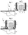
- la figure 1 montre, selon une vue partielle en coupe longitudinale transversale, une installation de traitement thermique conforme à l'invention dans laquelle la porte du bac est fermée et le four est situé hors du bac.
- la figure 2 montre, selon une vue en coupe partielle longitudinale, une installation de traitement thermique conforme à l'invention dans laquelle le four est au-dessus du bac dont la porte est ouverte.
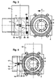
- la figure 3 illustre, selon une vue de dessus, une installation de traitement thermique conforme à l'invention dont le bac et le four sont en position identique à celle montrée à la figure 1.
- la figure 4 montre, selon une vue de dessus, une installation de traitement thermique conforme à l'invention, et dont le bac et le four sont dans une position identique à celle illustrée à la figure 2.
- la figure 5 illustre, selon une vue en coupe transversale partielle, un détail de réalisation de la porte du bac.
- la figure 6 illustre, selon une vue en coupe partielle, un détail de réalisation des moyens d'accrochage/décrochage conforme à l'invention.
- FIG. 1 shows, in a partial view in longitudinal transverse section, a thermal treatment installation according to the invention in which the door of the tank is closed and the oven is located outside the tank.
- Figure 2 shows, in a longitudinal partial sectional view, a thermal treatment installation according to the invention in which the oven is above the tray whose door is open.
- FIG. 3 illustrates, from a top view, a thermal treatment installation according to the invention, the tank and the oven are in the same position as that shown in FIG. 1.
- FIG. 4 shows, according to a top view, a thermal treatment installation according to the invention, and of which the tank and the oven are in a position identical to that illustrated in FIG. 2.
- Figure 5 illustrates, in a partial cross sectional view, a detail of the door of the tray.
- Figure 6 illustrates, in a partial sectional view, a detail of the attachment / detachment means according to the invention.
Les figures 1 à 4 montrent une installation de traitement thermique 1
conforme à l'invention. Cette installation comporte, de manière classique, au
moins un four 2, du type à cloche, et présentant une ouverture 3
avantageusement située à la partie inférieure du four pour permettre
l'introduction, par exemple par déplacement vertical, d'une charge 4,
supportée éventuellement par un plateau support 5 et destinée à subir un
traitement thermique dans le four 2.Figures 1 to 4 show a
La charge 4 peut être formée par un ensemble de pièces quelconques,
par exemple de pièces métalliques issues d'un processus de fabrication
industriel quelconque devant subir un traitement thermique, par exemple de
nettoyage ou autre. The
De manière également connue, le four 2 est pourvu intérieurement d'une
enceinte étanche 6 associée à des moyens de chauffage (non représentés aux
figures), du genre rampes de résistance électrique, ledit four pouvant être
éventuellement fermé par une pièce de fermeture (non représentée aux
figures) pendant certaines opérations de traitement.In a manner also known, the
Tel que montré aux figures 1 et 2, la partie inférieure de l'enceinte 6
peut comporter une série de supports 8 destinés à porter le plateau 5,
notamment entre la ou les opérations de traitement, lorsque le four est
ouvert.As shown in Figures 1 and 2, the lower part of the
L'installation de traitement thermique 1 comporte également, de
manière classique, un ensemble de moyens de chargement et de
déchargement (non représentés aux figures) tel que des bras et/ou robots
manipulateurs, destinés à assurer la préhension puis l'introduction ou
l'extraction de la charge 4 dans ou hors du four 2.The
De manière également connue, l'installation de traitement thermique 1
conforme à l'invention comprend une série de moyens de guidage et de
support, formés par exemple de rails ou portiques, et dont la fonction est de
permettre le support et le déplacement des fours de l'installation.In a manner also known, the
Tel qu'illustrée aux figures 1 à 4, l'installation de traitement thermique 1
conforme à l'invention comprend également un bac de trempe 10 destiné à
contenir un liquide de traitement, du type eau, sel, huile, ou autre, dans lequel
la charge 4 est destinée à être trempée. Selon une forme préférentielle de
l'invention, le bac de trempe 10 contiendra un liquide de refroidissement en
vue de réaliser un bac de refroidissement.As illustrated in FIGS. 1 to 4, the
Tel que cela est particulièrement bien visible aux figures 1 et 2, le bac
de trempe 10 est pourvu, à sa partie supérieure, d'une ouverture 11 pour
assurer l'introduction et l'extraction de la charge 4 dans et hors dudit bac de
trempe 10.As is particularly visible in Figures 1 and 2, the
Le bac de trempe 10 peut également être équipé de moyens de
chargement/déchargement autonomes (non représentés aux figures)
permettant d'introduire et d'extraire la charge 4. Alternativement, le bac de
trempe 10 peut être chargé et déchargé à partir des moyens de
chargement/déchargement du four 2. Dans ce cas, ces moyens sont donc
communs au bac de trempe 10 et au four 2.The
Dans les exemples qui suivent, le bac de trempe 10 et le four 2 ont été
représentés, respectivement avec une ouverture 11 vers le haut, et une
ouverture 3 vers le bas, pour que, par déplacement relatif du four 2 et/ou du
bac de trempe 10, les ouvertures respectives 3 et 11 viennent sensiblement
en regard l'une par rapport à l'autre (figures 2 et 4) en vue d'assurer le
transfert de la charge 4 du four 2 vers le bac de trempe 10 ou inversement.
Néanmoins, il doit être entendu qu'au sens de l'invention, une telle disposition
des ouvertures 3 et 11 n'est que préférentielle, et que lesdites ouvertures 3,
11 peuvent être agencées d'une manière différente, respectivement dans le
four 2 et le bac de trempe 10, l'essentiel étant que lesdites ouvertures 3, 11
puissent venir en regard l'une de l'autre en vue d'assurer le transfert de la
charge 4.In the following examples, the
Le bac de trempe 10 comporte également, en association avec
l'ouverture 11, une porte 12 montée mobile sur la partie supérieure dudit bac
de trempe 10 de manière à assurer l'ouverture et la fermeture de l'ouverture
11.The
Selon l'invention, l'installation de traitement thermique 1 comporte des
moyens d'accrochage/décrochage 15 (figure 6) disposés en partie sur le four
2 et en partie sur la porte 12, lesdits moyens étant destinés à occuper d'une
part une position d'accrochage dans laquelle ils coopèrent pour accrocher
ensemble le four 2 et la porte 12 et d'autre part, une position de décrochage
dans laquelle le four 2 et la porte 12 sont décrochés l'un de l'autre, lesdits
moyens étant prévus pour permettre, en position d'accrochage, le
déplacement de la porte 12 de sa position d'ouverture vers sa position de
fermeture et/ou inversement, lors du déplacement relatif du four 2 et du bac
de trempe 10.According to the invention, the
La présence de moyens d'accrochage/décrochage 15 de ce type
permet en conséquence de profiter du mouvement relatif du four 2
relativement au bac de trempe 10 pour assurer le déplacement de la porte
12 et réaliser ainsi, selon le sens du déplacement relatif du four 2 et du bac
de trempe 10, l'ouverture ou la fermeture de ladite porte 12. Une telle
disposition présente en conséquence l'avantage déterminant de ne nécessiter
aucun recours à une source d'énergie externe, ni à aucun dispositif de
commande spécifique.The presence of hooking / unhooking means 15 of this type
therefore allows you to take advantage of the relative movement of the
Selon une autre caractéristique importante de l'invention, les moyens
d'accrochage/décrochage 15 sont des moyens autodéclencheurs à
verrouillage et déverrouillage automatique, ne nécessitant en conséquence
aucune intervention extérieure humaine ou mécanique, en dehors du simple
mouvement relatif du four 2 et du bac de trempe 10. Une telle disposition
confère bien évidemment une indépendance totale au système. According to another important characteristic of the invention, the means
hooking / unhooking 15 are self-triggering means to
automatic locking and unlocking, therefore not requiring
no external human or mechanical intervention, apart from simple
relative movement of the
Selon un mode de réalisation préférentiel de l'invention, et tel que cela
est montré par exemple à la figure 6, les moyens d'accrochage/décrochage
15 comprennent un organe mâle 16 et un organe femelle 17 agencés
respectivement sur le four 2 et sur la porte 12. Bien évidemment, à titre
d'alternative, l'organe mâle 16 peut être agencé et solidaire de la porte 12 et
l'organe femelle 17 agencé et solidaire du four 2, sans pour autant sortir du
cadre de l'invention.According to a preferred embodiment of the invention, and as this
is shown for example in Figure 6, the attachment / detachment means
15 include a
Ainsi, selon une version préférentielle de l'invention telle qu'illustrée aux
figures 1 à 6, l'organe mâle 16 est formé par un doigt d'accrochage, de
préférence métallique, solidaire, par exemple par soudage ou boulonnage, de
la périphérie extérieure et inférieure du four 2. L'organe femelle 17 est, de
manière préférentielle, formé par un puits de réception monté sur une poignée
14 solidaire de la face supérieure de la porte 12.Thus, according to a preferred version of the invention as illustrated in
Figures 1 to 6, the
Tel qu'illustré à la figure 6, le doigt d'accrochage 16, se présente sous
la forme d'une pièce sensiblement carrée comprenant au moins un et de
préférence deux sièges de réception 18 ménagés sur l'un ou les côtés
réalisant des évidements. L'organe femelle 17 formant le puits de réception
est formé par deux barrettes 19 soudées parallèlement et à distance l'une à
l'autre sur la poignée 14 de manière à supporter respectivement deux ergots
de verrouillage 20 opposés l'un à l'autre. Chaque ergot de verrouillage 20
comporte intérieurement un chambrage dans lequel est disposé un élément
élastique 21 destiné à supporter élastiquement une bille 22 destinée à venir
engager le siège de réception 18 pour verrouiller en position le doigt
d'accrochage 16 dans le puits de réception.As illustrated in FIG. 6, the hooking
Tel que cela est montré à la figure 5, la porte 12 est montée mobile à
faible distance au-dessus de la surface supérieure 23 du bac de trempe 10
incorporant l'ouverture 11. Avantageusement, la porte 12 est montée à
coulissement selon un plan parallèle au plan d'extension de l'ouverture 11 et
supportée par des patins 24, par exemple à billes, se déplaçant sur des
glissières 25 faisant office de chemin de roulement.As shown in Figure 5, the
Tel que cela est montré à la figure 5, la porte 12 est destinée à réaliser
l'étanchéité complète du bac de trempe 10 et comporte à cet effet un joint
d'étanchéité 26 réalisé en matériau métallique à partir d'une tôle profilée. Le
joint d'étanchéité 26 est monté solidaire de la partie périphérique de la porte
12, par tout moyen approprié, et par exemple par soudage, vissage ou
autre, et est monté en position d'affleurement avec le niveau de la surface
supérieure 23 de manière à pouvoir assurer le raclage de ladite surface lors
de la fermeture de la porte 12. A cette fin, le joint d'étanchéité 26 peut
comporter un bord terminal replié 27. Une telle disposition permet, lorsque le
four 2 quitte le bac de trempe 10, d'éviter l'apparition de flammes
susceptibles de résulter de la combustion de résidus de liquide de trempe
présents sur la surface supérieure 23. L'aspect sécuritaire de l'installation de
traitement thermique conforme à l'invention se trouve ainsi renforcé.As shown in Figure 5, the
Le bac de trempe 10 comporte également au moins une pièce de butée
30 montée de manière fixe sur la surface supérieure 23 à une position
appropriée pour qu'un bord extrême 31 de la porte 12 vienne en appui contre
ladite pièce de butée 30 en position de fermeture complète de l'ouverture 11,
ce qui permet le déverrouillage des moyens d'accrochage/décrochage 15 lors
du déplacement relatif en éloignement du four 2 relativement au bac de
trempe 10. Tel que montré à la figure 3, l'installation de traitement 1
comporte avantageusement deux pièces de butée 30.The quenching
Il est bien entendu que les ergots de verrouillage 20 sont tarés de
sorte que le doigt d'accrochage 16 peut s'engager dans le siège de réception
17 lors du déplacement relatif du four et du bac de trempe et est maintenu
dans cette position d'engagement pour déplacer la porte 12 tout en
autorisant le dégagement de ce doigt 16 du siège 17 quand le four s'éloigne
du bac de trempe et la porte vient en appui contre les pièces de butée 30.It is understood that the locking pins 20 are tared with
so that the hooking
Dans les exemples de réalisation montrés aux figures 1 à 6, le four 2
est mobile, alors que le bac de trempe 10 est fixe. Bien évidemment, ceci n'est
qu'un exemple préférentiel de réalisation, l'installation de traitement thermique
1 conforme à l'invention pouvant comporter un bac de trempe 10 mobile et
un four 2 fixe, ou encore une association d'un four 2 mobile avec un bac de
trempe 10 également mobile.In the exemplary embodiments shown in Figures 1 to 6, the
Le fonctionnement d'une installation de traitement thermique conforme à l'invention est le suivant.The operation of a compliant heat treatment installation to the invention is as follows.
De manière avantageuse, le four 2 comportant la charge 4 à
transférer dans le bac de trempe 10 est mobile et est dirigé, à partir de la
position montrée aux figures 1 et 3, par des moyens appropriés de
déplacement (non représentés aux figures) dans la direction F vers ledit bac
de trempe 10. Bien évidemment, au préalable, le four 2 a été correctement
aligné avec le bac de trempe 10 pour que, à l'issue du déplacement selon la
flèche F, les ouvertures 3 et 11 viennent en regard l'une de l'autre tel que cela
est montré aux figures 2 et 4. Advantageously, the
Au cours du déplacement du four 2 selon la direction F, le doigt
d'accrochage 16 vient progressivement s'engager dans le siège de réception
17 (figure 6) jusqu'à l'atteinte de la position de verrouillage permettant
l'accrochage de la porte 12 avec le four 2 par l'intermédiaire des moyens
d'accrochage/décrochage 15. A partir de cette position d'accrochage, la
porte 12 étant initialement fermée, tout déplacement ultérieur du four 2 selon
la direction F va entraíner l'ouverture progressive de la porte 12 par
coulissement de la porte 12 et déplacement des patins 24 dans les glissières
25 jusqu'à l'alignement complet des ouvertures 3 et 11. Dans cette position
finale, la porte 12 est complètement ouverte tel que cela est montré aux
figures 2 et 4, la charge 4 pouvant être alors transférée dans le bac de
trempe 10.During the movement of
Lorsque l'opération de traitement proprement dite est terminée, la
charge 4 est extraite du bac de trempe 10 et réintroduite dans le four 2. Par
la suite, le four 2 est déplacé selon une direction opposée à la direction F, ce
qui provoque la fermeture de la porte 12, puisque cette dernière est toujours
rendue solidaire du déplacement du four 2 par l'intermédiaire des moyens
d'accrochage/décrochage 15 qui sont toujours verrouillés. Lorsque la porte
12 atteint la position de fermeture totale montrée à la figure 5 notamment, le
bord extrême 31 vient en appui contre les pièces de butée 30, ce qui
provoque le déverrouillage des moyens d'accrochage/décrochage, le doigt 16
étant extrait du puits de réception 17 par le déplacement subséquent du four
2. Au cours de ce déplacement en direction de la position de fermeture de la
porte 12, le joint d'étanchéité métallique 26 assure le raclage de la surface
supérieure 23 du bac de trempe 10 au voisinage de l'ouverture 11, ce qui
évite l'éventuelle combustion de résidus de liquide de trempe éventuellement
présents sur ladite surface supérieure 23.When the actual processing operation is completed, the
Le procédé de traitement thermique d'une charge conforme à l'invention met en oeuvre au moins un four de traitement ayant une ouverture et au moins un bac de trempe ayant également une ouverture susceptible d'être associée à une porte, lesdites ouvertures étant agencées relativement l'une à l'autre pour que par déplacement relatif du four et/ou du bac de trempe, lesdites ouvertures viennent respectivement en regard l'une par rapport à l'autre en vue d'assurer ultérieurement le transport de la charge du four vers le bac de trempe ou inversement. The process for heat treatment of a charge in accordance with the invention uses at least one treatment oven having an opening and at least one quenching tank also having an opening capable of to be associated with a door, said openings being arranged relatively to each other so that by relative movement of the oven and / or the quenching, said openings respectively come opposite one by relation to the other with a view to ensuring the transport of the load of the oven to the quench tank or vice versa.
Selon l'invention, le procédé consiste à assurer le déplacement relatif du
four et du bac et à utiliser l'énergie résultante de ce déplacement relatif pour
assurer le déplacement de la porte 12.According to the invention, the method consists in ensuring the relative displacement of the
oven and bin and to use the energy resulting from this relative displacement for
Tel que cela a été décrit précédemment, le procédé de traitement
thermique conforme à l'invention consiste avantageusement à assurer le
déplacement du four en direction ou en éloignement du bac de trempe 12
pour que la porte 12 soit actionnée ou engagée par le four 2, en l'occurrence
par le doigt d'accrochage 16, puis déplacée lors du déplacement subséquent
du four 2.As previously described, the treatment method
according to the invention advantageously consists in ensuring the
moving the oven towards or away from the quench
Le procédé consiste alors à assurer l'ouverture ou la fermeture de la
porte 12 du four 2, lors du déplacement du four 2, respectivement en
direction, et en éloignement du bac de trempe 10.The process then consists in ensuring the opening or closing of the
Avantageusement, lors de la fermeture de la porte 12, on utilise son
déplacement pour assurer le raclage de la surface supérieure 23 comprenant
l'ouverture 11 par l'intermédiaire d'un joint d'étanchéité métallique 26 solidaire
de ladite porte 12.Advantageously, when the
L'installation et le procédé de traitement thermique conforme à
l'invention présente donc une conception et un fonctionnement
particulièrement simple, puisque ne mettant en oeuvre aucun dispositif
particulier d'entraínement et de commande de l'ouverture/fermeture de la
porte, seule la quantité de mouvement résultant du déplacement relatif du
four 2 et du bac de trempe 10 étant utilisée pour assurer le déplacement de
la porte 12. Par ailleurs, les moyens d'accrochage/décrochage 15 mis en
oeuvre sont particulièrement robustes et simples à réaliser et à monter, et ne
nécessitent l'adjonction d'aucune source énergétique extérieure.
Accessoirement, l'aspect sécuritaire de l'installation est renforcé en diminuant
les risques éventuels de combustion résultants de projections du liquide de
trempe grâce au nettoyage et raclage de la surface supérieure 23 du bac de
trempe 12.The installation and the heat treatment process in accordance with
the invention therefore has a design and an operation
particularly simple, since it does not use any device
particular training and control of the opening / closing of the
door, only the amount of movement resulting from the relative movement of the
Claims (10)
ou inversement, caractérisé en ce qu'il consiste :
or vice versa, characterized in that it consists:
Priority Applications (1)
| Application Number | Priority Date | Filing Date | Title |
|---|---|---|---|
| EP99100284A EP1018562A1 (en) | 1999-01-08 | 1999-01-08 | Device and method for opening and closing automatically the cover of a quenching tank |
Applications Claiming Priority (1)
| Application Number | Priority Date | Filing Date | Title |
|---|---|---|---|
| EP99100284A EP1018562A1 (en) | 1999-01-08 | 1999-01-08 | Device and method for opening and closing automatically the cover of a quenching tank |
Publications (1)
| Publication Number | Publication Date |
|---|---|
| EP1018562A1 true EP1018562A1 (en) | 2000-07-12 |
Family
ID=8237321
Family Applications (1)
| Application Number | Title | Priority Date | Filing Date |
|---|---|---|---|
| EP99100284A Withdrawn EP1018562A1 (en) | 1999-01-08 | 1999-01-08 | Device and method for opening and closing automatically the cover of a quenching tank |
Country Status (1)
| Country | Link |
|---|---|
| EP (1) | EP1018562A1 (en) |
Citations (5)
| Publication number | Priority date | Publication date | Assignee | Title |
|---|---|---|---|---|
| AT167102B (en) * | 1949-06-20 | 1950-11-10 | Elektrowaermebau Ing Josef Ebn | Device for annealing and quenching and tempering bars, profiles and tubes made of iron and non-ferrous metals |
| EP0023546A1 (en) * | 1979-06-15 | 1981-02-11 | Dr. Werner Herdieckerhoff, Nachfolger Industrieöfen - Apparatebau | Process and device for finishing the structure and/or surface of metals |
| EP0296102A1 (en) * | 1987-06-03 | 1988-12-21 | Pierre Beuret | Device with several components for heat treatment |
| EP0533615A1 (en) * | 1991-09-19 | 1993-03-24 | Codere Sa | Installation for the thermal treatment of successive charges |
| EP0806485A1 (en) * | 1996-05-06 | 1997-11-12 | Patherm SA | Heat treatment installation |
-
1999
- 1999-01-08 EP EP99100284A patent/EP1018562A1/en not_active Withdrawn
Patent Citations (5)
| Publication number | Priority date | Publication date | Assignee | Title |
|---|---|---|---|---|
| AT167102B (en) * | 1949-06-20 | 1950-11-10 | Elektrowaermebau Ing Josef Ebn | Device for annealing and quenching and tempering bars, profiles and tubes made of iron and non-ferrous metals |
| EP0023546A1 (en) * | 1979-06-15 | 1981-02-11 | Dr. Werner Herdieckerhoff, Nachfolger Industrieöfen - Apparatebau | Process and device for finishing the structure and/or surface of metals |
| EP0296102A1 (en) * | 1987-06-03 | 1988-12-21 | Pierre Beuret | Device with several components for heat treatment |
| EP0533615A1 (en) * | 1991-09-19 | 1993-03-24 | Codere Sa | Installation for the thermal treatment of successive charges |
| EP0806485A1 (en) * | 1996-05-06 | 1997-11-12 | Patherm SA | Heat treatment installation |
Similar Documents
| Publication | Publication Date | Title |
|---|---|---|
| EP3457896B1 (en) | Opening and closing system for pressure cooker | |
| EP1547497B1 (en) | Domestic pressure cooking appliance with improved locking device | |
| EP1018562A1 (en) | Device and method for opening and closing automatically the cover of a quenching tank | |
| FR2493581A1 (en) | AUTOMATIC GRAPPLE FOR SEIZING NUCLEAR REACTOR COMPONENTS | |
| CA2279132A1 (en) | Process for thermal treatment of a part using at least one thermal transfer liquid and condensation oven for implementing it | |
| CA2841678C (en) | Removable grasping device for a cooking container equipped with non-return means for a rotary clamping foot | |
| FR2998150A1 (en) | PRESSURIZED FOOD COOKING APPARATUS WITH ENHANCED UNLOCKING CONTROL | |
| FR2719893A1 (en) | Loading device of an automatic space furnace. | |
| FR2955346A1 (en) | VEHICLE BODY, AND DEVICE FOR LOCKING THE DOOR IN CLOSURE POSITION | |
| CA1106230A (en) | Steam cooker-sterilizer | |
| EP1811882B1 (en) | Compact convertible barbecue | |
| FR2765957A1 (en) | CROSS-SECTION CORNER WITH EXTERNAL DRIVE DEVICE FOR A LARGE-CALIBER WEAPON | |
| EP0613763A1 (en) | Remote connect and disconnect device for a connector and its base | |
| EP0167433B1 (en) | Temporary connecting device in space for two adjacent parts | |
| EP3320778A1 (en) | Furnace comprising sealing means | |
| EP0671476A1 (en) | Heat treatment plant | |
| EP0805218B1 (en) | Draining station and heat treatment installation comprising such a drain station | |
| EP1955622A1 (en) | Device for supplying water to the heating cavity of a household appliance | |
| FR2600762A1 (en) | TUBE-CYLINDER SEALING SYSTEM | |
| FR2902135A1 (en) | Roller blind stop for stopping raising of apron, has external part positioned in lateral slide comprising elements, which block complete rolling of roller blind and cooperating with abutment arranged in rolling case | |
| EP0806485A1 (en) | Heat treatment installation | |
| EP0973001B1 (en) | Process for fastening or removing a load in a heat treatment installation with a bottomless furnace | |
| CH638298A5 (en) | MOBILE BELL OVEN HEAT TREATMENT PLANT. | |
| EP0011823A1 (en) | Closure device for heat exchangers of a coke treatment installation | |
| FR3133913A1 (en) | IMPROVED DEVICE FOR LOADING A SHELL INTO THE CHAMBER OF A WEAPON |
Legal Events
| Date | Code | Title | Description |
|---|---|---|---|
| PUAI | Public reference made under article 153(3) epc to a published international application that has entered the european phase |
Free format text: ORIGINAL CODE: 0009012 |
|
| AK | Designated contracting states |
Kind code of ref document: A1 Designated state(s): AT BE CH CY DE DK ES FI FR GB GR IE IT LI LU MC NL PT SE |
|
| AX | Request for extension of the european patent |
Free format text: AL;LT;LV;MK;RO;SI |
|
| AKX | Designation fees paid | ||
| STAA | Information on the status of an ep patent application or granted ep patent |
Free format text: STATUS: THE APPLICATION IS DEEMED TO BE WITHDRAWN |
|
| 18D | Application deemed to be withdrawn |
Effective date: 20010113 |