EP1018468A1 - Cooling device for a turbomachine reduction gear - Google Patents
Cooling device for a turbomachine reduction gear Download PDFInfo
- Publication number
- EP1018468A1 EP1018468A1 EP00400017A EP00400017A EP1018468A1 EP 1018468 A1 EP1018468 A1 EP 1018468A1 EP 00400017 A EP00400017 A EP 00400017A EP 00400017 A EP00400017 A EP 00400017A EP 1018468 A1 EP1018468 A1 EP 1018468A1
- Authority
- EP
- European Patent Office
- Prior art keywords
- air
- radiator
- turbomachine
- cooling device
- lubricant
- Prior art date
- Legal status (The legal status is an assumption and is not a legal conclusion. Google has not performed a legal analysis and makes no representation as to the accuracy of the status listed.)
- Granted
Links
Images


Classifications
-
- B—PERFORMING OPERATIONS; TRANSPORTING
- B64—AIRCRAFT; AVIATION; COSMONAUTICS
- B64D—EQUIPMENT FOR FITTING IN OR TO AIRCRAFT; FLIGHT SUITS; PARACHUTES; ARRANGEMENTS OR MOUNTING OF POWER PLANTS OR PROPULSION TRANSMISSIONS IN AIRCRAFT
- B64D33/00—Arrangements in aircraft of power plant parts or auxiliaries not otherwise provided for
- B64D33/08—Arrangements in aircraft of power plant parts or auxiliaries not otherwise provided for of power plant cooling systems
- B64D33/10—Radiator arrangement
-
- F—MECHANICAL ENGINEERING; LIGHTING; HEATING; WEAPONS; BLASTING
- F02—COMBUSTION ENGINES; HOT-GAS OR COMBUSTION-PRODUCT ENGINE PLANTS
- F02C—GAS-TURBINE PLANTS; AIR INTAKES FOR JET-PROPULSION PLANTS; CONTROLLING FUEL SUPPLY IN AIR-BREATHING JET-PROPULSION PLANTS
- F02C7/00—Features, components parts, details or accessories, not provided for in, or of interest apart form groups F02C1/00 - F02C6/00; Air intakes for jet-propulsion plants
- F02C7/12—Cooling of plants
- F02C7/14—Cooling of plants of fluids in the plant, e.g. lubricant or fuel
-
- Y—GENERAL TAGGING OF NEW TECHNOLOGICAL DEVELOPMENTS; GENERAL TAGGING OF CROSS-SECTIONAL TECHNOLOGIES SPANNING OVER SEVERAL SECTIONS OF THE IPC; TECHNICAL SUBJECTS COVERED BY FORMER USPC CROSS-REFERENCE ART COLLECTIONS [XRACs] AND DIGESTS
- Y02—TECHNOLOGIES OR APPLICATIONS FOR MITIGATION OR ADAPTATION AGAINST CLIMATE CHANGE
- Y02T—CLIMATE CHANGE MITIGATION TECHNOLOGIES RELATED TO TRANSPORTATION
- Y02T50/00—Aeronautics or air transport
- Y02T50/60—Efficient propulsion technologies, e.g. for aircraft
Definitions
- the invention relates to the field of turbomachinery and, in particular, turboprop engines, but also to high power turbojet engines at double flow, such as those used in aeronautics civil and fitted with a speed reducer.
- turbomachinery such as turboprop
- turboprop must have large multi-blade propellers diameter, at low rotational speed.
- this heat must be removed or dissipated effective, to avoid rapidly degrading mechanical parts of the gear unit, such as gears and bearings, or degrade the qualities of the lubricant of the reducer, otherwise the drop in the efficiency of the turbomachine.
- the speed reducer of a turbomachine of a power mechanical power of 10,000 kW still gives off thermal power close to 100 kw due to losses mechanical.
- Figure 1 shows, in section, an embodiment possible of this cooling.
- propeller 1 driven by the gas generator 2, via the speed reducer 3.
- This is cooled by circulation of the lubricant, by a circuit 4, in a radiator 6 placed in the lower scoop 5 of the turboprop.
- the radiator 6 can also be placed under wing 20 of the plane, or even laterally.
- the air in movement through the radiator 6 dissipates the heat towards the outside of the scoop 5 and the lubricant cooled returns to speed reducer 3 through the circuit 4.
- a shutter can possibly be located at the inlet or outlet of the scoop 5 for regulate the air flow through the radiator 6, so stabilize the temperature of the lubricant.
- the radiator 6 is oversized compared to low speeds.
- type of radiator 6, in particular exchangers air / reducer oil are necessarily large size, in order to evacuate a significant power thermal. This is particularly the case during flights to low speeds, or even in the extended position of parking, the turbomachine operating at idle, and finally, when driving on the slopes.
- Such material is therefore heavy, bulky, penalizes the drag of the turbomachine, requires great amount of oil, and is very vulnerable to ingestion of birds.
- this last drawback is not do not install with a cooling device, such as described by the French patent application No. FR-A-2 742 479 from the same applicant.
- a cooling device such as described by the French patent application No. FR-A-2 742 479 from the same applicant.
- This system is composed of holes made on the hood to draw air into a manifold where finds a very long heat exchanger, forming part of the cooling device.
- the invention therefore aims to remedy the disadvantages mentioned above.
- the device for cooling includes at least one plug slot air, of very small section, placed in the sleeve inlet of the internal circulation circuit of fluid the turbomachine and extended by the supply line air to the radiator.
- the cooling is equipped with a discharge pipe of air at the outlet of the radiator, opening into the turbomachine nozzle.
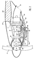
- FIG 2 we distinguish the elements principles of a turbomachine installed under wing 20 of an airplane.
- a turbomachine installed under wing 20 of an airplane.
- it is a turbine engine.
- the propeller 1 driven in rotation by the turbine 2, by through the speed reducer 3.
- the turbine 2 is supplied with air by internal air circulation 8, the entry of which is effected by an entry sleeve 7, placed just downstream of propeller 1, at the start of the hood 21 of the turbine engine.
- radiator cooling just downstream of this input sleeve 7.
- the latter is intended to supply the radiator 16 through which the lubricant passes and housed in a central part 12 of the cooling, i.e. downstream of the pipe of air supply there which widens in this part central unit 12.
- the air intake slot 10 therefore has a form of circular sector or in an arc, correspondence with the curvature of the inlet sleeve 7.
- the cooling device is completed by a discharge pipe 13, placed downstream of the central part 12 to extend the air circulation in the radiator 16 and evacuate this air to the nozzle 9 of the turbine engine 2.
- a temperature sensor (no shown), can ensure the maintenance of oil to the desired temperature and prevent its freezing.
- the circulation rate of the lubricant in the lubricant circuit 14 and in the radiator 16 is ensured by means of a pump driven by a support of equipment 23, or by means of a thermosyphon.
- Figure 3 is a view showing the part central 12 of the device inside which is installed the radiator 16. Downstream of these two parts is the ejector / lobe mixer 18 which is shown with a relatively large width. In done, the section of the central part 12, just like that of the air supply pipe 11 and the exhaust pipe 13 are relatively flat.
- FIG 4 distinguishes these elements by a view perpendicular to that of the Figure 3.
- this flat shape of the radiator 16 and the whole air circulation in the device cooling we understand that the size of the latter is not a disadvantage vis-à-vis the installation of the device on the turbomachine.
- this flat shape allows these pipes to be housed inside the cover of the turbine engine, around the elements main.
- only the radiator 16 has shown with the air supply line 11 and the discharge pipe 13 opening into the nozzle 9.
- Figure 4 also shows an implementation work of the valve 15 placed in the evacuation pipe 13. This valve can therefore more or less obstruct the exhaust pipe 13.
- the exhaust pipe 13 opens into the nozzle 9 and therefore does not increase the drag of the whole turbine engine.
- the air captured by the air intake slot 10 and passing through the device is enough to get the necessary cooling of the lubricant passed through the radiator 16.
- the regulating flap 15 can possibly be partially closed in the exhaust pipe 13. It is thus possible to maintain the lubricant at a desired temperature.
- the air flow passing through the radiator 16 is often insufficient.
- the increase in cooling air flow is therefore provided by the lobe ejector / mixer 18, controlled by the control valve 17.
- This regulation is done according to the regime or the power of the turbine engine, the temperature of the speed reducer 3 lubricant, or others parameters related to the gearbox, such as torque, regime, outside temperature.
- temperature of the lubricant then takeoff, that the ejector / lobe mixer 18 is closed by the valve 17.
- the air intake slot 10 in the shape of an arc circle or circumferential sector has a very cross section narrow in relation to the section of the entry sleeve 7, which solves the ingestion problem of large foreign bodies which could damage considerably the radiator.
- this small section of the slit air intake 10 greatly reduces the drag of the turbine engine nacelle by the absence of a scoop classic, such as that referenced 5 in the figure 1. It is also reported that the infrared signature front of the whole turbine engine is not increased by the use of such a grip slot air 10, which, in addition, can be located behind a particle trap.
- the radiator 16 of the cooling according to the invention is of size relatively small, because it is sized for the flight phases which are most representative of the mission of the aircraft (weight and oil gain).
- the possible inefficiency of the radiator is therefore offset by the supply of compressed air, via the ejector / lobe mixer 18 which causes the air flow to accelerate Venturi cooling.
- the lobe ejector-mixer 18 can be supplied by several supply lines taken from the level of the turbine engine compressor.
- Exhaust gas ejection speed in the nozzle 9 of the turbine 2 accelerates by suction the exhaust air circulating in the cooling device according to the invention and therefore increases the effectiveness thereof.
- Use compressed air, during the operating phases at idle or on the ground, allows effective cooling lubricant in the speed reducer.
- the freezing of the lubricant circulating in the radiator can easily be avoided and controlled, thanks to the modulation of the flow of air passing through the radiator, by means of the piloted flap 15.
Abstract
Description
L'invention se rapporte au domaine des turbomachines et, en particulier, aux turbopropulseurs, mais également aux turboréacteurs de grande puissance à double flux, tels que ceux utilisés en aéronautique civile et munis d'un réducteur de vitesse.The invention relates to the field of turbomachinery and, in particular, turboprop engines, but also to high power turbojet engines at double flow, such as those used in aeronautics civil and fitted with a speed reducer.
Pour accroítre leurs performances, tout en réduisant le bruit et la consommation de carburant, les turbomachines, telles que les turbopropulseurs, doivent posséder des hélices de type 〈〈 multipale 〉〉 de grand diamètre, à bas régime de rotation. Or, la puissance transmise à l'hélice tournant à faible vitesse, par le générateur de gaz tournant à grande vitesse, au moyen d'un réducteur mécanique de vitesse, engendre une grande quantité de chaleur due aux pertes mécaniques, c'est-à-dire aux frottements. On comprendra que cette chaleur doive être évacuée ou dissipée de manière efficace, pour éviter de dégrader rapidement les organes mécaniques du réducteur, tels que les engrenages et les paliers, ou de dégrader les qualités du lubrifiant du réducteur, sous peine de constater la chute du rendement de la turbomachine. Or, même avec un rendement proche ou dépassant légèrement les 99 %, le réducteur de vitesse d'une turbomachine d'une puissance mécanique de 10 000 kW dégage, malgré tout, une puissance thermique proche de 100 kw due aux pertes mécaniques.To increase their performance, while reducing noise and fuel consumption, turbomachinery, such as turboprop, must have large multi-blade propellers diameter, at low rotational speed. The power transmitted to the propeller rotating at low speed, by the gas generator rotating at high speed, using of a mechanical speed reducer, generates a large amount of heat due to mechanical losses, that is to say, friction. It will be understood that this heat must be removed or dissipated effective, to avoid rapidly degrading mechanical parts of the gear unit, such as gears and bearings, or degrade the qualities of the lubricant of the reducer, otherwise the drop in the efficiency of the turbomachine. Now even with a yield close to or slightly above 99%, the speed reducer of a turbomachine of a power mechanical power of 10,000 kW still gives off thermal power close to 100 kw due to losses mechanical.
Il est bien connu, dans le domaine de l'art antérieur, d'évacuer ce type de chaleur, c'est-à-dire de dissiper une telle puissance thermique, en faisant circuler le lubrifiant du réducteur de vitesse, en circuit fermé, au moyen d'une pompe ou d'un thermosiphon, dans un radiateur, tel qu'un radiateur à huile ou un échangeur air/huile.It is well known, in the field of art previous, to evacuate this type of heat, that is to say to dissipate such a thermal power, making circulate the lubricant of the speed reducer, closed circuit, by means of a pump or a thermosiphon, in a radiator, such as a radiator oil or an air / oil exchanger.
La figure 1 montre, en coupe, une réalisation
possible de ce refroidissement. Sur cette figure 1, on
distingue l'hélice 1 entraínée par le générateur de gaz
2, par l'intermédiaire du réducteur de vitesse 3.
Celui-ci est refroidi grâce à une circulation du
lubrifiant, par un circuit 4, dans un radiateur 6 placé
dans l'écope inférieure 5 du turbopropulseur. Le
radiateur 6 peut également être placé sous l'aile 20 de
l'avion, ou même latéralement.Figure 1 shows, in section, an embodiment
possible of this cooling. In this figure 1, we
distinguishes
Dans le cas de la figure 1, l'air en
mouvement traversant le radiateur 6 évacue la chaleur
vers l'extérieur de l'écope 5 et le lubrifiant refroidi
retourne dans le réducteur de vitesse 3 par le circuit
de refroidissement 4. Un volet peut éventuellement être
situé à l'entrée ou à la sortie de l'écope 5 pour
réguler le débit d'air traversant le radiateur 6, afin
de stabiliser la température du lubrifiant. En effet, à
grande vitesse, le radiateur 6 se trouve surdimensionné
par rapport aux basses vitesses. Or, il s'avère que ce
type de radiateur 6, en particulier les échangeurs
air/huile de réducteur, sont nécessairement de grande
taille, dans le but d'évacuer une importante puissance
thermique. C'est le cas notamment pendant les vols à
basses vitesses, ou même en position prolongée de
parking, la turbomachine fonctionnant au ralenti, et
enfin, lors des roulages sur les pistes. Un tel
matériel est donc lourd, encombrant, pénalise la
traínée de la turbomachine, nécessite une grande
quantité d'huile, et est très vulnérable aux ingestions
d'oiseaux.In the case of Figure 1, the air in
movement through the radiator 6 dissipates the heat
towards the outside of the
D'autre part, ce dernier inconvénient ne se pose pas avec un dispositif de refroidissement, tel que décrit par la demande de brevet français n° FR-A-2 742 479 du même déposant. En effet, dans ce système de refroidissement, on utilise le dispositif destiné au préalable à aspirer la couche limite de l'écoulement de l'air le long de la nacelle de la turbomachine, notamment dans la zone où cet écoulement devient turbulent, lorsque s'accroít la vitesse de l'avion. Ce système est composé de trous pratiqués sur le capot pour attirer l'air dans un collecteur où se trouve un échangeur de chaleur de grande longueur, faisant partie du dispositif de refroidissement.On the other hand, this last drawback is not do not install with a cooling device, such as described by the French patent application No. FR-A-2 742 479 from the same applicant. Indeed, in this cooling system, we use the device intended beforehand to vacuum the boundary layer of the air flow along the nacelle of the turbomachine, especially in the area where this flow becomes turbulent, when the speed of the plane. This system is composed of holes made on the hood to draw air into a manifold where finds a very long heat exchanger, forming part of the cooling device.
Or, compte tenu du très faible débit de ces trous d'aspiration, ce système nécessite la présence d'un échangeur de chaleur de très grande longueur, qui est donc très encombrant.However, given the very low flow rate of these suction holes, this system requires the presence a very long heat exchanger, which is therefore very bulky.
L'invention a donc pour but de remédier aux inconvénients ci-dessus mentionnés.The invention therefore aims to remedy the disadvantages mentioned above.
En considérant le fait qu'un avion passe plus de temps en vol à vitesse moyenne ou élevée qu'à basse vitesse ou au ralenti, il paraít astucieux de dimensionner le radiateur, air/huile, pour les phases de vol les plus longues et d'augmenter temporairement le débit d'air traversant ce radiateur 6 par un dispositif approprié pendant les phases les plus courtes, plutôt que de réduire le débit d'air traversant un radiateur surdimensionné à l'aide de volets.Considering the fact that an airplane passes more time in flight at medium or high speed than at low speed or idle, it seems clever to size the radiator, air / oil, for the phases longest flight times and temporarily increase the air flow through this radiator 6 by a suitable device during the most phases short, rather than reducing airflow going through an oversized radiator using shutters.
A cet effet, l'objet principal de l'invention est un dispositif de refroidissement d'un réducteur de vitesse de turbomachine, ledit réducteur étant lubrifié par un lubrifiant, la turbomachine possédant au moins une manche d'entrée de circuit de circulation interne de fluide et une tuyère, le dispositif de refroidissement comprenant :
- un radiateur destiné à refroidir le lubrifiant circulant à l'intérieur grâce à un circuit de lubrifiant ; et
- au moins une conduite d'amenée d'air aboutissant au radiateur.
- a radiator intended to cool the lubricant circulating inside thanks to a lubricant circuit; and
- at least one air supply line leading to the radiator.
Selon l'invention, le dispositif de refroidissement comprend au moins une fente de prise d'air, de section très réduite, placée dans la manche d'entrée du circuit de circulation interne de fluide de la turbomachine et prolongée par la conduite d'amenée d'air au radiateur.According to the invention, the device for cooling includes at least one plug slot air, of very small section, placed in the sleeve inlet of the internal circulation circuit of fluid the turbomachine and extended by the supply line air to the radiator.
Il est prévu que le dispositif de refroidissement soit équipé d'une conduite d'évacuation d'air à la sortie du radiateur, débouchant dans la tuyère de la turbomachine.It is expected that the cooling is equipped with a discharge pipe of air at the outlet of the radiator, opening into the turbomachine nozzle.
Afin de moduler le débit d'air dans le radiateur, il est également avantageux de prévoir la présence d'un volet monté pivotant dans la conduite d'évacuation d'air.In order to modulate the air flow in the radiator, it is also advantageous to provide the presence of a pivotally mounted flap in the pipe exhaust air.
Dans le but de permettre une circulation suffisante de l'air dans le radiateur, lorsque la circulation interne de fluide est insuffisante dans la turbomachine et de permettre d'utiliser un radiateur de taille réduite et dans le cas où la turbomachine possède au moins un compresseur, le dispositif de refroidissement selon l'invention comporte, en outre :
- au moins une conduite de prélèvement en air comprimé connectée sur le compresseur et débouchant dans la conduite d'évacuation avec un éjecteur/mélangeur ; et
- une vanne commandée par une unité de régulation de la turbomachine pour commander le débit d'air comprimé dans cette conduite d'alimentation en air comprimé.
- at least one compressed air sampling line connected to the compressor and opening into the evacuation line with an ejector / mixer; and
- a valve controlled by a turbomachine regulation unit for controlling the flow of compressed air in this compressed air supply pipe.
L'invention et ses différentes caractéristiques techniques seront mieux comprises à la lecture de la description détaillée suivante, illustrée de quelques figures représentant respectivement :
- figure 1, en coupe, une turbomachine équipée d'un dispositif de refroidissement de l'art antérieur ;
- figure 2, en coupe, une turbomachine équipée du dispositif de refroidissement selon l'invention ;
- figure 3, une vue partielle extérieure d'une partie du dispositif selon l'invention ;
- figure 4, une vue extérieure d'une grande partie du dispositif selon l'invention ; et
- figure 5, une vue cavalière extérieure de l'invention, installée sur une turbomachine.
- Figure 1, in section, a turbomachine equipped with a cooling device of the prior art;
- Figure 2, in section, a turbomachine equipped with the cooling device according to the invention;
- Figure 3, a partial exterior view of part of the device according to the invention;
- Figure 4, an external view of a large part of the device according to the invention; and
- FIG. 5, an external view of the invention, installed on a turbomachine.
Sur la figure 2, on distingue les éléments
principaux d'une turbomachine installée sous l'aile 20
d'un avion. Dans ce cas, il s'agit d'un turbomoteur.
Dans la partie amont de celui-ci se trouve l'hélice 1
entraínée en rotation par la turbine 2, par
l'intermédiaire du réducteur de vitesse 3. La turbine 2
est alimentée en air par une circulation interne d'air
8 dont l'entrée s'effectue par une manche d'entrée 7,
placée juste en aval de l'hélice 1, au début du capot
21 du turbomoteur.In Figure 2, we distinguish the elements
principles of a turbomachine installed under
Dans le but de ne pas handicaper le rendement
du turbomoteur, il a été choisi de prélever l'air de
refroidissement du radiateur juste en aval de cette
manche d'entrée 7. On utilise donc au moins une fente
de prise d'air 10, placée sur la circulation interne
d'air 8 de la turbomachine, en aval de la manche
d'entrée 7, pour alimenter une conduite d'amenée d'air
11. Cette dernière est destinée à alimenter le
radiateur 16 traversé par le lubrifiant et logé dans
une partie centrale 12 du dispositif de
refroidissement, c'est-à-dire en aval de la conduite
d'amenée d'air il qui s'élargit dans cette partie
centrale 12. La fente de prise d'air 10 a donc une
forme de secteur circulaire ou en arc de cercle, en
correspondance avec la courbure de la manche d'entrée
7.In order not to handicap performance
of the turbine engine, it was chosen to take air from
radiator cooling just downstream of this
input sleeve 7. We therefore use at least one
Le dispositif de refroidissement se complète
par une conduite d'évacuation 13, placée en aval de la
partie centrale 12 pour prolonger la circulation d'air
dans le radiateur 16 et évacuer cet air vers la tuyère
9 du turbomoteur 2. The cooling device is completed
by a
On comprend facilement que, à grande vitesse,
lors de vol de longue durée, ou par grand froid, l'air
pénétrant dans la fente de prise d'air 7, s'acheminant
par la conduite d'amenée il à travers le radiateur 16
et évacué vers la tuyère 9 par la conduite d'évacuation
13, puisse refroidir suffisamment le radiateur et le
lubrifiant, à savoir de l'huile, qui le traverse. Pour
moduler le débit d'air dans le dispositif de
refroidissement, on dispose un volet 15, en aval du
radiateur 16, dans la conduite d'évacuation 13. Ce
volet 15 est monté pivotant pour pouvoir constituer un
obstacle relatif à l'écoulement de l'air et diminuer
l'efficacité de la circulation de cet air dans le
dispositif de refroidissement. Un tel volet 15 peut
être avantageusement commandé par le dispositif de
régulation automatique du fonctionnement de la
turbomachine qui est de préférence du type : 〈〈 à pleine
autorité redondante 〉〉 c'est-à-dire du type 〈〈 FADEC 〉〉
(Full Authority Digital Engine Control) et actionné par
un moyen électrique, électromécanique, hydraulique ou
électrohydraulique connu tel qu'un vérin 24. Dans ce
type d'installation, une sonde de température (non
représentée), peut permettre d'assurer le maintien de
l'huile à la température souhaitée et d'empêcher son
figeage.We can easily understand that, at high speed,
during long flights, or in very cold weather, the air
penetrating into the air intake slot 7, traveling
by the supply line there through the
A faible vitesse, ou lors de phases plus
courtes, telles que les attentes en parking, les points
fixes, les ralentis au sol et les roulages par forte
chaleur, où la vitesse du vent relatif est faible ou
nulle, il s'avère utile d'accélérer le débit de
circulation d'air dans le dispositif de
refroidissement. A cet effet, on aménage en aval du
radiateur 16, dans la conduite d'évacuation 13, une
sortie d'air comprimé prélevé sur la turbomachine, de
préférence à la sortie du compresseur, au moyen d'une
conduite de prélèvement 19. Une vanne de régulation 17
est donc placée sur une telle conduite de prélèvement
19 et est pilotée également par le système central de
régulation du type 〈〈 FADEC 〉〉. La sortie de la conduite
de prélèvement 19 dans la conduite d'évacuation 13 est
un éjecteur/mélangeur à lobes 18.At low speed, or during longer phases
short, such as parking expectations, points
fixed, slowed down on the ground and taxiing by strong
heat, where the relative wind speed is low or
null, it is useful to accelerate the flow of
air circulation in the device
cooling. To this end, it is fitted downstream of the
L'éjection de l'air comprimé dans cet
éjecteur-mélangeur à lobes 18 accélère le flux d'air
provenant de la conduite d'amenée d'air 11 par un
phénomène d'aspiration (effet Venturi dû au
rétrécissement de section en aval de la partie centrale
12) et augmente le débit d'air de refroidissement
traversant le radiateur 16.The ejection of compressed air into this
lobe ejector-
Le débit de circulation du lubrifiant dans le
circuit de lubrifiant 14 et dans le radiateur 16 est
assuré au moyen d'une pompe entraínée par un support
d'équipements 23, ou au moyen d'un thermosiphon.The circulation rate of the lubricant in the
La figure 3 est une vue montrant la partie
centrale 12 du dispositif à l'intérieur de laquelle est
installé le radiateur 16. En aval de ces deux parties
se trouve l'éjecteur/mélangeur à lobes 18 qui est
représenté avec une largeur relativement importante. En
fait, la section de la partie centrale 12, tout comme
celle de la conduite d'amenée d'air 11 et de la
conduite d'évacuation 13 sont relativement plates.Figure 3 is a view showing the part
central 12 of the device inside which is
installed the
La figure 4 permet de distinguer ces éléments
par une vue perpendiculaire par rapport à celle de la
figure 3. Par cette forme plate du radiateur 16 et de
l'ensemble de la circulation d'air dans le dispositif
de refroidissement, on comprend que l'encombrement de
ce dernier ne soit pas un inconvénient vis-à-vis de
l'implantation du dispositif sur la turbomachine. Bien
au contraire, comme le montre bien la figure 5, cette
forme plate permet de loger ces conduites à l'intérieur
du capot du turbomoteur, autour des éléments
principaux. Sur cette figure 5, seul le radiateur 16 a
été représenté avec la conduite d'amenée d'air 11 et la
conduite d'évacuation 13 débouchant dans la tuyère 9.Figure 4 distinguishes these elements
by a view perpendicular to that of the
Figure 3. By this flat shape of the
La figure 4 montre également une mise en
oeuvre du clapet 15 placé dans la conduite d'évacuation
13. Ce clapet peut donc obstruer plus ou moins la
conduite d'évacuation 13. Sur cette figure 4, on
distingue également l'arrivée de la conduite d'air
comprimé 19, la vanne de régulation 17 et
l'éjecteur/mélangeur à lobes 18 placé en aval du
radiateur 16. La conduite d'évacuation 13 débouche dans
la tuyère 9 et n'augmente donc pas la traínée de
l'ensemble du turbomoteur.Figure 4 also shows an implementation
work of the
Le fait que les sections des différentes
conduites du dispositif selon l'invention soient
relativement plates est en accord avec la forme plate
de la fente de prise d'air 10 à l'entrée du dispositif,
dans la conduite 8 de la circulation interne d'air du
turbomoteur.The fact that the sections of the different
lines of the device according to the invention are
relatively flat is consistent with the flat shape
from the
Le fonctionnement du dispositif selon l'invention est le suivant.The operation of the device according to the invention is as follows.
A grande vitesse, ou par grand froid, l'air
capté par la fente de prise d'air 10 et traversant le
dispositif est suffisant pour obtenir le
refroidissement nécessaire du lubrifiant traversé dans
le radiateur 16. Le volet de régulation 15 peut
éventuellement être fermé partiellement dans la
conduite d'évacuation 13. Il est ainsi possible de
maintenir le lubrifiant à une température souhaitée.At high speed, or in very cold weather, the air
captured by the
Lors des phases d'attente, de vitesse
réduite, ou par forte chaleur, le débit d'air
traversant le radiateur 16 est souvent insuffisant.
L'augmentation de débit d'air de refroidissement est
donc apporté par l'éjecteur/mélangeur à lobes 18,
commandé par la vanne de régulation 17. Cette
régulation se fait en fonction du régime ou de la
puissance du turbomoteur, de la température du
lubrifiant du réducteur de vitesse 3, ou d'autres
paramètres liés au réducteur, tels que le couple, le
régime, la température extérieure. On note qu'il est
préférable, lors des phases de démarrage et de mise en
température du lubrifiant, puis le décollage, que
l'éjecteur/mélangeur à lobes 18 soit fermé par la vanne
de commande 17.During the waiting and speed phases
reduced, or in strong heat, the air flow
passing through the
La fente de prise d'air 10, en forme d'arc de
cercle ou de secteur circonférentiel a une section très
étroite par rapport à la section de la manche d'entrée
7, ce qui permet de résoudre le problème d'ingestion de
corps étrangers volumineux risquant d'endommager
considérablement le radiateur.The
De plus, cette faible section de la fente de
prise d'air 10 permet de diminuer fortement la traínée
de la nacelle du turbomoteur par l'absence d'une écope
classique, telle que celle référencée 5 sur la figure
1. On signale également que la signature infrarouge
frontale de l'ensemble du turbomoteur n'est pas
augmentée par l'utilisation d'une telle fente de prise
d'air 10, qui, de plus, peut être située derrière un
piège à particules.In addition, this small section of the
Le radiateur 16 du dispositif de
refroidissement selon l'invention est de taille
relativement réduite, car celui-ci est dimensionné pour
les phases de vol qui sont les plus représentatives de
la mission de l'avion (gain de masse et d'huile).The
Lors des autres phases d'utilisation du
turbomoteur, l'éventuel manque d'efficacité du
radiateur est donc pallié par l'apport d'air comprimé,
par l'intermédiaire de l'éjecteur/mélangeur à lobes 18
qui provoque l'accélération du débit d'air de
refroidissement par effet Venturi. On précise que
l'éjecteur-mélangeur à lobes 18 peut être alimenté par
plusieurs conduites d'alimentation prélevées au niveau
du compresseur du turbomoteur.During the other phases of use of the
turboshaft engine, the possible inefficiency of the
radiator is therefore offset by the supply of compressed air,
via the ejector /
La vitesse d'éjection des gaz d'échappement
dans la tuyère 9 de la turbine 2 accélère par
aspiration l'échappement de l'air circulant dans le
dispositif de refroidissement selon l'invention et
augmente donc l'efficacité de celui-ci. L'utilisation
de l'air comprimé, lors des phases de fonctionnement au
ralenti ou au sol, permet le refroidissement effectif
du lubrifiant dans le réducteur de vitesse.Exhaust gas ejection speed
in the
On réduit également la signature infra-rouge, à l'échappement, par l'injection d'air plus froid dans la tuyère et par l'absence de point chaud au niveau de la nacelle.We also reduce the infrared signature, at the exhaust, by injecting cooler air into the nozzle and by the absence of a hot spot at Platform.
Le figeage du lubrifiant circulant dans le
radiateur peut facilement être évité et contrôlé, grâce
à la modulation de la circulation de l'air traversant
le radiateur, au moyen du volet piloté 15.The freezing of the lubricant circulating in the
radiator can easily be avoided and controlled, thanks
to the modulation of the flow of air passing through
the radiator, by means of the piloted
Claims (4)
Applications Claiming Priority (2)
| Application Number | Priority Date | Filing Date | Title |
|---|---|---|---|
| FR9900082A FR2788308A1 (en) | 1999-01-07 | 1999-01-07 | COOLING DEVICE FOR A TURBOMACHINE SPEED REDUCER |
| FR9900082 | 1999-01-07 |
Publications (2)
| Publication Number | Publication Date |
|---|---|
| EP1018468A1 true EP1018468A1 (en) | 2000-07-12 |
| EP1018468B1 EP1018468B1 (en) | 2004-12-08 |
Family
ID=9540666
Family Applications (1)
| Application Number | Title | Priority Date | Filing Date |
|---|---|---|---|
| EP00400017A Expired - Lifetime EP1018468B1 (en) | 1999-01-07 | 2000-01-06 | Turbomachine with a reduction gear equipped with a cooling device |
Country Status (5)
| Country | Link |
|---|---|
| US (1) | US6282881B1 (en) |
| EP (1) | EP1018468B1 (en) |
| CA (1) | CA2294620C (en) |
| DE (1) | DE60016474T2 (en) |
| FR (1) | FR2788308A1 (en) |
Cited By (9)
| Publication number | Priority date | Publication date | Assignee | Title |
|---|---|---|---|---|
| FR2891248A1 (en) * | 2005-09-28 | 2007-03-30 | Airbus France Sas | Engine e.g. jet engine, assembly for aircraft, has heat exchange system with outlet situated between shell and engine and rearwards with respect to rear engine attachment interposed between engine and engine mounting structure |
| EP1944475A3 (en) * | 2007-01-08 | 2010-11-03 | United Technologies Corporation | Heat exchange system |
| EP1876328A3 (en) * | 2006-07-06 | 2010-11-03 | United Technologies Corporation | Heat exchange system in a turbofan engine |
| FR2946089A1 (en) * | 2009-05-27 | 2010-12-03 | Airbus France | FLUID COOLING DEVICE FOR TURBOMACHINE PROPELLER |
| EP2337940A1 (en) * | 2008-09-22 | 2011-06-29 | Rolls-Royce Corporation | Thermal management system |
| EP2366625A3 (en) * | 2010-03-04 | 2013-12-25 | Rolls-Royce Deutschland Ltd & Co KG | Aircraft engine with optimised oil heat exchanger |
| FR3023587A1 (en) * | 2014-07-10 | 2016-01-15 | Turbomeca | TURBOMACHINE WITH AUTONOMOUS COOLING SYSTEM OF EQUIPMENT. |
| FR3028888A1 (en) * | 2014-11-25 | 2016-05-27 | Snecma | COOLING DEVICE FOR A TURBOMACHINE SUPPLIED BY A DISCHARGE CIRCUIT |
| WO2016083743A1 (en) | 2014-11-27 | 2016-06-02 | Snecma | Arrangements for drawing in air and trapping foreign bodies in an aircraft propulsion assembly |
Families Citing this family (63)
| Publication number | Priority date | Publication date | Assignee | Title |
|---|---|---|---|---|
| US6415595B1 (en) * | 2000-08-22 | 2002-07-09 | Hamilton Sundstrand Corporation | Integrated thermal management and coolant system for an aircraft |
| US6651929B2 (en) | 2001-10-29 | 2003-11-25 | Pratt & Whitney Canada Corp. | Passive cooling system for auxiliary power unit installation |
| GB2389174B (en) * | 2002-05-01 | 2005-10-26 | Rolls Royce Plc | Cooling systems |
| DE10233947A1 (en) * | 2002-07-25 | 2004-02-12 | Siemens Ag | Wind power system has generator in gondola, turbine with rotor blade(s); generator has a closed primary cooling circuit; the gondola has an arrangement enabling cooling of primary cooling circuit |
| US20040107077A1 (en) * | 2002-11-30 | 2004-06-03 | Moitreyee Sinha | Models for predicting perception of an item of interest |
| US7260926B2 (en) * | 2004-01-20 | 2007-08-28 | United Technologies Corporation | Thermal management system for an aircraft |
| US7231767B2 (en) * | 2004-04-16 | 2007-06-19 | Pratt & Whitney Canada Corp. | Forced air cooling system |
| US7454894B2 (en) * | 2004-12-07 | 2008-11-25 | United Technologies Corporation | Supplemental oil cooler airflow for gas turbine engine |
| US7434765B2 (en) * | 2005-02-16 | 2008-10-14 | The Boeing Company | Heat exchanger systems and associated systems and methods for cooling aircraft starter/generators |
| US7720368B2 (en) * | 2005-07-15 | 2010-05-18 | Redrock Microsystems, Llc | System, method and apparatus for enhancing a projected image |
| EP1928734A4 (en) * | 2005-09-20 | 2012-03-28 | Volvo Aero Corp | Cooling system for an aircraft, aircrft comprising the cooling system and cooling method |
| FR2902830B1 (en) * | 2006-06-27 | 2008-08-08 | Airbus France Sas | TURBOREACTOR FOR AIRCRAFT |
| US7658060B2 (en) * | 2006-07-19 | 2010-02-09 | United Technologies Corporation | Lubricant cooling exchanger dual intake duct |
| EP2074317B1 (en) * | 2006-10-12 | 2012-03-07 | United Technologies Corporation | Nacelle assembly for a gas turbine engine comprising a pylon located in the fan bypass flow path with a variable area flow system |
| US7665310B2 (en) * | 2006-12-27 | 2010-02-23 | General Electric Company | Gas turbine engine having a cooling-air nacelle-cowl duct integral with a nacelle cowl |
| US8516791B2 (en) * | 2007-07-30 | 2013-08-27 | General Electric Company | Methods and apparatus for mixing fluid in turbine engines |
| US7578369B2 (en) * | 2007-09-25 | 2009-08-25 | Hamilton Sundstrand Corporation | Mixed-flow exhaust silencer assembly |
| DE102008028987A1 (en) | 2008-06-20 | 2009-12-24 | Rolls-Royce Deutschland Ltd & Co Kg | Turboprop engine with a device for generating a cooling air flow |
| US9885313B2 (en) | 2009-03-17 | 2018-02-06 | United Technologes Corporation | Gas turbine engine bifurcation located fan variable area nozzle |
| US20100326049A1 (en) * | 2009-06-25 | 2010-12-30 | Honeywell International Inc. | Cooling systems for rotorcraft engines |
| US8991191B2 (en) * | 2009-11-24 | 2015-03-31 | General Electric Company | Thermally actuated passive gas turbine engine compartment venting |
| US20110182723A1 (en) * | 2010-01-26 | 2011-07-28 | Airbus Operations (S.A.S) | Turbomachine aircraft propeller |
| US8973552B2 (en) | 2011-06-27 | 2015-03-10 | United Technologies Corporation | Integral oil system |
| FR2979136B1 (en) * | 2011-08-16 | 2014-11-14 | Snecma | DEVICE FOR ACTIVATING A PASSIVE EJECTOR VALVE FOR PRESSURIZING AN AIRCRAFT TURBOEER SPEAKER |
| US8756911B1 (en) * | 2011-11-16 | 2014-06-24 | Florida Turbine Technologies, Inc. | Turbine exhaust cylinder and strut cooling |
| US8261527B1 (en) * | 2012-01-31 | 2012-09-11 | United Technologies Corporation | Gas turbine engine with geared turbofan and oil thermal management system with unique heat exchanger structure |
| US9194294B2 (en) * | 2012-05-07 | 2015-11-24 | United Technologies Corporation | Gas turbine engine oil tank |
| US20140140824A1 (en) * | 2012-10-26 | 2014-05-22 | United Technologies Corporation | Oil system bearing compartment architecture for gas turbine engine |
| US20140119903A1 (en) * | 2012-10-29 | 2014-05-01 | United Technologies Corporation | Gas Turbine Engine With Inlet Particle Separator and Thermal Management |
| US9739171B2 (en) | 2012-11-16 | 2017-08-22 | United Technologies Corporation | Turbine engine cooling system with an open loop circuit |
| US9458764B2 (en) | 2012-11-26 | 2016-10-04 | Pratt & Whitney Canada Corp. | Air cooled air cooler for gas turbine engine air system |
| EP2932068B1 (en) * | 2012-12-13 | 2017-11-15 | United Technologies Corporation | Gas turbine engine with cooling scheme for drive gear system and pitch control |
| EP2981697B1 (en) * | 2013-01-21 | 2019-10-02 | United Technologies Corporation | Air oil cooler airflow augmentation system and corresponding method |
| WO2015050579A2 (en) | 2013-01-21 | 2015-04-09 | United Technologies Corporation | Gas turbine engine with geared turbofan and oil thermal management system with unique heat exchanger structure |
| WO2014120125A1 (en) | 2013-01-29 | 2014-08-07 | United Technologies Corporation | Gas turbine engine with lower bifurcation heat exchanger |
| US9840967B2 (en) * | 2013-03-04 | 2017-12-12 | Rolls-Royce North American Technologies, Inc. | Ram air thermal management system |
| EP3428427B1 (en) | 2013-03-15 | 2020-09-02 | United Technologies Corporation | Gas turbine engine with air-oil cooler oil tank |
| FR3003902A1 (en) | 2013-03-26 | 2014-10-03 | Aircelle Sa | COOLING DEVICE FOR A TURBOMOTOR OF AN AIRCRAFT NACELLE |
| FR3008449B1 (en) * | 2013-07-12 | 2015-07-24 | Snecma | OIL COOLING DEVICE FOR A TURBOMACHINE |
| FR3010699A1 (en) * | 2013-09-19 | 2015-03-20 | Airbus Operations Sas | FITTING DEVICE FOR A PROPELLANT AIRCRAFT ASSEMBLY COMPRISING AN INTERIOR COMPARTMENT EQUIPPED WITH A FAN |
| US9938855B2 (en) | 2014-01-31 | 2018-04-10 | Pratt & Whitney Canada Corp. | Cooling system and method for supplying a cooling gas flow |
| US9745962B2 (en) | 2014-03-10 | 2017-08-29 | X Development Llc | Radiator configuration for a flying wind turbine that passively controls airflow |
| FR3019855B1 (en) * | 2014-04-14 | 2016-04-01 | Airbus Operations Sas | AIRCRAFT PROPULSIVE ASSEMBLY COMPRISING A VARIABLE FLOW AIR VALVE |
| FR3022588B1 (en) * | 2014-06-24 | 2016-06-24 | Snecma | COOLING DEVICE FOR A TURBOMACHINE |
| US10415475B2 (en) | 2014-07-31 | 2019-09-17 | Sikorsky Aircraft Corporation | Gearbox oil cooling assembly |
| US9896998B2 (en) | 2015-02-20 | 2018-02-20 | Pratt & Whitney Canada Corp. | Compound engine assembly with modulated flow |
| US9932892B2 (en) | 2015-02-20 | 2018-04-03 | Pratt & Whitney Canada Corp. | Compound engine assembly with coaxial compressor and offset turbine section |
| US9879591B2 (en) | 2015-02-20 | 2018-01-30 | Pratt & Whitney Canada Corp. | Engine intake assembly with selector valve |
| US9797297B2 (en) | 2015-02-20 | 2017-10-24 | Pratt & Whitney Canada Corp. | Compound engine assembly with common inlet |
| US10253726B2 (en) | 2015-08-07 | 2019-04-09 | Pratt & Whitney Canada Corp. | Engine assembly with combined engine and cooling exhaust |
| US10267191B2 (en) * | 2015-08-07 | 2019-04-23 | Pratt & Whitney Canada Corp. | Turboprop engine assembly with combined engine and cooling exhaust |
| US10240522B2 (en) | 2015-08-07 | 2019-03-26 | Pratt & Whitney Canada Corp. | Auxiliary power unit with combined cooling of generator |
| FR3044636B1 (en) * | 2015-12-08 | 2019-08-30 | Safran Aircraft Engines | AIRCRAFT TURBOMACHINE EQUIPPED WITH AIR-OIL SURFACE HEAT EXCHANGER |
| CN206942877U (en) * | 2017-05-03 | 2018-01-30 | 深圳光启合众科技有限公司 | Ducted fan |
| US10527012B2 (en) * | 2017-06-29 | 2020-01-07 | Pratt & Whitney Canada Corp. | Engine assembly with engine and cooler compartments |
| GB201720727D0 (en) | 2017-12-13 | 2018-01-24 | Rolls Royce Plc | Bleed Ejector |
| JP2020200940A (en) * | 2019-06-10 | 2020-12-17 | 宮内 直 | Outer cylinder of propulsion machine such as flying car |
| US11635024B2 (en) | 2019-08-16 | 2023-04-25 | Pratt & Whitney Canada Corp. | Pusher turboprop powerplant installation |
| CN112158326B (en) * | 2020-09-11 | 2023-03-14 | 中国航空工业集团公司成都飞机设计研究所 | Ventral fin type radiator suitable for aircraft |
| US11512639B2 (en) * | 2021-01-26 | 2022-11-29 | General Electric Company | Heat transfer system |
| CN113022858A (en) * | 2021-03-04 | 2021-06-25 | 中国电子科技集团公司第二十九研究所 | Nacelle air inlet and exhaust device |
| WO2023194665A1 (en) * | 2022-04-04 | 2023-10-12 | Safran Aircraft Engines | Gas turbine provided with an unducted propeller comprising a cooling air duct and a variable bleed valve exhaust duct |
| US20240092496A1 (en) * | 2022-09-20 | 2024-03-21 | Pratt & Whitney Canada Corp. | Exhaust nozzle assembly for an aircraft propulsion system |
Citations (6)
| Publication number | Priority date | Publication date | Assignee | Title |
|---|---|---|---|---|
| US4351150A (en) * | 1980-02-25 | 1982-09-28 | General Electric Company | Auxiliary air system for gas turbine engine |
| WO1992011451A1 (en) * | 1990-12-21 | 1992-07-09 | Rolls-Royce Plc | Heat exchange apparatus for gas turbine fluids |
| EP0514119A1 (en) * | 1991-05-16 | 1992-11-19 | General Electric Company | Nacelle cooling and ventilation system |
| US5265408A (en) * | 1992-02-13 | 1993-11-30 | Allied-Signal Inc. | Exhaust eductor cooling system |
| EP0743247A2 (en) * | 1995-05-15 | 1996-11-20 | The Boeing Company | Passive cooling device and method for cooling an auxiliary power unit on an airoplane |
| DE19524731A1 (en) * | 1995-07-07 | 1997-01-09 | Bmw Rolls Royce Gmbh | Turboprop engine with an air-oil cooler |
Family Cites Families (8)
| Publication number | Priority date | Publication date | Assignee | Title |
|---|---|---|---|---|
| US4409788A (en) * | 1979-04-23 | 1983-10-18 | General Electric Company | Actuation system for use on a gas turbine engine |
| US4765131A (en) * | 1985-02-08 | 1988-08-23 | Allied Signal Inc. | Aircraft engine bleed air flow balancing technique |
| DE3828834C1 (en) * | 1988-08-25 | 1989-11-02 | Mtu Muenchen Gmbh | |
| US5553449A (en) * | 1993-12-21 | 1996-09-10 | United Technologies Corporation | Method of operating a gas turbine engine powerplant for an aircraft |
| DE19524733A1 (en) * | 1995-07-07 | 1997-01-09 | Bmw Rolls Royce Gmbh | Aircraft gas turbine engine with a liquid-air heat exchanger |
| FR2742479B1 (en) | 1995-12-13 | 1998-01-16 | Snecma | DEVICE FOR COOLING A TURBOMOTOR ON AN AIRCRAFT |
| US6058696A (en) * | 1997-12-22 | 2000-05-09 | United Technologies Corporation | Inlet and outlet module for a heat exchanger for a flowpath for working medium gases |
| US6092360A (en) * | 1998-07-01 | 2000-07-25 | The Boeing Company | Auxiliary power unit passive cooling system |
-
1999
- 1999-01-07 FR FR9900082A patent/FR2788308A1/en active Pending
-
2000
- 2000-01-03 US US09/476,083 patent/US6282881B1/en not_active Expired - Lifetime
- 2000-01-05 CA CA002294620A patent/CA2294620C/en not_active Expired - Lifetime
- 2000-01-06 DE DE60016474T patent/DE60016474T2/en not_active Expired - Lifetime
- 2000-01-06 EP EP00400017A patent/EP1018468B1/en not_active Expired - Lifetime
Patent Citations (6)
| Publication number | Priority date | Publication date | Assignee | Title |
|---|---|---|---|---|
| US4351150A (en) * | 1980-02-25 | 1982-09-28 | General Electric Company | Auxiliary air system for gas turbine engine |
| WO1992011451A1 (en) * | 1990-12-21 | 1992-07-09 | Rolls-Royce Plc | Heat exchange apparatus for gas turbine fluids |
| EP0514119A1 (en) * | 1991-05-16 | 1992-11-19 | General Electric Company | Nacelle cooling and ventilation system |
| US5265408A (en) * | 1992-02-13 | 1993-11-30 | Allied-Signal Inc. | Exhaust eductor cooling system |
| EP0743247A2 (en) * | 1995-05-15 | 1996-11-20 | The Boeing Company | Passive cooling device and method for cooling an auxiliary power unit on an airoplane |
| DE19524731A1 (en) * | 1995-07-07 | 1997-01-09 | Bmw Rolls Royce Gmbh | Turboprop engine with an air-oil cooler |
Cited By (21)
| Publication number | Priority date | Publication date | Assignee | Title |
|---|---|---|---|---|
| WO2007036523A1 (en) * | 2005-09-28 | 2007-04-05 | Airbus France | Engine assembly for an aircraft comprising an engine as well as an engine mounting structure for such an engine |
| WO2007036522A1 (en) * | 2005-09-28 | 2007-04-05 | Airbus France | Engine assembly for an aircraft comprising an engine as well as an engine mounting structure for such an engine |
| FR2891248A1 (en) * | 2005-09-28 | 2007-03-30 | Airbus France Sas | Engine e.g. jet engine, assembly for aircraft, has heat exchange system with outlet situated between shell and engine and rearwards with respect to rear engine attachment interposed between engine and engine mounting structure |
| US7971826B2 (en) | 2005-09-28 | 2011-07-05 | Airbus Operations Sas | Engine assembly for an aircraft comprising an engine as well as an engine mounting structure for such an engine |
| US8061649B2 (en) | 2005-09-28 | 2011-11-22 | Airbus Operations Sas | Engine assembly for an aircraft comprising an engine as well as an engine mounting structure for such an engine |
| EP1876328A3 (en) * | 2006-07-06 | 2010-11-03 | United Technologies Corporation | Heat exchange system in a turbofan engine |
| US8161726B2 (en) | 2006-07-06 | 2012-04-24 | United Technologies Corporation | Cooling exchanger duct |
| EP1944475A3 (en) * | 2007-01-08 | 2010-11-03 | United Technologies Corporation | Heat exchange system |
| US8157503B2 (en) | 2008-09-22 | 2012-04-17 | Rolls Royce Corporation | Thermal management system |
| EP2337940A1 (en) * | 2008-09-22 | 2011-06-29 | Rolls-Royce Corporation | Thermal management system |
| EP2337940A4 (en) * | 2008-09-22 | 2012-02-29 | Rolls Royce Corp | Thermal management system |
| FR2946089A1 (en) * | 2009-05-27 | 2010-12-03 | Airbus France | FLUID COOLING DEVICE FOR TURBOMACHINE PROPELLER |
| WO2010136710A3 (en) * | 2009-05-27 | 2011-04-14 | Airbus Operations (S.A.S) | Fluid-cooling device for a turbine engine propulsive unit |
| US9175695B2 (en) | 2009-05-27 | 2015-11-03 | Airbus Operations S.A.S. | Fluid-cooling device for a turbine engine propulsive unit |
| EP2366625A3 (en) * | 2010-03-04 | 2013-12-25 | Rolls-Royce Deutschland Ltd & Co KG | Aircraft engine with optimised oil heat exchanger |
| US8690098B2 (en) | 2010-03-04 | 2014-04-08 | Rolls-Royce Deutschland Ltd & Co Kg | Air ejector nozzle tube for an oil heat exchanger of an aircraft engine |
| FR3023587A1 (en) * | 2014-07-10 | 2016-01-15 | Turbomeca | TURBOMACHINE WITH AUTONOMOUS COOLING SYSTEM OF EQUIPMENT. |
| FR3028888A1 (en) * | 2014-11-25 | 2016-05-27 | Snecma | COOLING DEVICE FOR A TURBOMACHINE SUPPLIED BY A DISCHARGE CIRCUIT |
| WO2016083732A1 (en) | 2014-11-25 | 2016-06-02 | Snecma | Cooling device for a turbomachine supplied by a discharge circuit |
| US10883422B2 (en) | 2014-11-25 | 2021-01-05 | Snecma | Cooling device for a turbomachine supplied by a discharge circuit |
| WO2016083743A1 (en) | 2014-11-27 | 2016-06-02 | Snecma | Arrangements for drawing in air and trapping foreign bodies in an aircraft propulsion assembly |
Also Published As
| Publication number | Publication date |
|---|---|
| CA2294620A1 (en) | 2000-07-07 |
| US6282881B1 (en) | 2001-09-04 |
| EP1018468B1 (en) | 2004-12-08 |
| DE60016474T2 (en) | 2005-12-15 |
| DE60016474D1 (en) | 2005-01-13 |
| CA2294620C (en) | 2006-05-23 |
| FR2788308A1 (en) | 2000-07-13 |
Similar Documents
| Publication | Publication Date | Title |
|---|---|---|
| EP1018468B1 (en) | Turbomachine with a reduction gear equipped with a cooling device | |
| EP2819921B1 (en) | Engine nacelle comprising a heat exchanger | |
| EP2472067B1 (en) | Integration of a surface heat exchanger with controlled air flow in an airplane engine | |
| EP3224462B1 (en) | Cooling device for a turbomachine supplied by a discharge circuit | |
| CA2904311C (en) | Cooling device for a turbo engine of an aircraft nacelle | |
| EP3013689B1 (en) | De-icing and conditioning device for an aircraft | |
| EP1881181B1 (en) | Turbomachine | |
| FR2659389A1 (en) | LIMIT LAYER DISCHARGE SYSTEM INTEGRATED INTO THE STARTER OF AN AIRCRAFT ENGINE. | |
| FR2635824A1 (en) | GAS TURBOMOTEUR TURBOMOTOR DRIVEN BY A ROTORS REDUCER WITH PROPELLERS OR BLOWER ROTORS | |
| EP3070317B1 (en) | Evaporative cooling of a turbine engine | |
| EP2964906B1 (en) | Nacelle equipped with an oil-cooling circuit comprising an intermediate heat exchanger | |
| FR3027624A1 (en) | CIRCUIT FOR DEFROSTING AN AIR INLET LIP FROM A PROPELLANT AIRCRAFT ASSEMBLY | |
| FR3039133A1 (en) | AIRCRAFT WITH A PROPULSIVE ASSEMBLY COMPRISING A BLOWER AT THE REAR OF THE FUSELAGE | |
| EP2576994A1 (en) | Method and system for controlling the clearance at the blade tips of a turbine rotor | |
| WO2015128563A1 (en) | Fan rotor for a turbo machine such as a multiple flow turbojet engine driven by a reduction gear | |
| FR2976018A1 (en) | VARIABLE TIMING RADIAL TURBINE DISPENSER, ESPECIALLY AUXILIARY POWER SOURCE TURBINE | |
| FR2742479A1 (en) | DEVICE FOR COOLING A TURBOMOTOR ON AN AIRCRAFT | |
| FR3088955A1 (en) | Double-flow turbojet engine comprising an outlet cone cooled by its secondary flow | |
| WO2015197974A1 (en) | Cooling device for a turbomachine | |
| FR3054858A1 (en) | TURBOMACHINE COMPRISING A DEVICE FOR DRIVING EQUIPMENT ARRANGED IN THE EXHAUST CONE | |
| FR3039208A1 (en) | DEFROSTING AN AIR INLET LIP AND COOLING A TURBINE HOUSING OF A PROPELLANT AIRCRAFT ASSEMBLY | |
| FR3107307A1 (en) | Heat recovery system for propulsion system | |
| FR3042820A1 (en) | DEVICE FOR VENTILATION OF A TURBOMACHINE COMPARTMENT | |
| FR3108657A1 (en) | Turbine rotor comprising a device for regulating the flow of cooling fluid and turbomachine comprising such a rotor |
Legal Events
| Date | Code | Title | Description |
|---|---|---|---|
| PUAI | Public reference made under article 153(3) epc to a published international application that has entered the european phase |
Free format text: ORIGINAL CODE: 0009012 |
|
| 17P | Request for examination filed |
Effective date: 20000114 |
|
| AK | Designated contracting states |
Kind code of ref document: A1 Designated state(s): DE FR GB IT |
|
| AX | Request for extension of the european patent |
Free format text: AL;LT;LV;MK;RO;SI |
|
| AKX | Designation fees paid |
Free format text: DE FR GB IT |
|
| 17Q | First examination report despatched |
Effective date: 20031219 |
|
| GRAP | Despatch of communication of intention to grant a patent |
Free format text: ORIGINAL CODE: EPIDOSNIGR1 |
|
| RTI1 | Title (correction) |
Free format text: TURBOMACHINE WITH A REDUCTION GEAR EQUIPPED WITH A COOLING DEVICE |
|
| GRAP | Despatch of communication of intention to grant a patent |
Free format text: ORIGINAL CODE: EPIDOSNIGR1 |
|
| GRAS | Grant fee paid |
Free format text: ORIGINAL CODE: EPIDOSNIGR3 |
|
| GRAA | (expected) grant |
Free format text: ORIGINAL CODE: 0009210 |
|
| AK | Designated contracting states |
Kind code of ref document: B1 Designated state(s): DE FR GB IT |
|
| REG | Reference to a national code |
Ref country code: GB Ref legal event code: FG4D Free format text: NOT ENGLISH |
|
| REF | Corresponds to: |
Ref document number: 60016474 Country of ref document: DE Date of ref document: 20050113 Kind code of ref document: P |
|
| GBT | Gb: translation of ep patent filed (gb section 77(6)(a)/1977) |
Effective date: 20050113 |
|
| RAP2 | Party data changed (patent owner data changed or rights of a patent transferred) |
Owner name: SNECMA |
|
| PLBE | No opposition filed within time limit |
Free format text: ORIGINAL CODE: 0009261 |
|
| STAA | Information on the status of an ep patent application or granted ep patent |
Free format text: STATUS: NO OPPOSITION FILED WITHIN TIME LIMIT |
|
| 26N | No opposition filed |
Effective date: 20050909 |
|
| REG | Reference to a national code |
Ref country code: FR Ref legal event code: PLFP Year of fee payment: 17 |
|
| REG | Reference to a national code |
Ref country code: FR Ref legal event code: PLFP Year of fee payment: 18 |
|
| REG | Reference to a national code |
Ref country code: FR Ref legal event code: PLFP Year of fee payment: 19 |
|
| REG | Reference to a national code |
Ref country code: FR Ref legal event code: CD Owner name: SAFRAN AIRCRAFT ENGINES Effective date: 20170719 |
|
| PGFP | Annual fee paid to national office [announced via postgrant information from national office to epo] |
Ref country code: FR Payment date: 20181220 Year of fee payment: 20 Ref country code: GB Payment date: 20181219 Year of fee payment: 20 |
|
| PGFP | Annual fee paid to national office [announced via postgrant information from national office to epo] |
Ref country code: IT Payment date: 20190102 Year of fee payment: 20 Ref country code: DE Payment date: 20181218 Year of fee payment: 20 |
|
| REG | Reference to a national code |
Ref country code: DE Ref legal event code: R071 Ref document number: 60016474 Country of ref document: DE |
|
| REG | Reference to a national code |
Ref country code: GB Ref legal event code: PE20 Expiry date: 20200105 |
|
| PG25 | Lapsed in a contracting state [announced via postgrant information from national office to epo] |
Ref country code: GB Free format text: LAPSE BECAUSE OF EXPIRATION OF PROTECTION Effective date: 20200105 |