EP1018435A2 - Printer with floating print head - Google Patents
Printer with floating print head Download PDFInfo
- Publication number
- EP1018435A2 EP1018435A2 EP99203604A EP99203604A EP1018435A2 EP 1018435 A2 EP1018435 A2 EP 1018435A2 EP 99203604 A EP99203604 A EP 99203604A EP 99203604 A EP99203604 A EP 99203604A EP 1018435 A2 EP1018435 A2 EP 1018435A2
- Authority
- EP
- European Patent Office
- Prior art keywords
- printer
- lid
- printhead
- platen
- paper
- Prior art date
- Legal status (The legal status is an assumption and is not a legal conclusion. Google has not performed a legal analysis and makes no representation as to the accuracy of the status listed.)
- Withdrawn
Links
Images


Classifications
-
- B—PERFORMING OPERATIONS; TRANSPORTING
- B41—PRINTING; LINING MACHINES; TYPEWRITERS; STAMPS
- B41J—TYPEWRITERS; SELECTIVE PRINTING MECHANISMS, i.e. MECHANISMS PRINTING OTHERWISE THAN FROM A FORME; CORRECTION OF TYPOGRAPHICAL ERRORS
- B41J15/00—Devices or arrangements of selective printing mechanisms, e.g. ink-jet printers or thermal printers, specially adapted for supporting or handling copy material in continuous form, e.g. webs
- B41J15/04—Supporting, feeding, or guiding devices; Mountings for web rolls or spindles
- B41J15/042—Supporting, feeding, or guiding devices; Mountings for web rolls or spindles for loading rolled-up continuous copy material into printers, e.g. for replacing a used-up paper roll; Point-of-sale printers with openable casings allowing access to the rolled-up continuous copy material
-
- B—PERFORMING OPERATIONS; TRANSPORTING
- B41—PRINTING; LINING MACHINES; TYPEWRITERS; STAMPS
- B41J—TYPEWRITERS; SELECTIVE PRINTING MECHANISMS, i.e. MECHANISMS PRINTING OTHERWISE THAN FROM A FORME; CORRECTION OF TYPOGRAPHICAL ERRORS
- B41J2/00—Typewriters or selective printing mechanisms characterised by the printing or marking process for which they are designed
- B41J2/315—Typewriters or selective printing mechanisms characterised by the printing or marking process for which they are designed characterised by selective application of heat to a heat sensitive printing or impression-transfer material
- B41J2/32—Typewriters or selective printing mechanisms characterised by the printing or marking process for which they are designed characterised by selective application of heat to a heat sensitive printing or impression-transfer material using thermal heads
-
- B—PERFORMING OPERATIONS; TRANSPORTING
- B41—PRINTING; LINING MACHINES; TYPEWRITERS; STAMPS
- B41J—TYPEWRITERS; SELECTIVE PRINTING MECHANISMS, i.e. MECHANISMS PRINTING OTHERWISE THAN FROM A FORME; CORRECTION OF TYPOGRAPHICAL ERRORS
- B41J25/00—Actions or mechanisms not otherwise provided for
- B41J25/304—Bodily-movable mechanisms for print heads or carriages movable towards or from paper surface
- B41J25/312—Bodily-movable mechanisms for print heads or carriages movable towards or from paper surface with print pressure adjustment mechanisms, e.g. pressure-on-the paper mechanisms
-
- B—PERFORMING OPERATIONS; TRANSPORTING
- B41—PRINTING; LINING MACHINES; TYPEWRITERS; STAMPS
- B41J—TYPEWRITERS; SELECTIVE PRINTING MECHANISMS, i.e. MECHANISMS PRINTING OTHERWISE THAN FROM A FORME; CORRECTION OF TYPOGRAPHICAL ERRORS
- B41J25/00—Actions or mechanisms not otherwise provided for
- B41J25/304—Bodily-movable mechanisms for print heads or carriages movable towards or from paper surface
- B41J25/316—Bodily-movable mechanisms for print heads or carriages movable towards or from paper surface with tilting motion mechanisms relative to paper surface
Definitions
- the invention relates to a print head mechanism in a printer. More particularly, it relates to a floating print head mechanism attached to the printer lid so that new paper can be loaded into the printer without the cumbersome procedure of threading the paper through the print mechanism.
- Printers are available in many different configurations utilizing a variety of technologies. The choice of the best features and technologies for a particular application depends on a number of factors including cost, print speed, print quality, durability and operating expenses. Regardless of the type of technology used, however, most printers have three elements in common: 1) a print head located on the side of the paper to be printed; 2) a platen located on the opposite side of the paper and providing physical support for the paper; and 3) a paper handling mechanism which moves the paper past the print head. In some cases the platen and the paper handling mechanism can be combined into a single roller which presses the paper against the print head and turns to advance the paper forward.
- This configuration is especially advantageous as it combines into a single item the functions of advancing the paper, providing a relatively hard surface against which the paper may he held, and maintaining the paper against the print head for a precision printing operation.
- Such rollers typically have a roller surface which is slightly compressible and which exhibits sufficient friction against the paper to move the paper with the required precision.
- Such rollers are well known in the printer industry and are not further described here.
- Some printers will print on cut-sheet paper, which requires a complicated and expensive mechanism to pick up each new sheet and position it correctly underneath the print head.
- many inexpensive printers print on a continuous roll of paper or on a continuous stack of fan-fold paper. The low cost obtained by avoiding the use of the costly sheet-handling mechanism makes this approach ideal for such devices as label printers, adding machines, and point-of-sale receipt printers.
- Maintaining print quality in roll-paper printers is usually accomplished by mounting the print head and the platen in a precise fixed relationship to each other, with the paper passing between them within a narrow space just large enough for the paper to pass through.
- this arrangement makes changing paper difficult. Not only must the user open the printer to access the paper space, but the user must also thread the new paper through the narrow space between the platen and the print head. This can be awkward and frustrating due to the cramped space allowed for the operator's hands, the difficulty of inserting new paper into such a small space, and the problem of getting the paper aligned once it has been inserted.
- the invention includes a printer comprising a base with an attached lid having an open position and a closed position, a platen coupled to the base, a printhead assembly coupled to the lid, such that the printhead assembly is disposed proximate to the platen when the lid is in the closed position and is disposed apart from the platen when the lid is in the open position.
- the method of aligning the printhead with the platen in the printer comprises the steps of closing the printer lid onto the printer base, moving the printhead towards the platen when the lid is being closed, and aligning the printhead with the platen by contacting a printhead alignment edge with a guidepost alignment edge immediately before the lid closes.
- the invention solves the aforementioned problems with conventional printers by providing a print head which is located in the lid of the printer while the platen is located in the body of the printer.
- the print head and platen are completely separated.
- the leading edge of the paper can simply be pulled forward across the platen and the lid then closed to secure the paper and print head in their proper positions.
- Using the same hinge to raise the lid and raise the printhead reduces the parts count and cost of the printer.
- the required precision in the relative positions of the print head and platen are achieved through the use of a floating print head and precision guideposts which correctly position the print head when the lid is closed. Accurate positioning is relatively independent of the hinge and pivot arm materials. This permits the use of a comparatively loose hinge, located far from the printhead assembly. It also allows the supporting printer lid to be constructed of inexpensive materials with a degree of flexure that would otherwise be intolerable.
- printer 1 includes a lid 3 supporting a floating printhead 6, a base 2 supporting platen 8 and alignment posts 20, and a hinge 4 for movably connecting lid 3 to base 2.
- Printer 1 can also contain more conventional items, such as print media 10, and latches 14 which interact with latch holes 16 to secure lid 3 to base 2 when lid 3 is in the closed position.
- Figs. 4-6 show the relationships between printhead 6, platen 8, and guideposts 20.
- Spring-loaded printhead 6 floats in cavity 28.
- the front edge of printhead 6 is seated against the back edge of alignment posts 20, which accurately places printhead 6 in the proper position for printing.
- Placing the alignment edges of printhead 6 and alignment posts 20 at an angle to the direction of closure allows a certain amount of tolerance in the front-to-back positioning of printhead 6 relative to alignment posts 20 before lid 3 is closed. This tolerance allows comparatively low-tolerance manufacturing in the construction of lid 3, base 2, and hinge 4, which can reduce the overall cost of the printer.
- Fig. 1 shows a preferred embodiment of the printer with the lid raised to more clearly show the relevant components.
- Printer 1 has a base 2 and a lid 3 attached to base 2 with hinge 4. Hinge 4 allows lid 3 to be opened as shown, exposing the internal parts and allowing the operator to gain access to paper roll 10.
- Paper roll 10 is supported by two paper holders 12, one of which is obscured in Fig. 1 by paper roll 10. These holders provide physical support to keep paper roll 10 in place but allow paper roil 10 to rotate as it feeds paper into the printing mechanism at the front of the printer.
- lid 3 has a raised dome 5 which permits the lid to be closed even with a large roll of paper inserted in the printer.
- Latches 14 can be standard spring-loaded latches which clasp the underside of holes 16 when the lid is closed but can be released by turning latch release 18, which is conveniently located on the side of lid 3.
- Printhead 6 is mounted in lid 3, while guideposts 20 are attached to base 2.
- Platen 8 is a roller assembly which is used to roll paper 10 forward past printhead assembly 6. Platen 8 can be controlled by an electric motor and associated electronic components (not shown).
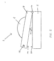
- Fig 2. shows a side view of printer 1 with lid 3 in a slightly raised position. This view better illustrates the shape of raised dome 5, latch 14 and guidepost 20. Paper roll 10 has been removed in this figure for clarity.
- Fig. 3 shows a top view of printer base 2 to more clearly illustrate the various components which are mounted on it. Lid 3 has been removed from the drawing for greater clarity. Paper holders 12 are mounted on both sides of the printer where they can be inserted into the core tube on both sides of the printer roll. The spacing between paper holders 12 is typically adjustable to accommodate various widths of paper. Platen 8 is a cylindrically-shaped roller which is long enough to accommodate the widest paper which the printer is capable of handling.
- Latch holes 16 are located in the base so that latches 14 will be inserted into these holes when the lid is closed.
- Latches 14 will typically have an L shape as shown in Fig. 2 and will typically be spring loaded so that they will swing into the center of latch holes 16 as the lid is being closed but will snap back underneath the edge of hole 16 when the lid is fully closed. These latches keep the lid securely attached to the base during normal operation.
- Guideposts 20 are also shown attached to base 2. When lid 3 is closed the front edge of printhead 6 will be pushed against the back edge of guideposts 20, as will be described in connection with Figs. 6 and 7, thus seating the printhead in its proper position.
- Fig. 4 shows a cross section taken along the line "A-A" of Fig. 3, including lid 3 which is shown in a slightly raised position. An edge view of paper 10 can also be seen passing between printhead 6 and platen 8, as it will be when a new roll of paper is being loaded into the printer. When lid 3 is completely closed, printhead 6 will press paper 10 against platen 8 and these components will all be in position for printing. This configuration is shown in Fig. 5, which shows the same cross section as Fig. 4, but with the lid closed.
- Platen 8 is a cylindrically shaped roller with suitable mounting at either end. During printing operations, platen 8 will rotate forward (counter clockwise in Figs. 4 and 5) to move paper tinder the printhead and out the front of the printer. The rotation of platen 8 can he controlled by conventional electronic components which may be located partially or completely within the printer.
- Printhead 6 is physically constrained within opening 28 of lid 3.
- Printhead 6 is limited in its downward travel by physical constraints which are typically at either end of printhead 6 and are therefore not shown in cross-section "A-A". Similar constraints may also be imposed to limit the travel of printhead 6 in the forward and backward directions. The use of such physical constraints is well known and is not described further.
- Printhead 6 also contains print elements 24 which are typically arranged in a single row along the length of the bottom of printhead 6.
- print elements 24 are composed of a single row of several hundred heating elements per inch. Each element can be individually heated to cause a dark spot to appear on temperature-sensitive paper. By alternately moving paper 10 forward one dot width at a time and heating selected elements, a two-dimensional image may be created on the paper. Depending on the complexity of the, associated electronics, this image may comprise numbers, letters, graphics, or other symbology. Other types of printhead technologies may also be used.
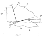
- Figs. 6 and 7 The precision alignment between printhead 6 and platen 8 is shown in Figs. 6 and 7.
- Printhead 6 descends in the direction of travel 38 indicated by the arrow.
- Direction of travel 38 is defined as the direction in which the printhead is moving immediately before the lid closes. This direction of travel actually forms an arc as lid 3 rotates around hinge 4. But the relevant portion of this arc, which in a preferred embodiment is approximately the last five degrees of travel before the lid closes, approximates a straight line and can be considered as such for a discussion of the alignment process.
- Direction of travel 38 is normal to plane 36.
- Plane 36 is an imaginary reference plane defined by 1) a line running along the axis of hinge 4, and 2) a point on the bottom of printhead 6 when lid 3 is closed.
- plane 36 appears horizontal when lid 3 is closed, but this would not be true if hinge 4 was placed higher or lower than shown, or if the printer were placed on a non-horizontal surface.
- hinge 4 and printhead 6 are physical components of the printer which don't depend on horizontal or vertical orientations, the direction of arrow 38 can always be correctly defined by these two elements.
- Alignment surface 32 of printhead 6 can be at an oblique angle of approximately 10 degrees from arrow 38. It might be more convenient to measure this as 80 degrees from plane 36, since plane 36 is defined by physical structure. In the embodiment shown, the entire printhead has been tilted forward. However, it is only important that the printhead alignment surface 32, in this case the front edge of printhead 6, be at an oblique angle. For reasons of manufacturing economy, a preferred embodiment uses the front surface of a rectangularly shaped printhead for alignment surface 32. However, other configurations could also be used, including a separate alignment structure that is rigidly attached to printhead 6.
- Alignment surface 34 of guidepost 20 is also tilted at an oblique angle with respect to direction of travel 38.
- alignment surface 34 is the back side of guidepost 20.
- printhead alignment surface 32 approaches guidepost alignment surface 34 along direction of travel 38.
- the aforementioned oblique angles of the two alignment surfaces 32 and 34 allows for a certain amount of tolerance in the approach positions between alignment surfaces 32 and 34, as measured by the amount that printhead 6 can be misaligned from front to back of the printer (left to right in Fig. 6) and still be correctly aligned when the lid is fully closed as shown in Fig. 7.
- surfaces 32 and 34 are flush with each other when the lid is fully closed, but while the lid is closing they can make first contact at any point after the bottom of printhead 6 passes the top of guidepost 20. As the lid is closed further, alignment surfaces 32 and 34 will slide against each other until they make hill contact as shown in Fig. 7. Surfaces 32 and 34 may also be non-parallel within a small range as they approach each other. In a preferred embodiment this range is about +/- 3 degrees. After first contact, as surfaces 32 and 34 slide against each other, they will be pushed together until they are flush, thus correcting for any prior non-parallel condition between them.
- the forward tilt of printhead 6 also causes printhead 6 to press paper 10 against platen 8 at point 40, which is several degrees forward from the point at which it would make contact if the bottom of printhead 6 were parallel to plane 36.
- Point 40 is actually a 'line' of contact, since it extends along the length of platen 8 and along the length of the bottom surface of printhead 6.
- Line of contact 40 is also the area of maximum pressure between the printhead, paper and platen. Best results are typically obtained if the print elements are moved away from this line by a prescribed distance.
- a preferred embodiment places the print elements 0.012 +/- 0.010 inches forward of the line of contact 40.
- the positioning of the print elements with respect to the platen can be controlled by controlling two primary dimensions: (1) the distance between print elements 24 and alignment surface 32 of printhead 6, and (2) the distance between alignment surface 34 of guidepost 20 and line of contact 40 on platen 8.
- the invention allows these dimensions to be controlled even with a certain amount of misalignment between printhead 6 and platen 8 prior to closing lid 3.
- This permissible misalignment allows various printer parts, such as base 2, lid 3 and hinge 4, to be made of relatively inexpensive materials with comparatively loose manufacturing tolerances. This permits the manufacture of a very inexpensive printer which is suitable for low cost uses such as label printers, adding machines, receipt printers and similar applications.
Landscapes
- Common Mechanisms (AREA)
- Electronic Switches (AREA)
- Handling Of Sheets (AREA)
Abstract
Description
- The invention relates to a print head mechanism in a printer. More particularly, it relates to a floating print head mechanism attached to the printer lid so that new paper can be loaded into the printer without the cumbersome procedure of threading the paper through the print mechanism.
- Printers are available in many different configurations utilizing a variety of technologies. The choice of the best features and technologies for a particular application depends on a number of factors including cost, print speed, print quality, durability and operating expenses. Regardless of the type of technology used, however, most printers have three elements in common: 1) a print head located on the side of the paper to be printed; 2) a platen located on the opposite side of the paper and providing physical support for the paper; and 3) a paper handling mechanism which moves the paper past the print head. In some cases the platen and the paper handling mechanism can be combined into a single roller which presses the paper against the print head and turns to advance the paper forward. This configuration is especially advantageous as it combines into a single item the functions of advancing the paper, providing a relatively hard surface against which the paper may he held, and maintaining the paper against the print head for a precision printing operation. Such rollers typically have a roller surface which is slightly compressible and which exhibits sufficient friction against the paper to move the paper with the required precision. Such rollers are well known in the printer industry and are not further described here.
- Some printers will print on cut-sheet paper, which requires a complicated and expensive mechanism to pick up each new sheet and position it correctly underneath the print head. However, many inexpensive printers print on a continuous roll of paper or on a continuous stack of fan-fold paper. The low cost obtained by avoiding the use of the costly sheet-handling mechanism makes this approach ideal for such devices as label printers, adding machines, and point-of-sale receipt printers.
- Maintaining print quality in roll-paper printers is usually accomplished by mounting the print head and the platen in a precise fixed relationship to each other, with the paper passing between them within a narrow space just large enough for the paper to pass through. However, when a new roll of paper must be inserted, this arrangement makes changing paper difficult. Not only must the user open the printer to access the paper space, but the user must also thread the new paper through the narrow space between the platen and the print head. This can be awkward and frustrating due to the cramped space allowed for the operator's hands, the difficulty of inserting new paper into such a small space, and the problem of getting the paper aligned once it has been inserted.
- This problem has been partially addressed in some conventional printers by providing print head mechanisms which can be moved away from the platen a small distance, thus slightly enlarging the space through which the paper must be threaded. This can be accomplished with a mechanism that raises the print head vertically upwards from the platen. It can also be accomplished by placing the print head on a short pivoting arm. However, maintaining accuracy dictates that the pivot arm be comparatively short and rigid, and that the pivot be relatively tight. A non-rigid arm can flex, thus introducing inaccuracy into the position of the print head. A long pivot arm amplifies manufacturing tolerances, thus requiring more expensive manufacturing techniques. Either approach adds components to the print head area, raising the cost and complexity of the resulting assembly. If the pivot joint is too loose, which is common with inexpensive pivot mechanisms, this too can create inaccuracy in the print head/platen alignment. Thus conventional printers require a tradeoff between low cost and the inconvenience of having to thread paper through a confined space whenever new paper is inserted in the printer. What is needed is a print head mechanism that allows new paper to be inserted easily and quickly without threading paper through a narrow space, and without the expense of additional complex close-tolerance components for enlarging that space.
- The invention includes a printer comprising a base with an attached lid having an open position and a closed position, a platen coupled to the base, a printhead assembly coupled to the lid, such that the printhead assembly is disposed proximate to the platen when the lid is in the closed position and is disposed apart from the platen when the lid is in the open position. The method of aligning the printhead with the platen in the printer comprises the steps of closing the printer lid onto the printer base, moving the printhead towards the platen when the lid is being closed, and aligning the printhead with the platen by contacting a printhead alignment edge with a guidepost alignment edge immediately before the lid closes.
-
- Fig. 1 is a perspective view of the printer of this invention;
- Fig. 2 is a side view of the printer of Fig. 1;
- Fig. 3 is a top view of the base of the printer of Fig. 1;
- Fig. 4 is a cross-sectional view of the print head and platen assemblies with the lid slightly open, taken along the line A-A of Fig. 3;
- Fig. 5 is a cross-sectional view of the print head and platen assemblies with the lid closed, taken along the line A-A of Fig. 3;
- Fig. 6 is a detailed view of the interaction between the printhead and the guideposts as the lid is closing; and
- Fig. 7 is a detailed view of the interaction between the printhead and the guideposts when the lid is closed.
-
- The invention solves the aforementioned problems with conventional printers by providing a print head which is located in the lid of the printer while the platen is located in the body of the printer. When the lid is opened to insert a new roll of paper, the print head and platen are completely separated. The leading edge of the paper can simply be pulled forward across the platen and the lid then closed to secure the paper and print head in their proper positions. Using the same hinge to raise the lid and raise the printhead reduces the parts count and cost of the printer. The required precision in the relative positions of the print head and platen are achieved through the use of a floating print head and precision guideposts which correctly position the print head when the lid is closed. Accurate positioning is relatively independent of the hinge and pivot arm materials. This permits the use of a comparatively loose hinge, located far from the printhead assembly. It also allows the supporting printer lid to be constructed of inexpensive materials with a degree of flexure that would otherwise be intolerable.
- The print head 'floats' in two dimensions, i.e., it is only loosely constrained by the surrounding lid assembly. Horizontal positioning is controlled by moving the print head down past the guideposts until an angled surface of the printhead contacts a similarly angled surface of each guidepost. Further movement causes the angled surfaces to slide against each other until they are flush. This causes the print head to be pushed firmly against the side of the guideposts. Since the guideposts are attached to the same assembly as the platen, the position of the guideposts with respect to the platen can be manufactured with a high degree of accuracy. Since the print head can also be constructed with precise dimensions, the physical contact between the guideposts and the print head accurately places the print head in proper horizontal alignment with the platen. Vertical positioning is controlled by spring loading the print head in the vertical direction. When the lid is closed this spring pushes the print head down against the paper and the platen. The force of the spring maintains a constant pressure by the print head against the paper, thus pressing the paper down against the platen. This pressure keeps the print head in constant contact with the paper for precision printing and keeps the paper in constant contact with the platen for controlled advancement of the paper whenever the platen rolls forward.
- As shown in Figs. 1-3, printer 1 includes a
lid 3 supporting a floatingprinthead 6, abase 2 supportingplaten 8 andalignment posts 20, and ahinge 4 for movably connectinglid 3 tobase 2. Printer 1 can also contain more conventional items, such asprint media 10, andlatches 14 which interact withlatch holes 16 to securelid 3 tobase 2 whenlid 3 is in the closed position. - Figs. 4-6 show the relationships between
printhead 6,platen 8, andguideposts 20. Spring-loadedprinthead 6 floats incavity 28. Whenlid 3 is closed and the bottom ofprinthead 6 is pushed againstplaten 8, the front edge ofprinthead 6 is seated against the back edge ofalignment posts 20, which accurately placesprinthead 6 in the proper position for printing. Placing the alignment edges ofprinthead 6 andalignment posts 20 at an angle to the direction of closure allows a certain amount of tolerance in the front-to-back positioning ofprinthead 6 relative toalignment posts 20 beforelid 3 is closed. This tolerance allows comparatively low-tolerance manufacturing in the construction oflid 3,base 2, andhinge 4, which can reduce the overall cost of the printer. - Fig. 1 shows a preferred embodiment of the printer with the lid raised to more clearly show the relevant components. Printer 1 has a
base 2 and alid 3 attached tobase 2 withhinge 4.Hinge 4 allowslid 3 to be opened as shown, exposing the internal parts and allowing the operator to gain access topaper roll 10.Paper roll 10 is supported by twopaper holders 12, one of which is obscured in Fig. 1 bypaper roll 10. These holders provide physical support to keeppaper roll 10 in place but allow paper roil 10 to rotate as it feeds paper into the printing mechanism at the front of the printer. To permit larger rolls of paper to be used,lid 3 has a raiseddome 5 which permits the lid to be closed even with a large roll of paper inserted in the printer. - When
lid 3 is closed it is secured in position bylatches 14 which are inserted into latch holes 16.Latches 14 can be standard spring-loaded latches which clasp the underside ofholes 16 when the lid is closed but can be released by turninglatch release 18, which is conveniently located on the side oflid 3.Printhead 6 is mounted inlid 3, whileguideposts 20 are attached tobase 2.Platen 8 is a roller assembly which is used to rollpaper 10 forward pastprinthead assembly 6.Platen 8 can be controlled by an electric motor and associated electronic components (not shown). - Fig 2. shows a side view of printer 1 with
lid 3 in a slightly raised position. This view better illustrates the shape of raiseddome 5, latch 14 andguidepost 20.Paper roll 10 has been removed in this figure for clarity. - Fig. 3 shows a top view of
printer base 2 to more clearly illustrate the various components which are mounted on it.Lid 3 has been removed from the drawing for greater clarity.Paper holders 12 are mounted on both sides of the printer where they can be inserted into the core tube on both sides of the printer roll. The spacing betweenpaper holders 12 is typically adjustable to accommodate various widths of paper.Platen 8 is a cylindrically-shaped roller which is long enough to accommodate the widest paper which the printer is capable of handling. - Latch holes 16 are located in the base so that latches 14 will be inserted into these holes when the lid is closed.
Latches 14 will typically have an L shape as shown in Fig. 2 and will typically be spring loaded so that they will swing into the center of latch holes 16 as the lid is being closed but will snap back underneath the edge ofhole 16 when the lid is fully closed. These latches keep the lid securely attached to the base during normal operation.Guideposts 20 are also shown attached tobase 2. Whenlid 3 is closed the front edge ofprinthead 6 will be pushed against the back edge ofguideposts 20, as will be described in connection with Figs. 6 and 7, thus seating the printhead in its proper position. - Fig. 4 shows a cross section taken along the line "A-A" of Fig. 3, including
lid 3 which is shown in a slightly raised position. An edge view ofpaper 10 can also be seen passing betweenprinthead 6 andplaten 8, as it will be when a new roll of paper is being loaded into the printer. Whenlid 3 is completely closed,printhead 6 will presspaper 10 againstplaten 8 and these components will all be in position for printing. This configuration is shown in Fig. 5, which shows the same cross section as Fig. 4, but with the lid closed. -
Platen 8 is a cylindrically shaped roller with suitable mounting at either end. During printing operations,platen 8 will rotate forward (counter clockwise in Figs. 4 and 5) to move paper tinder the printhead and out the front of the printer. The rotation ofplaten 8 can he controlled by conventional electronic components which may be located partially or completely within the printer. -
Printhead 6 is physically constrained within opening 28 oflid 3.Spring 22, which is preferably a leaf spring, exerts a downward force onprinthead 6.Printhead 6 is limited in its downward travel by physical constraints which are typically at either end ofprinthead 6 and are therefore not shown in cross-section "A-A". Similar constraints may also be imposed to limit the travel ofprinthead 6 in the forward and backward directions. The use of such physical constraints is well known and is not described further. -
Printhead 6 also containsprint elements 24 which are typically arranged in a single row along the length of the bottom ofprinthead 6. A preferred embodiment uses a thermal printhead in whichprint elements 24 are composed of a single row of several hundred heating elements per inch. Each element can be individually heated to cause a dark spot to appear on temperature-sensitive paper. By alternately movingpaper 10 forward one dot width at a time and heating selected elements, a two-dimensional image may be created on the paper. Depending on the complexity of the, associated electronics, this image may comprise numbers, letters, graphics, or other symbology. Other types of printhead technologies may also be used. - The precision alignment between
printhead 6 andplaten 8 is shown in Figs. 6 and 7. Referring to Fig. 6, aslid 3 closes,printhead 6 descends in the direction oftravel 38 indicated by the arrow. Direction oftravel 38 is defined as the direction in which the printhead is moving immediately before the lid closes. This direction of travel actually forms an arc aslid 3 rotates aroundhinge 4. But the relevant portion of this arc, which in a preferred embodiment is approximately the last five degrees of travel before the lid closes, approximates a straight line and can be considered as such for a discussion of the alignment process. Direction oftravel 38 is normal toplane 36.Plane 36 is an imaginary reference plane defined by 1) a line running along the axis ofhinge 4, and 2) a point on the bottom ofprinthead 6 whenlid 3 is closed. In the rectangular printer embodiment shown in Fig. 2,plane 36 appears horizontal whenlid 3 is closed, but this would not be true ifhinge 4 was placed higher or lower than shown, or if the printer were placed on a non-horizontal surface. However, sincehinge 4 andprinthead 6 are physical components of the printer which don't depend on horizontal or vertical orientations, the direction ofarrow 38 can always be correctly defined by these two elements. -
Alignment surface 32 ofprinthead 6 can be at an oblique angle of approximately 10 degrees fromarrow 38. It might be more convenient to measure this as 80 degrees fromplane 36, sinceplane 36 is defined by physical structure. In the embodiment shown, the entire printhead has been tilted forward. However, it is only important that theprinthead alignment surface 32, in this case the front edge ofprinthead 6, be at an oblique angle. For reasons of manufacturing economy, a preferred embodiment uses the front surface of a rectangularly shaped printhead foralignment surface 32. However, other configurations could also be used, including a separate alignment structure that is rigidly attached toprinthead 6. -
Alignment surface 34 ofguidepost 20 is also tilted at an oblique angle with respect to direction oftravel 38. In a preferred embodiment,alignment surface 34 is the back side ofguidepost 20. Whenlid 3 is being closed,printhead alignment surface 32 approachesguidepost alignment surface 34 along direction oftravel 38. The aforementioned oblique angles of the twoalignment surfaces printhead 6 passes the top ofguidepost 20. As the lid is closed further, alignment surfaces 32 and 34 will slide against each other until they make hill contact as shown in Fig. 7.Surfaces surfaces - In this manner, the interaction of the oblique angles of
printhead alignment surface 32 andguidepost alignment surface 34 not only compensates for linear misalignment ofprinthead 6, but also compensates for rotational misalignment ofprinthead 6. Since there are typically twoguideposts 20, one near either end of printhead 6 (see Figs. 1 and 3), both ends of the printhead will undergo (lie alignment process when the lid is closed. The amount of misalignment that can be corrected by this configuration varies somewhat with the size of the aforementioned oblique angle. Best results have been obtained with an angle of about 7 - 13 degrees whenguidepost alignment surface 34 is measured from direction oftravel 38, or about 77 - 83 degrees when measured fromplane 36. - As shown in Fig. 7, the forward tilt of
printhead 6 also causesprinthead 6 to presspaper 10 againstplaten 8 atpoint 40, which is several degrees forward from the point at which it would make contact if the bottom ofprinthead 6 were parallel to plane 36.Point 40 is actually a 'line' of contact, since it extends along the length ofplaten 8 and along the length of the bottom surface ofprinthead 6. However, in the edge view of Figs. 6 and 7, it appears as a point. The exact positioning of line ofcontact 40 with respect to vertical is not critical. However, the positioning ofprint elements 24 with respect to line ofcontact 40 is important. Line ofcontact 40 is also the area of maximum pressure between the printhead, paper and platen. Best results are typically obtained if the print elements are moved away from this line by a prescribed distance. A preferred embodiment places the print elements 0.012 +/- 0.010 inches forward of the line ofcontact 40. - As can be understood from the foregoing description, the positioning of the print elements with respect to the platen can be controlled by controlling two primary dimensions: (1) the distance between
print elements 24 andalignment surface 32 ofprinthead 6, and (2) the distance betweenalignment surface 34 ofguidepost 20 and line ofcontact 40 onplaten 8. The invention allows these dimensions to be controlled even with a certain amount of misalignment betweenprinthead 6 andplaten 8 prior to closinglid 3. This permissible misalignment allows various printer parts, such asbase 2,lid 3 andhinge 4, to be made of relatively inexpensive materials with comparatively loose manufacturing tolerances. This permits the manufacture of a very inexpensive printer which is suitable for low cost uses such as label printers, adding machines, receipt printers and similar applications. - The foregoing description is intended to be illustrative and not limiting. Obvious variations will occur to those of skill in the art. For instance, the platen could be placed in the lid while the printhead is placed in the base. This and other variations are intended to be encompassed by the invention, which is limited only by the spirit and scope of the appended claims.
Claims (14)
- A printer comprising:a base;a lid adapted to be coupled to the base, the lid having an open position and a closed position;a platen coupled to the base;a printhead assembly coupled to the lid; and
wherein the printhead assembly is disposed proximate to the platen when the lid is in the closed position and is disposed apart from the platen when the lid is in the open position. - The printer of claim 1, wherein the platen includes a cylindrical roller rotatably coupled to the base.
- The printer of claim 1, wherein the base includes a guidepost.
- The printer of claim 3, wherein the printhead assembly is in a predetermined position with respect to the guidepost when the lid is in the closed position.
- The printer of claim 4, wherein the printhead assembly is in physical contact with the guidepost when the lid is in the closed position.
- The printer of claim 1, wherein the printhead assembly includes a spring for biasing the printhead assembly towards the platen when the lid is in the closed position.
- The printer of claim 6, wherein the spring is a leaf spring.
- The printer of claim 1, wherein the printhead assembly includes a plurality of print elements arranged in a linear pattern.
- The printer of claim 8, wherein the plurality of print elements are a plurality of thermal print elements.
- The printer of claim 1, wherein:the lid is movably coupled to the base with a hinge having an axis;the hinge axis and a point on the printhead define a plane;the printhead includes a printhead alignment edge approximately at an oblique angle from the plane; andthe base includes a guidepost having a guidepost alignment edge at the oblique angle from the plane when the lid is in the closed position.
- The printer of claim 10, wherein:the oblique angle is between about 77 degrees and about 83 degrees.
- The printer of claim 1, wherein:the platen is cylindrical;the printhead and the platen form a line of contact therebetween when the lid is closed; andthe printhead includes print elements disposed a predetermined distance from the line of contact.
- The printer of claim 12, wherein the predetermined distance is between about 2 and about 22 thousandths of an inch.
- A method of aligning a printhead with a platen in a printer, comprising the steps of:closing a printer lid onto a printer base;moving a printhead towards a platen when the lid is being closed;contacting a printhead alignment edge with a guidepost alignment edge before the lid closes; andaligning the printhead with the platen by the step of contacting.
Applications Claiming Priority (2)
| Application Number | Priority Date | Filing Date | Title |
|---|---|---|---|
| US189557 | 1998-11-11 | ||
| US09/189,557 US6068415A (en) | 1998-11-11 | 1998-11-11 | Printer with floating print head with alignment surfaces to position printhead |
Publications (2)
| Publication Number | Publication Date |
|---|---|
| EP1018435A2 true EP1018435A2 (en) | 2000-07-12 |
| EP1018435A3 EP1018435A3 (en) | 2000-10-11 |
Family
ID=22697847
Family Applications (1)
| Application Number | Title | Priority Date | Filing Date |
|---|---|---|---|
| EP99203604A Withdrawn EP1018435A3 (en) | 1998-11-11 | 1999-11-02 | Printer with floating print head |
Country Status (2)
| Country | Link |
|---|---|
| US (1) | US6068415A (en) |
| EP (1) | EP1018435A3 (en) |
Cited By (3)
| Publication number | Priority date | Publication date | Assignee | Title |
|---|---|---|---|---|
| GB2391514A (en) * | 2002-08-06 | 2004-02-11 | Markem Tech Ltd | Printing method including a print head mounted on a structure by a coupling fastener wherein a resilient spacer is placed between the structure and the head |
| EP1455515A1 (en) * | 2003-03-07 | 2004-09-08 | Sagem SA | Fax machine with a housing having two half-shells |
| DE112011101291B4 (en) | 2010-04-12 | 2024-09-05 | Zebra Technologies Corporation | Media processing device with advanced features for loading and unloading media and printing films |
Families Citing this family (11)
| Publication number | Priority date | Publication date | Assignee | Title |
|---|---|---|---|---|
| US6494631B1 (en) | 2000-09-29 | 2002-12-17 | Z.I.H. Corp. | Printer with ribbon fold out mechanism |
| US6736561B2 (en) * | 2001-01-24 | 2004-05-18 | Xerox Corporation | Apparatus and method for the prevention of trailing edge deletion in image forming systems |
| JP2003237118A (en) * | 2002-02-21 | 2003-08-27 | Sii P & S Inc | Thermal printer |
| US6937260B2 (en) * | 2003-12-23 | 2005-08-30 | Xerox Corporation | Alignment mechanism for direct marking printheads and a method for aligning printheads in a printer |
| US7273262B2 (en) | 2004-06-23 | 2007-09-25 | Hewlett-Packard Development Company, L.P. | System with alignment information |
| US9296214B2 (en) | 2004-07-02 | 2016-03-29 | Zih Corp. | Thermal print head usage monitor and method for using the monitor |
| US7245312B2 (en) * | 2005-06-10 | 2007-07-17 | Zih Corp. | Thermal printer with quick-release printhead assembly |
| KR100699478B1 (en) * | 2005-06-17 | 2007-03-26 | 삼성전자주식회사 | Print head assembly and image forming apparatus having the same |
| US20070147938A1 (en) * | 2005-12-13 | 2007-06-28 | Zih Corp. | Printer encoder adapted for positioning aboard a mobile unit |
| JP4252106B1 (en) * | 2008-02-20 | 2009-04-08 | 株式会社サトー知識財産研究所 | Thermal printer |
| US9061527B2 (en) * | 2012-12-07 | 2015-06-23 | Datamax-O'neil Corporation | Thermal printer with single latch, adjustable media storage and centering assemblies and print assembly |
Citations (4)
| Publication number | Priority date | Publication date | Assignee | Title |
|---|---|---|---|---|
| US4641980A (en) * | 1984-10-02 | 1987-02-10 | Fujitsu Limited | Printer with pivotable print head attached to medium carrier moveable through a casing opening |
| DE4005810A1 (en) * | 1990-02-23 | 1991-08-29 | Siemens Ag | Thermal transfer printer with precision retension of print head - has stop frame positioning of print element line and roller axis for automatic position maintenance |
| EP0463595A2 (en) * | 1990-06-26 | 1992-01-02 | Seiko Epson Corporation | Line thermal printer |
| US5694159A (en) * | 1994-03-25 | 1997-12-02 | Kabushiki Kaisha Sato | Thermal printer |
Family Cites Families (6)
| Publication number | Priority date | Publication date | Assignee | Title |
|---|---|---|---|---|
| EP0194528B1 (en) * | 1985-03-15 | 1991-11-06 | Hitachi, Ltd. | Printer having a thermal head |
| US4718785A (en) * | 1987-02-12 | 1988-01-12 | Eastman Kodak Company | Compliant head loading mechanism for thermal printer |
| US5139351A (en) * | 1987-10-22 | 1992-08-18 | Ricoh Company, Ltd. | Thermal recording apparatus having a movable platen roller |
| JP2557714B2 (en) * | 1989-12-14 | 1996-11-27 | 株式会社新盛インダストリーズ | Label printer device |
| US5304007A (en) * | 1991-05-05 | 1994-04-19 | Gulton Industries, Inc. | Thermal printhead balanced spring mount |
| JP3309038B2 (en) * | 1995-09-29 | 2002-07-29 | アンリツ株式会社 | Thermal head holding structure |
-
1998
- 1998-11-11 US US09/189,557 patent/US6068415A/en not_active Ceased
-
1999
- 1999-11-02 EP EP99203604A patent/EP1018435A3/en not_active Withdrawn
Patent Citations (4)
| Publication number | Priority date | Publication date | Assignee | Title |
|---|---|---|---|---|
| US4641980A (en) * | 1984-10-02 | 1987-02-10 | Fujitsu Limited | Printer with pivotable print head attached to medium carrier moveable through a casing opening |
| DE4005810A1 (en) * | 1990-02-23 | 1991-08-29 | Siemens Ag | Thermal transfer printer with precision retension of print head - has stop frame positioning of print element line and roller axis for automatic position maintenance |
| EP0463595A2 (en) * | 1990-06-26 | 1992-01-02 | Seiko Epson Corporation | Line thermal printer |
| US5694159A (en) * | 1994-03-25 | 1997-12-02 | Kabushiki Kaisha Sato | Thermal printer |
Cited By (5)
| Publication number | Priority date | Publication date | Assignee | Title |
|---|---|---|---|---|
| GB2391514A (en) * | 2002-08-06 | 2004-02-11 | Markem Tech Ltd | Printing method including a print head mounted on a structure by a coupling fastener wherein a resilient spacer is placed between the structure and the head |
| GB2391514B (en) * | 2002-08-06 | 2006-03-22 | Markem Tech Ltd | Printing apparatus and methods |
| US7273323B2 (en) | 2002-08-06 | 2007-09-25 | Markem Technologies Limited | Printing apparatus and methods |
| EP1455515A1 (en) * | 2003-03-07 | 2004-09-08 | Sagem SA | Fax machine with a housing having two half-shells |
| DE112011101291B4 (en) | 2010-04-12 | 2024-09-05 | Zebra Technologies Corporation | Media processing device with advanced features for loading and unloading media and printing films |
Also Published As
| Publication number | Publication date |
|---|---|
| US6068415A (en) | 2000-05-30 |
| EP1018435A3 (en) | 2000-10-11 |
Similar Documents
| Publication | Publication Date | Title |
|---|---|---|
| US6068415A (en) | Printer with floating print head with alignment surfaces to position printhead | |
| US6612762B1 (en) | Printer | |
| JP4492125B2 (en) | Roll sheet holder and tape printer | |
| JPS61501905A (en) | Printer with recording media thickness compensation mechanism | |
| USRE38473E1 (en) | Printer with floating print head with alignment surfaces to position printhead | |
| US8328443B2 (en) | Printer and roll paper holding mechanism | |
| JPH0578499B2 (en) | ||
| US4655625A (en) | Single station printer for printing on plural record media | |
| US4718783A (en) | Thermal printer | |
| JP7128773B2 (en) | printer | |
| JP4595089B2 (en) | Print positioning mechanism and printer | |
| JP2683202B2 (en) | Printing device | |
| JPH08502001A (en) | Platen for label printer | |
| US6239825B1 (en) | Thermal printing apparatus | |
| JP2004034305A (en) | Printer | |
| JP2006021497A (en) | Printer | |
| JP3790480B2 (en) | Thermal printer | |
| CN220722926U (en) | Sheet medium processing device | |
| JP7128772B2 (en) | printer | |
| JP2007301910A (en) | Printer | |
| JP4074720B2 (en) | Tag printer | |
| JP4087649B2 (en) | Mounting structure of thermal recording head | |
| JP3386103B2 (en) | Carriage for impact dot printer | |
| EP1892111B1 (en) | Image generating apparatus | |
| JPS62152773A (en) | Printing gap adjusting mechanism for printer |
Legal Events
| Date | Code | Title | Description |
|---|---|---|---|
| PUAI | Public reference made under article 153(3) epc to a published international application that has entered the european phase |
Free format text: ORIGINAL CODE: 0009012 |
|
| AK | Designated contracting states |
Kind code of ref document: A2 Designated state(s): DE FR GB |
|
| AX | Request for extension of the european patent |
Free format text: AL;LT;LV;MK;RO;SI |
|
| PUAL | Search report despatched |
Free format text: ORIGINAL CODE: 0009013 |
|
| AK | Designated contracting states |
Kind code of ref document: A3 Designated state(s): AT BE CH CY DE DK ES FI FR GB GR IE IT LI LU MC NL PT SE |
|
| AX | Request for extension of the european patent |
Free format text: AL;LT;LV;MK;RO;SI |
|
| 17P | Request for examination filed |
Effective date: 20001215 |
|
| AKX | Designation fees paid |
Free format text: DE FR GB |
|
| RAP1 | Party data changed (applicant data changed or rights of an application transferred) |
Owner name: ZIH CORP. |
|
| 17Q | First examination report despatched |
Effective date: 20040811 |
|
| RAP1 | Party data changed (applicant data changed or rights of an application transferred) |
Owner name: ZIH CORPORATION |
|
| RAP1 | Party data changed (applicant data changed or rights of an application transferred) |
Owner name: ZIH CORPORATION |
|
| STAA | Information on the status of an ep patent application or granted ep patent |
Free format text: STATUS: THE APPLICATION IS DEEMED TO BE WITHDRAWN |
|
| 18D | Application deemed to be withdrawn |
Effective date: 20060912 |