EP1018211B1 - Method and apparatus for compensating a line synchronous generator - Google Patents
Method and apparatus for compensating a line synchronous generator Download PDFInfo
- Publication number
- EP1018211B1 EP1018211B1 EP98907428A EP98907428A EP1018211B1 EP 1018211 B1 EP1018211 B1 EP 1018211B1 EP 98907428 A EP98907428 A EP 98907428A EP 98907428 A EP98907428 A EP 98907428A EP 1018211 B1 EP1018211 B1 EP 1018211B1
- Authority
- EP
- European Patent Office
- Prior art keywords
- generator
- exciter
- stage
- rotor
- windings
- Prior art date
- Legal status (The legal status is an assumption and is not a legal conclusion. Google has not performed a legal analysis and makes no representation as to the accuracy of the status listed.)
- Expired - Lifetime
Links
- 230000001360 synchronised effect Effects 0.000 title claims abstract description 36
- 238000000034 method Methods 0.000 title claims description 18
- 238000004804 winding Methods 0.000 claims abstract description 143
- 238000000819 phase cycle Methods 0.000 claims description 6
- 238000010586 diagram Methods 0.000 description 15
- 239000013598 vector Substances 0.000 description 15
- 239000000446 fuel Substances 0.000 description 10
- 230000000694 effects Effects 0.000 description 7
- 230000006698 induction Effects 0.000 description 7
- 239000003990 capacitor Substances 0.000 description 5
- 238000006073 displacement reaction Methods 0.000 description 5
- 230000002411 adverse Effects 0.000 description 3
- 230000001965 increasing effect Effects 0.000 description 3
- 238000004519 manufacturing process Methods 0.000 description 3
- 230000007246 mechanism Effects 0.000 description 3
- XLYOFNOQVPJJNP-UHFFFAOYSA-N water Substances O XLYOFNOQVPJJNP-UHFFFAOYSA-N 0.000 description 3
- 238000006243 chemical reaction Methods 0.000 description 2
- 230000010363 phase shift Effects 0.000 description 2
- 230000008569 process Effects 0.000 description 2
- 238000011084 recovery Methods 0.000 description 2
- 239000004215 Carbon black (E152) Substances 0.000 description 1
- 230000006978 adaptation Effects 0.000 description 1
- 238000002485 combustion reaction Methods 0.000 description 1
- 230000005611 electricity Effects 0.000 description 1
- 238000005516 engineering process Methods 0.000 description 1
- 230000005284 excitation Effects 0.000 description 1
- 239000002803 fossil fuel Substances 0.000 description 1
- ZZUFCTLCJUWOSV-UHFFFAOYSA-N furosemide Chemical compound C1=C(Cl)C(S(=O)(=O)N)=CC(C(O)=O)=C1NCC1=CC=CO1 ZZUFCTLCJUWOSV-UHFFFAOYSA-N 0.000 description 1
- 239000007789 gas Substances 0.000 description 1
- 229930195733 hydrocarbon Natural products 0.000 description 1
- 150000002430 hydrocarbons Chemical class 0.000 description 1
- 230000001939 inductive effect Effects 0.000 description 1
- 238000003780 insertion Methods 0.000 description 1
- 230000037431 insertion Effects 0.000 description 1
- 230000016507 interphase Effects 0.000 description 1
- 230000005405 multipole Effects 0.000 description 1
- 238000005457 optimization Methods 0.000 description 1
- 230000003071 parasitic effect Effects 0.000 description 1
- 230000009467 reduction Effects 0.000 description 1
- 230000004044 response Effects 0.000 description 1
- 238000010998 test method Methods 0.000 description 1
- 230000035899 viability Effects 0.000 description 1
- 239000002918 waste heat Substances 0.000 description 1
Images


Classifications
-
- H—ELECTRICITY
- H02—GENERATION; CONVERSION OR DISTRIBUTION OF ELECTRIC POWER
- H02K—DYNAMO-ELECTRIC MACHINES
- H02K19/00—Synchronous motors or generators
- H02K19/16—Synchronous generators
- H02K19/38—Structural association of synchronous generators with exciting machines
-
- H—ELECTRICITY
- H02—GENERATION; CONVERSION OR DISTRIBUTION OF ELECTRIC POWER
- H02K—DYNAMO-ELECTRIC MACHINES
- H02K19/00—Synchronous motors or generators
- H02K19/16—Synchronous generators
- H02K19/26—Synchronous generators characterised by the arrangement of exciting windings
-
- H—ELECTRICITY
- H02—GENERATION; CONVERSION OR DISTRIBUTION OF ELECTRIC POWER
- H02P—CONTROL OR REGULATION OF ELECTRIC MOTORS, ELECTRIC GENERATORS OR DYNAMO-ELECTRIC CONVERTERS; CONTROLLING TRANSFORMERS, REACTORS OR CHOKE COILS
- H02P9/00—Arrangements for controlling electric generators for the purpose of obtaining a desired output
- H02P9/42—Arrangements for controlling electric generators for the purpose of obtaining a desired output to obtain desired frequency without varying speed of the generator
-
- H—ELECTRICITY
- H02—GENERATION; CONVERSION OR DISTRIBUTION OF ELECTRIC POWER
- H02P—CONTROL OR REGULATION OF ELECTRIC MOTORS, ELECTRIC GENERATORS OR DYNAMO-ELECTRIC CONVERTERS; CONTROLLING TRANSFORMERS, REACTORS OR CHOKE COILS
- H02P2101/00—Special adaptation of control arrangements for generators
- H02P2101/10—Special adaptation of control arrangements for generators for water-driven turbines
-
- H—ELECTRICITY
- H02—GENERATION; CONVERSION OR DISTRIBUTION OF ELECTRIC POWER
- H02P—CONTROL OR REGULATION OF ELECTRIC MOTORS, ELECTRIC GENERATORS OR DYNAMO-ELECTRIC CONVERTERS; CONTROLLING TRANSFORMERS, REACTORS OR CHOKE COILS
- H02P2101/00—Special adaptation of control arrangements for generators
- H02P2101/15—Special adaptation of control arrangements for generators for wind-driven turbines
Definitions
- the present invention relates generally to an electrical generator, and more particularly, to an improved induction generator referenced to an AC power source.
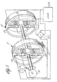
- the induction generator of FIG. 1 includes two stages, an exciter stage 10 and a generator stage 12.
- the exciter stage 10 includes an exciter stator 14 connected to an AC power source 16 and an exciter rotor 18 disposed for rotary advancement by a local power source 19.
- the generator stage 12 includes a generator rotor 20, connected for common rotation with the exciter rotor 18, and a generator stator 22. The windings of the exciter rotor 18 and the generator rotor 20 are connected together, but wound in opposite directions.
- the generator stator 22 is connected to a load 23.
- the exciter rotor 18 is rotated by the local power source 19 within the rotating magnetic field developed by the exciter stator 14.
- the induced signal frequency at the output of the exciter rotor 18 is equal to the summation of the angular rate of the local power source 19 plus the frequency of the AC power source 16.
- the generator rotor 20 is rotated within the generator stator 22, the inverse connection to the exciter rotor 14 causes the angular rate produced by the local power source 19 to be subtracted out. The result being an induced voltage at the output of the generating stator 22 equal in rate to the frequency of the AC power source.
- phase angle alignment be easily achieved even for exciter and generator components wound in opposite directions or with phases that start in different slots on the core with relation to the keyway.
- French Patent Specification No 2 425 171 discloses a line synchronous generator having an exciter stage and a generator stage.
- the generator stage has a pair of poles each having windings inversely connected to corresponding windings of the exciter pair of poles for cancelling the electrical frequency induced by rotation of the exciter and generator rotors.
- US Patent No 5,418,446 discloses a line synchronous generator having a rotor connected for rotation with exciter and generator rotors.
- a stator has an interior portion with the rotor rotationally mounted therein.
- a method for determining phase alignment of a three-phase line synchronous generator comprising an exciter stage having an exciter stator and an exciter rotor, one of said exciter stator and exciter rotor having a primary winding and the other one of said exciter stator and exciter rotors having a primary winding and the other one of said generator stator and generator rotor having first, second and third secondary phase windings, and a generator stage having a generator rotor and a generator stator, one of said generator stator and generator rotor having first, second and third secondary phase windings, the method comprising the steps of: connecting the primary windings of the exciter and generator stages to a three-phase AC power source, said AC power source having a line voltage equal to Vm; connecting a first secondary phase winding of the exciter stage to a first secondary phase winding of the generator stage; finding a voltage of substantially 2Vm between a secondary
- the proper phase angle alignment of the first, second and third phase windings of the secondary windings are determined by connecting the primary windings of the exciter and generator stages to the AC power source having a line voltage Vm, and connecting the first secondary phase winding of the exciter stage to the first secondary phase winding of the generator stage. Then, the voltage between the second secondary phase winding of the exciter stage and the second secondary phase winding of the generator stage is confirmed to be approximately 2Vm, and the voltage between the third secondary phase winding of the exciter stage and the third secondary phase winding of the generator stage is confirmed to be approximately 2Vm.
- the voltage between the second secondary phase winding of the exciter stage and the third secondary phase winding of the generator stage is confirmed to be approximately ⁇ 3Vm
- the voltage between the third secondary phase winding of the exciter stage and the second secondary phase winding of the generator stage is confirmed to be approximately ⁇ 3Vm.
- the line synchronous generator is configured with an exciter rotor disposed for rotary advancement by an external power source.
- the exciter rotor includes a pair of poles each having a winding for connecting across the AC power source.
- the exciter stator mounted for rotation on an interior portion of the exciter stator, also has a pair of poles each having a winding.
- the generator rotor mounted for common rotation with the exciter rotor, has a pair of poles each having a winding for connection across the AC power source.
- the generator stage has an interior portion with the generator rotor rotationally mounted therein.
- the generator stator has a pair of poles each having a winding inversely connected to the corresponding windings on the exciter pole pair for cancelling the electrical frequency induced by the of the rotation of the exciter and generator rotors.
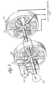
- the three-phase line synchronous generator includes two stages, an exciter stage 24 and a generator stage 26.
- the exciter stage 24 includes an exciter stator 28 having three electromagnetic pole pairs. Each pole pair has a primary winding connected across a different phase of an AC power source 30.
- An exciter rotor 32 mounted for rotation within the interior of the exciter stator 28, also includes three electromagnetic pole pairs each wound with a secondary winding.
- the exciter rotor 32 is disposed for rotary advancement by a local power source 33.
- the generator stage 26 includes a generator rotor 34 connected for common rotation with the exciter rotor 32 inside the interior of a generator stator 38.
- the generator rotor 34 also includes three electromagnetic pole pairs each wound with a secondary winding.
- the secondary windings of the generator rotor are inversely connected to the secondary windings of the exciter rotor 32 to effect electrical cancellation of the frequency induced by the angular rotation of the local power source.
- the generator stator 38 is connected to the AC power source 30.
- the rotors of the exciter and generator stages are connected to the AC power source, and the three-phase windings of the exciter and generator stators are connected for electrical cancellation.
- an exciter rotor 52 disposed for rotary advancement by a local power source 53, has three electromagnetic pole pairs each with a primary winding connected across a different phase of the AC power source 54.
- the exciter stage 56 also includes an exciter stator 72 with three electromagnetic pole pairs wound with secondary windings.
- the generator stage 64 includes a generator stator 74 with three electromagnetic pole pairs wound with secondary windings.
- the secondary windings of the exciter stator 72 are inversely connected to the secondary windings of the generator stator 74 to effect electrical cancellation of the frequency induced by the angular rotation of the local power source.
- the generator rotor 75 connected for common rotation with the exciter rotor 52, is connected to the AC power source 54.
- stator primary machine i.e., stators connected to the AC power source.
- the present invention is not limited to stator primary machines, and that all described embodiments and test procedures are equally applicable to rotor primary machines, i.e., rotors connected to the AC power source.
- the line synchronous generator may be expanded to include redundant components. Specifically, a third redundant stage comprising a rotor 78 on the common shaft 80 and a stator 76 may be left unconnected. The terminals T001, T002 and T003 may then be connected in replacement for the terminals T1, T2 and T3 or T01, T02 and T03, in the event that the exciter or generator stage fails.
- the exciter stator 28 is excited by the AC power source 30 which creates a revolving magnetic field at an angular rate equal to the frequency of the AC power source 30.
- the exciter rotor 32 is rotated by the local power source 33 within the rotating magnetic field developed by the exciter stator 28.
- the induced signal frequency at the output of the exciter rotor 32 is equal to the summation of the angular rate of the local power source 33 plus the frequency of the AC power source 30.
- the generator rotor 34 is rotated within the generator stator 38, the inverse connection to the exciter rotor 32 causes the angular rate produced by the local power source 33 to be subtracted out.
- the stator windings are connected to the corresponding phases of the AC power source.
- the proper phase angle between the rotor windings is then established by the interconnection process.
- the rotor windings must be connected such that the voltage induced by angular rotation in each excitor rotor winding has an equal but opposite polarity than the voltage induced in the generator rotor winding to which it is connected.
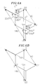
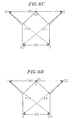
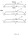
- FIGS. 5 and 6 Vector diagrams provide a useful mechanism for illustrating how the interconnections between the second windings can be ascertained. As shown in FIGS. 5 and 6, only three possible interconnections between the rotor windings results in a 180 0 phase shift between the each secondary winding connection as shown in FIGS. 5A-5C, each exciter rotor winding is shifted 180 0 with respect to its corresponding generator rotor winding. For example, consider FIG. 5B.
- the same phase relationships hold true for the secondary connections shown by the vector diagrams in FIGS. 5A and 5C.
- vector diagrams are also useful for establishing test parameters for determining the proper interconnections between the rotor windings during the manufacturing process.
- the voltages between the remaining open windings will consist of two pairs at two times the line voltage (2Vm) and two pairs at ⁇ 3 times the line voltage ( ⁇ 3 Vm) which is proven by the geometric relationship between the phases. For example, the voltages induced in the open windings in FIG.
- the voltage across T2-T03 is the resultant of an oblique triangle defined by sides T1-T03, T01-T2, and T2-T03.
- classic three-phase electrical theory identifies the angles as shown on Figure 5B.
- the voltage between T3-T02. Therefore, with proper alignment, the voltage will be one pair of terminals at two times line voltage and one pair of terminals at ⁇ 3 times the line voltage.
- a methodology of interconnecting the rotor windings can be ascertained which significantly reduces the manufacturing cost while increasing product yield.
- the method for determining the proper interconnections in a stator primary machine requires the connection of a pair of rotor windings and then finding two remaining pairs of substantially identical voltages between the rotor windings.
- FIG. 7A the secondary windings are shown ready for test.
- the exciter and generator stators are connected to an AC power source.
- the line voltages induced should be equal if the two sets of rotor windings are alike: turns, pitch, wire size, connection, etc.
- the interphase voltage is 90 volts.
- the connection could be wye (star) as shown, or delta, or one of each.
- a terminal from each rotor winding is joined by a connecting jumper.
- Either the primary or secondary could be the rotor or stator, but they must be the same part.
- the other half of the synchronous generator must also be configured as a rotor primary machine.
- a jumper wire is placed across a terminal for each rotor winding.
- the jumper wire is then removed and placed across another terminal pair.
- T1 - T02 156 volts
- T1 - T03 180 volts
- FIGS. 5A-5C confirms the proper interconnection of the rotor windings. From the vector diagrams 5A-5C it can be seen that the rotor windings having a voltage of 2Vm, or 180 volts should be connected together.
- the proper interconnections of the rotor windings are shown in FIG. 7B with T1 connected to T03 and T3 connected to T02.
- the terminals should be renumbered.
- electrical compensation may then be inserted between each pair of the three-phase windings.
- resistors and capacitors can be inserted between the respective windings to expand the dynamic operating range of the device without the necessity of continual phase angle adjustments between the exciter and generator stages.
- electrical compensation may be inserted in the primary windings of the stators.
- compensation networks 76, 78 and 80 effect the winding interconnection described above.
- Network 76 includes a resistor 82, in parallel with a capacitor 84
- network 78 comprises a resistor 88 in parallel connection with a capacitor 90
- network 80 comprises a resistor 94, in parallel connection with a capacitor 96. It has been found that by increasing the resistance of resistors 82, 88, and 94 from approximately 0 ohms to about 5.8 ohms, the dynamic range expressed in ratio of both the power factor and efficiency are substantially increased.
- FIG. 9 shows the expanded range of the device using utilizing resistors to achieve the desired results for tailored applications.
- the output curve is shown for a 15 kW, 4 pole, 60 Hz three-phase line synchronizing generator.
- phase angle between the generator and exciter stages is the phase angle between the generator and exciter stages.
- the angular position of the exciter stator, exciter generator, generator rotor or generator stator can be advanced or retarded to optimize performance.
- Optimal loading is a function of the exciter phase angle and rotor rpm. As the RPM increases substantially above "synchronous speed", the phase angle range necessary to meet maximum generator load narrows significantly. Thus, through manipulation of the phase angle of the exciter stage relative to the generator stage, complete control over loading is achieved.
- a responsive and accurate device must be employed to adequately provide phase angle optimization when variable speed prime movers are used.
- FIG. 10 illustrates the output power of a 6 pole, 25 kW, 480 volt, 60 Hz stator primary machine coupled to a 75 horsepower DC variable speed motor at different phase angles. The power output is shown at four different phase angles between the exciter and generator magnetic field.
- the generator stator field is tapped and compared with the AC source frequency by a control mechanism to provide a phase error signal to a servo motor.
- This servo motor positions the exciter stator to optimize generator loading, a function of the phase difference that results from changes in shaft speed.
- the accuracy and response of the servo motor and its control mechanism are critical to optimize generator loading. Because servo motor control technology is sufficiently advanced, accurate exciter induction compensation can be provided in virtually all electrical generation applications.
- the phase angle may be set during the interconnection process of the rotor windings.
- FIG. 11 a vector diagram is shown representing the phase relationships - of the rotor windings with proper interconnection to effect electrical cancellation but with a 15° phase angle misalignment between the exciter and generator stages.
- the test represented in FIG. 10 is performed with T1 connected to T01.
- the voltage between terminals T2 - T02 and T3 -T03 are each 178 volts, which is close enough to 180 volts to satisfy one of the required pairs.
- the voltages between the remaining terminals are not close enough to the 156 volts to satisfy the second required pair. However, if the voltages are averaged, the result is 155 volts which is close to the desired voltage. This indicates improper phase angle between the exciter stage and the generator stage.
- either the exciter stator, the exciter rotor, the generator stator or the generator rotor can be physically rotated on its axis until the voltages between T2 and T03 and the voltages between T3 and T02 each read 155 volts. In this case, from the vector diagram of FIG. 8, it can be seen that a 15 0 electrical phase shift will result in optimal performance.
- phase angle correction can be performed by altering the windings of either the exciter rotor, exciter stator, generator rotor or the generator stator.
- the optimum phase angle can be achieved without physically shifting the rotors or stators, but winding them offset. If slots on the generator portion are numbered 1 to 36, for example, we start the generator group in slot 1, and the exciter's group is started in slot 2 or 3, to get the phase angle as desired.
- the described embodiments provide an important solution that allows the rotational speed to vary substantially over traditional machinery limits while remaining self-synchronizing.
- the active controls are simplified to those necessary for safety purposes.
- the machinery speed maximum limits may be enhanced with simple active control of passive devices.
- any local power source which allows for a minimum speed and exceeds the parasitic losses of the device may be effectively used to supply the utility grid.
- Such adaptation of local alternative power sources has a major potential for resolving the present energy shortage with minimum adverse ecological consequences.
- the present invention satisfies an immediate need for a three-phase line synchronous generator with proper phasing having a constant frequency and voltage output at variable shaft speeds.
- This three-phase line synchronous generator may be embodied in other specific forms and can be used with a variety of fuel sources, such as windmills, wind turbines, water wheels, water turbines, internal combustion engines, solar powered engines, steam turbine, without departing from the spirit or essential attributes of the present invention. It is therefore desired that the described embodiments be considered in all respects as illustrative and not restrictive, reference being made to the appended claims rather than the foregoing description to indicate the scope of the invention.
Landscapes
- Engineering & Computer Science (AREA)
- Power Engineering (AREA)
- Control Of Eletrric Generators (AREA)
- Synchronous Machinery (AREA)
- Emergency Protection Circuit Devices (AREA)
- Control Of Stepping Motors (AREA)
Applications Claiming Priority (3)
| Application Number | Priority Date | Filing Date | Title |
|---|---|---|---|
| US3772397P | 1997-02-07 | 1997-02-07 | |
| US37723P | 1997-02-07 | ||
| PCT/US1998/002651 WO1998037623A1 (en) | 1997-02-07 | 1998-02-06 | Method and apparatus for compensating a line synchronous generator |
Publications (3)
| Publication Number | Publication Date |
|---|---|
| EP1018211A1 EP1018211A1 (en) | 2000-07-12 |
| EP1018211A4 EP1018211A4 (en) | 2001-07-11 |
| EP1018211B1 true EP1018211B1 (en) | 2006-08-30 |
Family
ID=21895943
Family Applications (1)
| Application Number | Title | Priority Date | Filing Date |
|---|---|---|---|
| EP98907428A Expired - Lifetime EP1018211B1 (en) | 1997-02-07 | 1998-02-06 | Method and apparatus for compensating a line synchronous generator |
Country Status (11)
| Country | Link |
|---|---|
| US (1) | US6072303A (enExample) |
| EP (1) | EP1018211B1 (enExample) |
| JP (1) | JP4101884B2 (enExample) |
| CN (1) | CN1082746C (enExample) |
| AT (1) | ATE338374T1 (enExample) |
| AU (1) | AU6323698A (enExample) |
| BR (1) | BR9807825B1 (enExample) |
| CA (1) | CA2283943C (enExample) |
| DE (1) | DE69835757T2 (enExample) |
| TR (1) | TR199902416T2 (enExample) |
| WO (1) | WO1998037623A1 (enExample) |
Families Citing this family (31)
| Publication number | Priority date | Publication date | Assignee | Title |
|---|---|---|---|---|
| US5346436A (en) * | 1993-09-23 | 1994-09-13 | Borg-Warner Automotive, Inc. | Air vent for hydraulic chain tensioner |
| US20040041480A1 (en) * | 1997-02-07 | 2004-03-04 | Nickoladze Leo G. | Method and apparatus for compensating a line synchronous generator |
| US20020180296A1 (en) * | 1998-02-27 | 2002-12-05 | Foundation Gni, Ltd. | Variable speed constant frequency motor |
| US9506405B2 (en) | 1998-04-03 | 2016-11-29 | Rockwell Collins Control Technologies, Inc. | Apparatus and method for controlling power generation system |
| US6171055B1 (en) * | 1998-04-03 | 2001-01-09 | Aurora Flight Sciences Corporation | Single lever power controller for manned and unmanned aircraft |
| SE512784C2 (sv) * | 1998-04-21 | 2000-05-15 | Hoeganaes Ab | Induktionsmaskinstator |
| US6218813B1 (en) * | 1999-09-30 | 2001-04-17 | Rockwell Technologies, Llc | Cross current compensation system and method |
| US6285168B1 (en) * | 1999-09-30 | 2001-09-04 | Rockwell Automation Technologies, Inc. | Reactive droop compensation system and method |
| TWI296875B (en) * | 2002-04-25 | 2008-05-11 | Step motor with multiple stators | |
| US6909263B2 (en) * | 2002-10-23 | 2005-06-21 | Honeywell International Inc. | Gas turbine engine starter-generator exciter starting system and method including a capacitance circuit element |
| US20070024147A1 (en) * | 2003-08-18 | 2007-02-01 | Hirzel Andrew D | Selective alignment of stators in axial airgap electric devices comprising low-loss materials |
| US7071657B2 (en) * | 2004-03-04 | 2006-07-04 | Raven Technology, Llc | Method and apparatus for the production of power frequency alternating current directly from the output of a single-pole type generator |
| US7135829B1 (en) | 2005-08-10 | 2006-11-14 | Innovative Power Solutions, Llc | Methods and apparatus for controlling a motor/generator |
| US7116073B1 (en) * | 2005-08-10 | 2006-10-03 | Innovative Power Solutions, Llc | Methods and apparatus for controlling a motor/generator |
| US20070126406A1 (en) * | 2005-08-31 | 2007-06-07 | Prevailing Energy, Inc. | Turbine with Configurable Generator Circuit |
| US7425771B2 (en) * | 2006-03-17 | 2008-09-16 | Ingeteam S.A. | Variable speed wind turbine having an exciter machine and a power converter not connected to the grid |
| CN101401294B (zh) * | 2006-03-17 | 2013-04-17 | 英捷电力技术有限公司 | 具有激励器设备和不连接至电网的功率变换器的变速风机 |
| US7576443B2 (en) * | 2006-12-15 | 2009-08-18 | General Electric Company | Method and apparatus for generating electric power |
| NZ556760A (en) * | 2007-07-26 | 2008-12-24 | Auckland Uniservices Ltd | An electric generator |
| US20100019711A1 (en) * | 2008-07-28 | 2010-01-28 | Orchid Radio Co., Ltd. | Motor with controllable rotor-pole magnetic intensity |
| WO2010059983A2 (en) * | 2008-11-21 | 2010-05-27 | Preus Robert W | Wind turbine |
| CA2748095A1 (en) | 2009-01-16 | 2010-07-22 | Core Wind Power, Inc. | Segmented stator for an axial field device |
| US8198743B2 (en) * | 2009-09-11 | 2012-06-12 | Honeywell International, Inc. | Multi-stage controlled frequency generator for direct-drive wind power |
| GB2476238B (en) * | 2009-12-15 | 2015-11-18 | Ge Oil & Gas Uk Ltd | Underwater power generation |
| US9154024B2 (en) | 2010-06-02 | 2015-10-06 | Boulder Wind Power, Inc. | Systems and methods for improved direct drive generators |
| US8339019B1 (en) | 2012-07-30 | 2012-12-25 | Boulder Wind Power, Inc. | Structure for an electromagnetic machine having compression and tension members |
| US8736133B1 (en) | 2013-03-14 | 2014-05-27 | Boulder Wind Power, Inc. | Methods and apparatus for overlapping windings |
| US10177620B2 (en) | 2014-05-05 | 2019-01-08 | Boulder Wind Power, Inc. | Methods and apparatus for segmenting a machine |
| AT516489A1 (de) * | 2014-10-31 | 2016-05-15 | Ge Jenbacher Gmbh & Co Og | Kraftanlage |
| JP6451990B2 (ja) * | 2015-04-02 | 2019-01-16 | 株式会社デンソー | 回転電機 |
| US10224848B2 (en) * | 2017-01-30 | 2019-03-05 | Pratt & Whitney Canada Corp. | Method and system for synchronizing generators |
Family Cites Families (15)
| Publication number | Priority date | Publication date | Assignee | Title |
|---|---|---|---|---|
| US2829333A (en) * | 1955-04-22 | 1958-04-01 | Sperry Gyroscope Co Ltd | Constant-frequency alternating-current generators |
| US2854617A (en) * | 1957-01-24 | 1958-09-30 | Siegler Corp | Frequency control apparatus for alternators |
| GB1448990A (en) * | 1972-12-22 | 1976-09-08 | Nat Res Dev | Roatary and linear electric machines |
| US4019104A (en) * | 1974-03-26 | 1977-04-19 | Parker Louis W | Variable speed induction motor |
| FR2425171A1 (fr) * | 1978-05-03 | 1979-11-30 | Ams Sa | Procede d'obtention d'un courant alternatif de frequence fixe a partir d'une machine tournante de vitesse quelconque et generatrice electrique pour sa mise en oeuvre |
| US4305001A (en) * | 1979-02-26 | 1981-12-08 | Lima Electric Company, Inc. | Constant frequency alternator |
| US4229689A (en) * | 1979-11-05 | 1980-10-21 | Nickoladze Leo G | AC Synchronized generator |
| US4472673A (en) * | 1982-04-15 | 1984-09-18 | Energia Andina Ltda. | Rotating electric machine with speed/frequency control |
| US4625160A (en) * | 1984-12-17 | 1986-11-25 | Sundstrand Corporation | Variable speed constant frequency generating system |
| US4701691A (en) * | 1985-05-14 | 1987-10-20 | Nickoladze Leo G | Synchronous generators |
| US5587643A (en) * | 1988-07-12 | 1996-12-24 | Heller Dejulio Corporation | Rotary induction machine having control of secondary winding impedance |
| US5274291A (en) * | 1990-01-08 | 1993-12-28 | Clarke Patrick W | Rotary transformer with multiple angularly adjustable stators |
| DE69100430T2 (de) * | 1990-05-26 | 1994-04-28 | Satake Eng Co Ltd | Synchron-Induktionsmotor mit Doppelstator. |
| US5525894A (en) * | 1992-08-03 | 1996-06-11 | Heller-Dejulio Corporation | Rotary induction generator adapted to be driven by a prime mover for generating electric power |
| US5418446A (en) * | 1993-05-10 | 1995-05-23 | Hallidy; William M. | Variable speed constant frequency synchronous electric power generating system and method of using same |
-
1998
- 1998-02-06 CA CA002283943A patent/CA2283943C/en not_active Expired - Fee Related
- 1998-02-06 CN CN988038285A patent/CN1082746C/zh not_active Expired - Fee Related
- 1998-02-06 TR TR1999/02416T patent/TR199902416T2/xx unknown
- 1998-02-06 BR BRPI9807825-9A patent/BR9807825B1/pt not_active IP Right Cessation
- 1998-02-06 EP EP98907428A patent/EP1018211B1/en not_active Expired - Lifetime
- 1998-02-06 AT AT98907428T patent/ATE338374T1/de not_active IP Right Cessation
- 1998-02-06 AU AU63236/98A patent/AU6323698A/en not_active Abandoned
- 1998-02-06 DE DE69835757T patent/DE69835757T2/de not_active Expired - Lifetime
- 1998-02-06 WO PCT/US1998/002651 patent/WO1998037623A1/en not_active Ceased
- 1998-02-06 JP JP53671998A patent/JP4101884B2/ja not_active Expired - Fee Related
-
1999
- 1999-06-22 US US09/338,002 patent/US6072303A/en not_active Expired - Lifetime
Also Published As
| Publication number | Publication date |
|---|---|
| CA2283943C (en) | 2009-02-03 |
| AU6323698A (en) | 1998-09-09 |
| ATE338374T1 (de) | 2006-09-15 |
| US6072303A (en) | 2000-06-06 |
| EP1018211A4 (en) | 2001-07-11 |
| BR9807825A (pt) | 2000-03-08 |
| WO1998037623A1 (en) | 1998-08-27 |
| JP4101884B2 (ja) | 2008-06-18 |
| DE69835757D1 (de) | 2006-10-12 |
| CA2283943A1 (en) | 1998-08-27 |
| EP1018211A1 (en) | 2000-07-12 |
| CN1082746C (zh) | 2002-04-10 |
| DE69835757T2 (de) | 2007-09-20 |
| JP2001519996A (ja) | 2001-10-23 |
| CN1251696A (zh) | 2000-04-26 |
| BR9807825B1 (pt) | 2011-04-19 |
| TR199902416T2 (xx) | 2000-03-21 |
Similar Documents
| Publication | Publication Date | Title |
|---|---|---|
| EP1018211B1 (en) | Method and apparatus for compensating a line synchronous generator | |
| US20130181561A1 (en) | Method and apparatus for compensating a line synchronous generator | |
| US8085004B2 (en) | Generator with quadrature AC excitation | |
| US7915869B2 (en) | Single stage starter/generator with rotor quadrature AC excitation | |
| US7514806B2 (en) | Engine start system with quadrature AC excitation | |
| Chan et al. | A novel single-phase self-regulated self-excited induction generator using a three-phase machine | |
| US6628005B2 (en) | Single speed turbine generator for different power system output frequencies in power generation systems and associated methods | |
| US6943462B2 (en) | Ring generator for a wind power installation | |
| US20070013250A1 (en) | Variable speed constant frequency motor | |
| US20030052565A1 (en) | Method and apparatus for compensating a line synchronous generator | |
| US7868594B2 (en) | Generating unit and method for producing a current with a predetermined network frequency | |
| JP6833743B2 (ja) | ブラシレス同期発電機 | |
| KR100980063B1 (ko) | 3상 라인 동기 발전기의 위상 정렬을 결정하는 방법 | |
| Reddy et al. | Modeling of Dual Excited Synchronous Generator with slip frequency excitation | |
| MXPA99007213A (en) | Method and apparatus for compensating a line synchronous generator | |
| Amuhaya et al. | Permanent magnet wind generator with double excitation for smart grids | |
| PRADHAN et al. | LEARNING MATERIAL | |
| Nair | Inductor generators for alternative energy schemes | |
| Guo | Steady-State Performance of Asynchronized Synchronous Machines | |
| Band et al. | Mathematical and Simulation Approach for Synchronization of Two Asynchronous Grids | |
| Kapp et al. | Discussion on “Polyphase commutator machines and their application” | |
| Machines II | Short questions and answers EE1251 Electrical Machines II | |
| Daniels | The basis of operation of electromagnetic machines |
Legal Events
| Date | Code | Title | Description |
|---|---|---|---|
| PUAI | Public reference made under article 153(3) epc to a published international application that has entered the european phase |
Free format text: ORIGINAL CODE: 0009012 |
|
| 17P | Request for examination filed |
Effective date: 19990907 |
|
| AK | Designated contracting states |
Kind code of ref document: A1 Designated state(s): AT BE CH DE DK ES FI FR GB GR IE IT LI LU MC NL PT SE |
|
| RAP1 | Party data changed (applicant data changed or rights of an application transferred) |
Owner name: THE ESTATE OF LEO G. NICKOLADZE (DECEASED) |
|
| RIC1 | Information provided on ipc code assigned before grant |
Free format text: 7H 02P 9/00 A, 7H 02K 17/10 B, 7H 02K 19/26 B |
|
| RIC1 | Information provided on ipc code assigned before grant |
Free format text: 7H 02P 9/00 A, 7H 02K 17/10 B, 7H 02K 17/44 B, 7H 02K 19/26 B, 7H 02P 9/42 B |
|
| A4 | Supplementary search report drawn up and despatched |
Effective date: 20010525 |
|
| AK | Designated contracting states |
Kind code of ref document: A4 Designated state(s): AT BE CH DE DK ES FI FR GB GR IE IT LI LU MC NL PT SE |
|
| 17Q | First examination report despatched |
Effective date: 20040611 |
|
| GRAP | Despatch of communication of intention to grant a patent |
Free format text: ORIGINAL CODE: EPIDOSNIGR1 |
|
| GRAS | Grant fee paid |
Free format text: ORIGINAL CODE: EPIDOSNIGR3 |
|
| GRAA | (expected) grant |
Free format text: ORIGINAL CODE: 0009210 |
|
| AK | Designated contracting states |
Kind code of ref document: B1 Designated state(s): AT BE CH DE DK ES FI FR GB GR IE IT LI LU MC NL PT SE |
|
| PG25 | Lapsed in a contracting state [announced via postgrant information from national office to epo] |
Ref country code: NL Free format text: LAPSE BECAUSE OF FAILURE TO SUBMIT A TRANSLATION OF THE DESCRIPTION OR TO PAY THE FEE WITHIN THE PRESCRIBED TIME-LIMIT Effective date: 20060830 Ref country code: IT Free format text: LAPSE BECAUSE OF FAILURE TO SUBMIT A TRANSLATION OF THE DESCRIPTION OR TO PAY THE FEE WITHIN THE PRESCRIBED TIME-LIMIT;WARNING: LAPSES OF ITALIAN PATENTS WITH EFFECTIVE DATE BEFORE 2007 MAY HAVE OCCURRED AT ANY TIME BEFORE 2007. THE CORRECT EFFECTIVE DATE MAY BE DIFFERENT FROM THE ONE RECORDED. Effective date: 20060830 Ref country code: FI Free format text: LAPSE BECAUSE OF FAILURE TO SUBMIT A TRANSLATION OF THE DESCRIPTION OR TO PAY THE FEE WITHIN THE PRESCRIBED TIME-LIMIT Effective date: 20060830 Ref country code: BE Free format text: LAPSE BECAUSE OF FAILURE TO SUBMIT A TRANSLATION OF THE DESCRIPTION OR TO PAY THE FEE WITHIN THE PRESCRIBED TIME-LIMIT Effective date: 20060830 Ref country code: AT Free format text: LAPSE BECAUSE OF FAILURE TO SUBMIT A TRANSLATION OF THE DESCRIPTION OR TO PAY THE FEE WITHIN THE PRESCRIBED TIME-LIMIT Effective date: 20060830 |
|
| REG | Reference to a national code |
Ref country code: GB Ref legal event code: FG4D |
|
| REG | Reference to a national code |
Ref country code: CH Ref legal event code: EP |
|
| REG | Reference to a national code |
Ref country code: IE Ref legal event code: FG4D |
|
| REF | Corresponds to: |
Ref document number: 69835757 Country of ref document: DE Date of ref document: 20061012 Kind code of ref document: P |
|
| PG25 | Lapsed in a contracting state [announced via postgrant information from national office to epo] |
Ref country code: DK Free format text: LAPSE BECAUSE OF FAILURE TO SUBMIT A TRANSLATION OF THE DESCRIPTION OR TO PAY THE FEE WITHIN THE PRESCRIBED TIME-LIMIT Effective date: 20061130 |
|
| PG25 | Lapsed in a contracting state [announced via postgrant information from national office to epo] |
Ref country code: ES Free format text: LAPSE BECAUSE OF FAILURE TO SUBMIT A TRANSLATION OF THE DESCRIPTION OR TO PAY THE FEE WITHIN THE PRESCRIBED TIME-LIMIT Effective date: 20061211 |
|
| REG | Reference to a national code |
Ref country code: SE Ref legal event code: TRGR |
|
| REG | Reference to a national code |
Ref country code: CH Ref legal event code: NV Representative=s name: BRAUNPAT BRAUN EDER AG |
|
| PG25 | Lapsed in a contracting state [announced via postgrant information from national office to epo] |
Ref country code: PT Free format text: LAPSE BECAUSE OF FAILURE TO SUBMIT A TRANSLATION OF THE DESCRIPTION OR TO PAY THE FEE WITHIN THE PRESCRIBED TIME-LIMIT Effective date: 20070206 |
|
| PG25 | Lapsed in a contracting state [announced via postgrant information from national office to epo] |
Ref country code: MC Free format text: LAPSE BECAUSE OF NON-PAYMENT OF DUE FEES Effective date: 20070228 |
|
| NLV1 | Nl: lapsed or annulled due to failure to fulfill the requirements of art. 29p and 29m of the patents act | ||
| EN | Fr: translation not filed | ||
| PLBE | No opposition filed within time limit |
Free format text: ORIGINAL CODE: 0009261 |
|
| STAA | Information on the status of an ep patent application or granted ep patent |
Free format text: STATUS: NO OPPOSITION FILED WITHIN TIME LIMIT |
|
| 26N | No opposition filed |
Effective date: 20070531 |
|
| PG25 | Lapsed in a contracting state [announced via postgrant information from national office to epo] |
Ref country code: GR Free format text: LAPSE BECAUSE OF FAILURE TO SUBMIT A TRANSLATION OF THE DESCRIPTION OR TO PAY THE FEE WITHIN THE PRESCRIBED TIME-LIMIT Effective date: 20061201 Ref country code: FR Free format text: LAPSE BECAUSE OF FAILURE TO SUBMIT A TRANSLATION OF THE DESCRIPTION OR TO PAY THE FEE WITHIN THE PRESCRIBED TIME-LIMIT Effective date: 20070511 |
|
| PG25 | Lapsed in a contracting state [announced via postgrant information from national office to epo] |
Ref country code: FR Free format text: LAPSE BECAUSE OF FAILURE TO SUBMIT A TRANSLATION OF THE DESCRIPTION OR TO PAY THE FEE WITHIN THE PRESCRIBED TIME-LIMIT Effective date: 20060830 |
|
| PG25 | Lapsed in a contracting state [announced via postgrant information from national office to epo] |
Ref country code: LU Free format text: LAPSE BECAUSE OF NON-PAYMENT OF DUE FEES Effective date: 20070206 |
|
| PGFP | Annual fee paid to national office [announced via postgrant information from national office to epo] |
Ref country code: IE Payment date: 20150210 Year of fee payment: 18 Ref country code: DE Payment date: 20150210 Year of fee payment: 18 Ref country code: CH Payment date: 20150213 Year of fee payment: 18 |
|
| PGFP | Annual fee paid to national office [announced via postgrant information from national office to epo] |
Ref country code: GB Payment date: 20150211 Year of fee payment: 18 Ref country code: SE Payment date: 20150212 Year of fee payment: 18 |
|
| REG | Reference to a national code |
Ref country code: DE Ref legal event code: R119 Ref document number: 69835757 Country of ref document: DE |
|
| REG | Reference to a national code |
Ref country code: CH Ref legal event code: PL |
|
| REG | Reference to a national code |
Ref country code: SE Ref legal event code: EUG |
|
| GBPC | Gb: european patent ceased through non-payment of renewal fee |
Effective date: 20160206 |
|
| PG25 | Lapsed in a contracting state [announced via postgrant information from national office to epo] |
Ref country code: LI Free format text: LAPSE BECAUSE OF NON-PAYMENT OF DUE FEES Effective date: 20160229 Ref country code: CH Free format text: LAPSE BECAUSE OF NON-PAYMENT OF DUE FEES Effective date: 20160229 |
|
| PG25 | Lapsed in a contracting state [announced via postgrant information from national office to epo] |
Ref country code: SE Free format text: LAPSE BECAUSE OF NON-PAYMENT OF DUE FEES Effective date: 20160207 |
|
| REG | Reference to a national code |
Ref country code: IE Ref legal event code: MM4A |
|
| PG25 | Lapsed in a contracting state [announced via postgrant information from national office to epo] |
Ref country code: GB Free format text: LAPSE BECAUSE OF NON-PAYMENT OF DUE FEES Effective date: 20160206 Ref country code: IE Free format text: LAPSE BECAUSE OF NON-PAYMENT OF DUE FEES Effective date: 20160206 Ref country code: DE Free format text: LAPSE BECAUSE OF NON-PAYMENT OF DUE FEES Effective date: 20160901 |