EP1017239A2 - Verfahren zur Unterdrückung von Artefakten in einem elektronischen Bild, das aus einem blocktransformationskodierten Bild dekodiert worden ist - Google Patents
Verfahren zur Unterdrückung von Artefakten in einem elektronischen Bild, das aus einem blocktransformationskodierten Bild dekodiert worden ist Download PDFInfo
- Publication number
- EP1017239A2 EP1017239A2 EP99204114A EP99204114A EP1017239A2 EP 1017239 A2 EP1017239 A2 EP 1017239A2 EP 99204114 A EP99204114 A EP 99204114A EP 99204114 A EP99204114 A EP 99204114A EP 1017239 A2 EP1017239 A2 EP 1017239A2
- Authority
- EP
- European Patent Office
- Prior art keywords
- pixels
- image
- boundary
- pixel
- block
- Prior art date
- Legal status (The legal status is an assumption and is not a legal conclusion. Google has not performed a legal analysis and makes no representation as to the accuracy of the status listed.)
- Withdrawn
Links
Images


Classifications
-
- H—ELECTRICITY
- H04—ELECTRIC COMMUNICATION TECHNIQUE
- H04N—PICTORIAL COMMUNICATION, e.g. TELEVISION
- H04N19/00—Methods or arrangements for coding, decoding, compressing or decompressing digital video signals
- H04N19/50—Methods or arrangements for coding, decoding, compressing or decompressing digital video signals using predictive coding
- H04N19/503—Methods or arrangements for coding, decoding, compressing or decompressing digital video signals using predictive coding involving temporal prediction
- H04N19/51—Motion estimation or motion compensation
- H04N19/527—Global motion vector estimation
-
- H—ELECTRICITY
- H04—ELECTRIC COMMUNICATION TECHNIQUE
- H04N—PICTORIAL COMMUNICATION, e.g. TELEVISION
- H04N19/00—Methods or arrangements for coding, decoding, compressing or decompressing digital video signals
- H04N19/85—Methods or arrangements for coding, decoding, compressing or decompressing digital video signals using pre-processing or post-processing specially adapted for video compression
- H04N19/86—Methods or arrangements for coding, decoding, compressing or decompressing digital video signals using pre-processing or post-processing specially adapted for video compression involving reduction of coding artifacts, e.g. of blockiness
Definitions
- the invention relates generally to the field of image processing and, more particularly, to removing artifacts resulting from block-transform coded images.
- DCT discrete cosine transform
- a digital representation of an image is divided into a plurality of non-overlapping, contiguous 8x8 blocks of pixel data.
- Each non-overlapping 8x8 pixel block of image data is then transformed, via the DCT, from a pixel representation space into a DCT representation space.
- Each transformed block of image data is comprised of one DC coefficient and 63 AC coefficients.
- the DC coefficient represents the average brightness of the block and the AC coefficients represent the spatial frequency information in the block.
- the DC and AC coefficients for each block are quantized and encoded into a bit-stream prior to any transmission to another computer workstation.
- Quantization in effect, introduces numerical loss by mapping a range of coefficient values to one value, which mapping is referred to hereinafter as a quantization level.
- Encoding assigns a binary code to the resulting set of quantized values.
- the bit-stream is decoded and dequantized to reconstruct the set of dequantized coefficient values. These dequantized coefficients are subsequently transformed back into the pixel representation space via an inverse discrete cosine transform (IDCT), as is well known in the art.
- IDCT inverse discrete cosine transform
- the number of bits generated by the compression process corresponds, in part, to the number of quantization levels used in the quantization.
- coarse quantization will generate a fewer number of bits than a less coarse quantization.
- coarse quantization introduces undesirable artifacts at the decoding workstation.
- Coarse quantization may increase the disparity between the DC coefficients of neighboring blocks, and it may destroy AC coefficient information within a block. This results in artifacts that are oftentimes visually more objectionable in regions of slowly varying intensity.
- an image region is said to be “low detail” if it contains relatively low spatial frequency information, as is the case in regions of slowly varying intensity. Additionally, an image region is said to be “boundary” if it is near a low detail region.
- AC prediction A standard technique for reducing blocking artifacts is known as AC prediction, such as that referenced by Mitchell, J.L. and W.B. Pennebaker "JPEG ENHANCEMENTS" Still Image Data Compression Standard 1993, page 261-265, and is applied at the decompression workstation.
- AC prediction for low frequency AC coefficients is formed using dequantized DC coefficients from the current block and its eight nearest neighbor blocks.
- the AC predicted coefficient values for the block replace the zero-quantized AC coefficient values (i.e., those that have been quantized to zero) prior to transforming the image back into the pixel representation space.
- One shortcoming of this technique is that the AC predicted coefficients replace the zero-quantized AC coefficient values regardless of the other spatial frequency content of the block. This has the undesirable tendency of visually smoothing out high frequency image detail, and of introducing low frequency AC information which has no effect in reducing the disparity of dequantized DC coefficients between neighboring blocks.
- An adaptive method for reducing blocking artifacts is disclosed in an European Patent Application 0585573A2 by De Garido et. al.
- An adaptive AC Predictor is based on a prescribed activity measure of the current image block and its eight nearest neighbor blocks. This technique, unlike the above-described method, does not introduce low frequency information via AC prediction in high spatial frequency areas; thus, high spatial frequency and texture information which is indicative of high activity blocks is preserved.
- This adaptive AC prediction technique still has the disadvantage of not reducing the disparity of the dequantized DC coefficients between neighboring blocks in low activity image areas.
- the invention resides in a method for preventing artifacts in an electronic image decoded from a block-transform coded representation of an image, the method comprising the steps of: (a) receiving blocks of the electronic image decoded from the transform-coded representation of the image; (b) determining whether a portion of the decoded image contains low detail pixels; (c) determining boundary pixels as pixels within a predetermined area of a predetermined number of low detail pixels; (d) based on step 1(c), filtering the boundary pixels with one of a plurality of directionally-oriented smoothing filters for obtaining one or more boundary replacement pixel values; and (e) reconstructing the image by replacing one or more pixels in the boundary with one or more of the boundary replacement pixel values.
- the present invention has the following advantage of identifying regions containing low spatial frequency information and boundary regions near them, and of performing a unique smoothing operation according to the identified content.
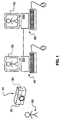
- a digital camera 10 such as a "KODAK” DC 50, includes a charge-coupled device, CCD (not shown), for receiving incident light through a lens 20, and for converting the incident light into an electronic, digital representation of an image 25 that is contained within the incident light, as is well known in the photographic industry.
- the CCD transfers the electronic representation of the image to a personal computer card (PCC) 30 for storing the image for later retrieval.
- PCC personal computer card
- JPEG compression software which is stored on a memory module (not shown) of the camera 10 is used for compressing the digital representation of the image received from the CCD. Such compression is desirable for limiting the amount of memory necessary for storing the digital representation of the image on the PCC 30.
- the PCC 30 is inserted into a local computer or workstation 40 for permitting the representation of the image to be decompressed and viewed on a monitor 50 that is electrically connected to the local computer 40.
- the digital representation of the image 25, which is still in compressed form may be transmitted to another remote computer or workstation 60 where it is decompressed for viewing on a monitor 70, printing by a printer (not shown) or further processing by a remote user.
- a software program of the present invention is stored on the remote computer 50 for processing the decompressed digital representation of the image to reduce the occurrence of artifacts for permitting such viewing.
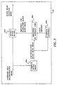
- Figs. 2 there is shown a graphical illustration of the software program of the present invention for reducing the occurrence of artifacts in the image when it is reconstructed.
- this software receives the image in a form that has been compressed by lossy JPEG compressor, and subsequently decompressed by a decoder.
- the decoder dequantizes the incoming data, and performs an inverse discrete cosine transform operation so that the resulting reconstructed digital image includes 8x8 blocks of pixel values; the decoding operation is well known in the art and will not be discussed in detail herein.
- the reconstructed digital image is input into a block mean smoother 80 that performs an adjustment on the mean value of the image blocks for facilitating the deblocking process.
- the block mean smoother 80 first computes 80a the mean pixel value of each 8x8 block, each of these mean pixel values being referred to hereinafter as a mean block value.
- a mean block value For purposes of illustration, if the standard JPEG reconstructed image is 512x512 pixels, the low resolution, block mean image will be an array of 64x64 mean pixel values.
- each particular mean block value is then calculated 80b using a 3x3 array centered on the particular mean block value, as illustrated in Fig.4 where n 1-9 represent mean block values 85 with the 3x3 array being centered on mean block value n 5 .
- n 1-9 represent mean block values 85 with the 3x3 array being centered on mean block value n 5 .
- blocks near the edge of the image, so that the block mean array 85 cannot be centered entirely within the image are left unmodified. Those skilled in the are will realize there are other options for handling these border blocks. Referring back to Figs.
- b(m,n) indicate a block mean value
- i,j and m,n indicate the block index within the 3x3 array and the block index within the entire image, respectively
- weighting windows can certainly be used if desired as those skilled in the art can determine.
- An alternative window is as follows:
- the pixels in the corresponding block of the full resolution image are adjusted 80d so that their mean is equal to the adjusted mean b ⁇ ( m , n ).
- the mean value of a block is replaced by a local average when the local variance of the block means is less than a threshold.
- This hard thresholding might not be robust in all cases. It is, therefore, suggested that a slightly modified method for block mean smoothing be used that might prove more robust at the cost of extra computation.
- the block mean b ( m , n ) is found and then ⁇ 2 / b as in Equation (1) and b ⁇ ( m , n ) as in Equation (3) are computed.
- ⁇ 2 / b ( m , n ) increases, ⁇ ( m , n ) approaches 1 and b ⁇ ( m , n ) tends toward b ( m , n ), leaving the block mean essentially unchanged.
- the block mean smoothing can be effectively implemented in the DCT domain, prior to pixel reconstruction.
- the low resolution image would then be composed simply of the DC coefficients of each block. Since the DC coefficient is 8 times the mean value of the block, the threshold parameter T b should be scaled by 64.
- the modified pixels in this low resolution image become the new DC coefficients for the corresponding block prior to reconstruction of the pixel values.
- the block mean adjusted image is input into a gradient computation and pixel labeling processor 90 for defining which pixels are low detail, and which pixels are boundary pixels.
- the labels of the pixels are used to determine what type of smoothing, if any, is performed on a given pixel.
- Gradient values 90a and 90b are calculated for each pixel value as follows.
- the separable 1-D coefficients of this kernel are 1 31.634 [0.243, 0.451, 0.702, 0.915, 1.00, 0.915, 0.702, 0.451, 0.243].
- the resulting smoothed image will hereinafter be referred to as the smoothed gradient image, G s ( m , n ).
- the smoothing reduces the noise in the gradient estimates of Equation (8) and additionally serves to diffuse large gradients so that nearby pixels are not subsequently labeled low detail, which will be described hereinbelow.
- a pixel in the block mean adjusted image at position ( m , n ) is labeled low detail 90d if G s ( m , n ) ⁇ T g , where T g is a threshold, preferably 4.5521, although those skilled in the art may alter this threshold depending on the desired result.
- Boundary pixels are identified from the low detail map as follows.
- a 19 x 19 square window centered on every '0' in the low detail map i.e., those pixels not labeled low detail
- this window covers more than one low detail pixel (more than a single '1' in the low detail map)
- the pixel on which the window is centered is labeled a boundary pixel 90e.
- the result is a binary image where a '1' indicates that the corresponding pixel is a boundary pixel and where all other pixels are labeled a '0'.
- the resulting map is referred to hereinafter as the "boundary pixel map.” .
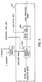
- pixels in the block mean adjusted image are smoothed 100 according to their labels obtained from the gradient computation and pixel labeling processor 90.
- the boundary pixels are smoothed 100a using one of four 5 x 5 directionally oriented filters whose kernels are given below:
- Kernels oriented in more directions can also be employed with modifications to the decision process described below. This directional smoothing of the boundary pixels tends to preserve the integrity of edges while reducing edge artifacts such as ringing and/or staircasing.
- the kernel used for smoothing is determined from the gradients G v ( m , n ) and G h ( m , n ) using the following decision process:
- T dir is 5. It facilitates understanding to note that the particular filter used depends upon the slope of the edge of the boundary.
- the low detail pixels are smoothed 100b with a large kernel, lowpass filter.
- the separable 1-D coefficients of this kernel are 1 28.915 ⁇ [0.070, 0.182, 0.384, 0.653, 0.899, 1.00, 0.899, 0.653, 0.384, 0.182, 0.070].
- the 11 x 11 size is chosen so that the kernel always extends significantly across block boundaries, thereby decreasing blocking effects. Again it is noted that other kernels can be employed, as those skilled in the art should find apparent.
- the output of the pixel smoothing stage 100 is the final processed image.
- a pseduocode program for performing the steps of the present invention (on a monochrome image or the luminance channel of a color image) is contained in appendix A.
- the operation of the present invention has been described for a monochrome image or for a single (luminance) channel of a color image.
- the operation of the present invention on the other (chrominance) channels is as follows.
- One simple, computationally efficient solution would be to apply the current invention to only the luminance channel and leave the other chrominance channels unchanged.
- Another straightforward implementation would be to apply the current invention on first the luminance channel, as has been described, and then to repeat on each of the other chrominance channels separately. In the preferred embodiment, however, the current invention is applied first to the luminance channel and the resulting information is used to apply the invention to the remaining chrominance channels. as follows.
- the means of the corresponding blocks in the chrominance channels are adjusted as well.
- the pixel labels from the luminance channel i.e., the low detail map and the boundary pixel map
- the directions selected for filtering the boundary pixels in the luminance channel are used to determine the direction for smoothing the boundary pixels in the chrominance channels.
- the low detail and boundary pixels in the chrominance channels are smoothed appropriately.
Landscapes
- Engineering & Computer Science (AREA)
- Multimedia (AREA)
- Signal Processing (AREA)
- Compression Or Coding Systems Of Tv Signals (AREA)
- Image Processing (AREA)
- Compression Of Band Width Or Redundancy In Fax (AREA)
- Facsimile Image Signal Circuits (AREA)
Applications Claiming Priority (2)
| Application Number | Priority Date | Filing Date | Title |
|---|---|---|---|
| US224485 | 1988-07-26 | ||
| US09/224,485 US6427031B1 (en) | 1998-12-31 | 1998-12-31 | Method for removing artifacts in an electronic image decoded from a block-transform coded representation of an image |
Publications (2)
| Publication Number | Publication Date |
|---|---|
| EP1017239A2 true EP1017239A2 (de) | 2000-07-05 |
| EP1017239A3 EP1017239A3 (de) | 2000-10-04 |
Family
ID=22840913
Family Applications (1)
| Application Number | Title | Priority Date | Filing Date |
|---|---|---|---|
| EP99204114A Withdrawn EP1017239A3 (de) | 1998-12-31 | 1999-12-03 | Verfahren zur Unterdrückung von Artefakten in einem elektronischen Bild, das aus einem blocktransformationskodierten Bild dekodiert worden ist |
Country Status (3)
| Country | Link |
|---|---|
| US (1) | US6427031B1 (de) |
| EP (1) | EP1017239A3 (de) |
| JP (1) | JP2000232651A (de) |
Cited By (3)
| Publication number | Priority date | Publication date | Assignee | Title |
|---|---|---|---|---|
| WO2002005561A1 (en) * | 2000-07-07 | 2002-01-17 | Forbidden Technologies Plc | Method for reducing code artifacts in block coded video signals |
| WO2006131866A3 (en) * | 2005-06-08 | 2007-03-29 | Koninkl Philips Electronics Nv | Method and system for image processing |
| EP1781041A3 (de) * | 2005-10-03 | 2007-07-18 | Xerox Corporation | JPEG Detektoren und Schätzung der JPEG Bildhistorie |
Families Citing this family (23)
| Publication number | Priority date | Publication date | Assignee | Title |
|---|---|---|---|---|
| GB2337389B (en) | 1998-05-15 | 2002-05-29 | Snell & Wilcox Ltd | Video signal processing |
| WO2000016261A1 (en) | 1998-09-15 | 2000-03-23 | Phase One A/S | A method and a system for processing images |
| GB2361126B (en) * | 2000-04-05 | 2004-04-21 | Snell & Wilcox Ltd | Spatial video processing |
| US7023576B1 (en) * | 2000-05-09 | 2006-04-04 | Phase One A/S | Method and an apparatus for elimination of color Moiré |
| US6983079B2 (en) * | 2001-09-20 | 2006-01-03 | Seiko Epson Corporation | Reducing blocking and ringing artifacts in low-bit-rate coding |
| US6888564B2 (en) * | 2002-05-24 | 2005-05-03 | Koninklijke Philips Electronics N.V. | Method and system for estimating sharpness metrics based on local edge kurtosis |
| US7805018B2 (en) * | 2002-07-31 | 2010-09-28 | Koninklijke Philips Electronics N.V. | Dynamic detection of blocking artifacts |
| US7003170B1 (en) | 2002-09-20 | 2006-02-21 | Pegasus Imaging Corporation | Methods and apparatus for improving quality of block-transform coded images |
| US7139437B2 (en) * | 2002-11-12 | 2006-11-21 | Eastman Kodak Company | Method and system for removing artifacts in compressed images |
| US7139035B2 (en) * | 2002-12-30 | 2006-11-21 | Texas Instruments Incorporated | Video noise floor estimator with impulse noise detection |
| US7463688B2 (en) * | 2003-01-16 | 2008-12-09 | Samsung Electronics Co., Ltd. | Methods and apparatus for removing blocking artifacts of MPEG signals in real-time video reception |
| JP4196845B2 (ja) * | 2003-03-31 | 2008-12-17 | セイコーエプソン株式会社 | 画像処理装置 |
| US7218794B2 (en) * | 2003-04-10 | 2007-05-15 | Samsung Electronics Co., Ltd. | Method for detecting grid in block-based compressed video |
| US7643688B2 (en) * | 2003-10-10 | 2010-01-05 | Hewlett-Packard Development Company, L.P. | Reducing artifacts in compressed images |
| US7616829B1 (en) * | 2003-10-29 | 2009-11-10 | Apple Inc. | Reducing undesirable block based image processing artifacts by DC image filtering |
| BR122018015543B1 (pt) * | 2004-09-20 | 2019-04-30 | Sonic Ip, Inc. | Filtro de desbloqueio de vídeo |
| US7676113B2 (en) * | 2004-11-19 | 2010-03-09 | Hewlett-Packard Development Company, L.P. | Generating and displaying spatially offset sub-frames using a sharpening factor |
| KR100715026B1 (ko) | 2005-05-26 | 2007-05-09 | 한국과학기술원 | 단일카메라 전방향 양안시 영상 획득 장치 |
| US7720288B2 (en) * | 2006-03-21 | 2010-05-18 | Eastman Kodak Company | Detecting compositing in a previously compressed image |
| GB2442256A (en) * | 2006-09-28 | 2008-04-02 | Tandberg Television Asa | Position-dependent spatial filtering |
| US8391647B1 (en) * | 2010-02-17 | 2013-03-05 | Hewlett-Packard Development Company, L.P. | Pixel replacement |
| TWI456982B (zh) * | 2010-03-30 | 2014-10-11 | Realtek Semiconductor Corp | 影像處理裝置與空間影像雜訊消除方法 |
| US9508020B2 (en) | 2014-07-16 | 2016-11-29 | Sony Corporation | Image processing system with artifact suppression mechanism and method of operation thereof |
Family Cites Families (9)
| Publication number | Priority date | Publication date | Assignee | Title |
|---|---|---|---|---|
| EP0429283B1 (de) * | 1989-11-20 | 1999-01-20 | Canon Kabushiki Kaisha | Bildverarbeitungsgerät |
| EP0585573A3 (en) | 1992-08-31 | 1994-07-13 | Ibm | System and method for suppressing blocking artifacts in decoded transform coded images |
| KR970010101B1 (en) * | 1994-06-30 | 1997-06-21 | Daewoo Electronics Co Ltd | Post-processing method of digital transmission pictures |
| KR100229783B1 (ko) * | 1994-07-29 | 1999-11-15 | 전주범 | 디지탈 전송 화상의 적응적후 처리장치 |
| KR0174452B1 (ko) | 1995-02-28 | 1999-03-20 | 배순훈 | 디지털 영상 복호화장치 |
| US5852475A (en) | 1995-06-06 | 1998-12-22 | Compression Labs, Inc. | Transform artifact reduction process |
| KR100251549B1 (ko) * | 1997-02-28 | 2000-04-15 | 구자홍 | 블로킹 효과 제거 기능을 갖는 디지탈 영상 복호화 장치 |
| KR100234316B1 (ko) * | 1997-04-04 | 1999-12-15 | 윤종용 | 링잉노이즈 감소를 위한 신호적응 필터링 방법 및 신호적응필터 |
| US6178205B1 (en) * | 1997-12-12 | 2001-01-23 | Vtel Corporation | Video postfiltering with motion-compensated temporal filtering and/or spatial-adaptive filtering |
-
1998
- 1998-12-31 US US09/224,485 patent/US6427031B1/en not_active Expired - Fee Related
-
1999
- 1999-12-03 EP EP99204114A patent/EP1017239A3/de not_active Withdrawn
- 1999-12-28 JP JP11373999A patent/JP2000232651A/ja active Pending
Cited By (4)
| Publication number | Priority date | Publication date | Assignee | Title |
|---|---|---|---|---|
| WO2002005561A1 (en) * | 2000-07-07 | 2002-01-17 | Forbidden Technologies Plc | Method for reducing code artifacts in block coded video signals |
| WO2006131866A3 (en) * | 2005-06-08 | 2007-03-29 | Koninkl Philips Electronics Nv | Method and system for image processing |
| EP1781041A3 (de) * | 2005-10-03 | 2007-07-18 | Xerox Corporation | JPEG Detektoren und Schätzung der JPEG Bildhistorie |
| US7747082B2 (en) | 2005-10-03 | 2010-06-29 | Xerox Corporation | JPEG detectors and JPEG image history estimators |
Also Published As
| Publication number | Publication date |
|---|---|
| JP2000232651A (ja) | 2000-08-22 |
| US6427031B1 (en) | 2002-07-30 |
| EP1017239A3 (de) | 2000-10-04 |
Similar Documents
| Publication | Publication Date | Title |
|---|---|---|
| EP1017239A2 (de) | Verfahren zur Unterdrückung von Artefakten in einem elektronischen Bild, das aus einem blocktransformationskodierten Bild dekodiert worden ist | |
| US7551792B2 (en) | System and method for reducing ringing artifacts in images | |
| US7139437B2 (en) | Method and system for removing artifacts in compressed images | |
| EP0635985B1 (de) | Verbesserter Dekompressionstandard für ADCT-komprimierte Bilddokumente | |
| US5737451A (en) | Method and apparatus for suppressing blocking artifacts in block-transform coded images | |
| US7346224B2 (en) | System and method for classifying pixels in images | |
| US6983079B2 (en) | Reducing blocking and ringing artifacts in low-bit-rate coding | |
| Meier et al. | Reduction of blocking artifacts in image and video coding | |
| US7957599B2 (en) | Enhancement of compressed images | |
| US7412109B2 (en) | System and method for filtering artifacts in images | |
| US7822286B2 (en) | Filtering artifacts in images with 3D spatio-temporal fuzzy filters | |
| US20050100235A1 (en) | System and method for classifying and filtering pixels | |
| US7949053B2 (en) | Method and assembly for video encoding, the video encoding including texture analysis and texture synthesis, and corresponding computer program and corresponding computer-readable storage medium | |
| US5432870A (en) | Method and apparatus for compressing and decompressing images of documents | |
| JP2960386B2 (ja) | 信号適応フィルタリング方法及び信号適応フィルター | |
| US6643410B1 (en) | Method of determining the extent of blocking artifacts in a digital image | |
| Price et al. | Biased reconstruction for JPEG decoding | |
| EP0859517A2 (de) | Videokodierer mit Anwendung von Pixelumsetzung | |
| EP0577350A2 (de) | Vorrichtung zur Kodierung und Dekodierung von Bildsignalen mit adaptivem Filter zur Randverhaltensverbesserung | |
| JP2004533181A (ja) | デジタルイメージに対する選択的なクロミナンスデシメーション | |
| US7209594B1 (en) | Methods and apparatus for improving quality of block-transform coded images | |
| EP0974932A2 (de) | Adaptive Videokomprimierung | |
| Wong et al. | A document image model and estimation algorithm for optimized JPEG decompression | |
| EP0585573A2 (de) | System und Verfahren zur Unterdrückung der Blockstrukturen in dekodierten transformationskodierten Bildern | |
| de Queiroz et al. | Fast segmentation of JPEG-compressed documents |
Legal Events
| Date | Code | Title | Description |
|---|---|---|---|
| PUAI | Public reference made under article 153(3) epc to a published international application that has entered the european phase |
Free format text: ORIGINAL CODE: 0009012 |
|
| AK | Designated contracting states |
Kind code of ref document: A2 Designated state(s): CH DE FR GB LI |
|
| AX | Request for extension of the european patent |
Free format text: AL;LT;LV;MK;RO;SI |
|
| PUAL | Search report despatched |
Free format text: ORIGINAL CODE: 0009013 |
|
| AK | Designated contracting states |
Kind code of ref document: A3 Designated state(s): AT BE CH CY DE DK ES FI FR GB GR IE IT LI LU MC NL PT SE |
|
| AX | Request for extension of the european patent |
Free format text: AL;LT;LV;MK;RO;SI |
|
| 17P | Request for examination filed |
Effective date: 20010317 |
|
| AKX | Designation fees paid |
Free format text: CH DE FR GB LI |
|
| STAA | Information on the status of an ep patent application or granted ep patent |
Free format text: STATUS: THE APPLICATION HAS BEEN WITHDRAWN |
|
| 18W | Application withdrawn |
Effective date: 20041027 |