EP1016892B1 - Bildschirm - Google Patents
Bildschirm Download PDFInfo
- Publication number
- EP1016892B1 EP1016892B1 EP99126014A EP99126014A EP1016892B1 EP 1016892 B1 EP1016892 B1 EP 1016892B1 EP 99126014 A EP99126014 A EP 99126014A EP 99126014 A EP99126014 A EP 99126014A EP 1016892 B1 EP1016892 B1 EP 1016892B1
- Authority
- EP
- European Patent Office
- Prior art keywords
- monitor according
- disc
- housing
- explosion
- frame
- Prior art date
- Legal status (The legal status is an assumption and is not a legal conclusion. Google has not performed a legal analysis and makes no representation as to the accuracy of the status listed.)
- Expired - Lifetime
Links
- 238000004880 explosion Methods 0.000 claims abstract description 23
- 238000013016 damping Methods 0.000 claims abstract description 14
- 239000000463 material Substances 0.000 claims abstract description 14
- 239000000203 mixture Substances 0.000 claims description 6
- 239000011148 porous material Substances 0.000 claims description 5
- 239000003566 sealing material Substances 0.000 claims description 4
- 230000004888 barrier function Effects 0.000 claims 1
- 150000001875 compounds Chemical class 0.000 claims 1
- 239000002360 explosive Substances 0.000 description 4
- 239000000919 ceramic Substances 0.000 description 1
- 239000002131 composite material Substances 0.000 description 1
- 230000006835 compression Effects 0.000 description 1
- 238000007906 compression Methods 0.000 description 1
- 238000011161 development Methods 0.000 description 1
- 230000018109 developmental process Effects 0.000 description 1
- 239000011521 glass Substances 0.000 description 1
- 239000011491 glass wool Substances 0.000 description 1
- 230000005484 gravity Effects 0.000 description 1
- 239000002184 metal Substances 0.000 description 1
- 239000011490 mineral wool Substances 0.000 description 1
- 239000011800 void material Substances 0.000 description 1
Images
Classifications
-
- G—PHYSICS
- G02—OPTICS
- G02F—OPTICAL DEVICES OR ARRANGEMENTS FOR THE CONTROL OF LIGHT BY MODIFICATION OF THE OPTICAL PROPERTIES OF THE MEDIA OF THE ELEMENTS INVOLVED THEREIN; NON-LINEAR OPTICS; FREQUENCY-CHANGING OF LIGHT; OPTICAL LOGIC ELEMENTS; OPTICAL ANALOGUE/DIGITAL CONVERTERS
- G02F1/00—Devices or arrangements for the control of the intensity, colour, phase, polarisation or direction of light arriving from an independent light source, e.g. switching, gating or modulating; Non-linear optics
- G02F1/01—Devices or arrangements for the control of the intensity, colour, phase, polarisation or direction of light arriving from an independent light source, e.g. switching, gating or modulating; Non-linear optics for the control of the intensity, phase, polarisation or colour
- G02F1/13—Devices or arrangements for the control of the intensity, colour, phase, polarisation or direction of light arriving from an independent light source, e.g. switching, gating or modulating; Non-linear optics for the control of the intensity, phase, polarisation or colour based on liquid crystals, e.g. single liquid crystal display cells
- G02F1/133—Constructional arrangements; Operation of liquid crystal cells; Circuit arrangements
- G02F1/1333—Constructional arrangements; Manufacturing methods
- G02F1/133308—Support structures for LCD panels, e.g. frames or bezels
-
- G—PHYSICS
- G02—OPTICS
- G02F—OPTICAL DEVICES OR ARRANGEMENTS FOR THE CONTROL OF LIGHT BY MODIFICATION OF THE OPTICAL PROPERTIES OF THE MEDIA OF THE ELEMENTS INVOLVED THEREIN; NON-LINEAR OPTICS; FREQUENCY-CHANGING OF LIGHT; OPTICAL LOGIC ELEMENTS; OPTICAL ANALOGUE/DIGITAL CONVERTERS
- G02F1/00—Devices or arrangements for the control of the intensity, colour, phase, polarisation or direction of light arriving from an independent light source, e.g. switching, gating or modulating; Non-linear optics
- G02F1/01—Devices or arrangements for the control of the intensity, colour, phase, polarisation or direction of light arriving from an independent light source, e.g. switching, gating or modulating; Non-linear optics for the control of the intensity, phase, polarisation or colour
- G02F1/13—Devices or arrangements for the control of the intensity, colour, phase, polarisation or direction of light arriving from an independent light source, e.g. switching, gating or modulating; Non-linear optics for the control of the intensity, phase, polarisation or colour based on liquid crystals, e.g. single liquid crystal display cells
- G02F1/133—Constructional arrangements; Operation of liquid crystal cells; Circuit arrangements
- G02F1/1333—Constructional arrangements; Manufacturing methods
- G02F1/133308—Support structures for LCD panels, e.g. frames or bezels
- G02F1/133311—Environmental protection, e.g. against dust or humidity
-
- G—PHYSICS
- G02—OPTICS
- G02F—OPTICAL DEVICES OR ARRANGEMENTS FOR THE CONTROL OF LIGHT BY MODIFICATION OF THE OPTICAL PROPERTIES OF THE MEDIA OF THE ELEMENTS INVOLVED THEREIN; NON-LINEAR OPTICS; FREQUENCY-CHANGING OF LIGHT; OPTICAL LOGIC ELEMENTS; OPTICAL ANALOGUE/DIGITAL CONVERTERS
- G02F2201/00—Constructional arrangements not provided for in groups G02F1/00 - G02F7/00
- G02F2201/50—Protective arrangements
Definitions
- the invention relates to a screen having the features of the preamble of claim 1.
- the object of the invention is to develop a screen with the features of the preamble of claim 1 to the effect that a use in potentially explosive environment with simple means, low weight and large viewing area is achieved.
- a LCD display included in an explosion-proof housing is already known from the prior art (US Pat. No. 5,422,494).
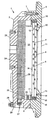
- the screen according to the invention shown in the drawing has a pressure-resistant in the sense of explosion protection housing 1, which is formed essentially of a base body 2, a frame 3 and a disc 4.
- the base body 2 has a frame 3 facing stop surface 5, against which a stop surface 6 of the frame 3.
- the gap lengths and gap widths between the abutment surfaces 5, 6 of the main body 2 and the frame 3 are designed so that they fully meet the requirements and requirements of Explosionsschtzes.
- the firm cohesion of the base body 2 and the frame 3 is ensured by the connection parts corresponding to the requirements, preferably screws 7.
- disc 4 is designed as a so-called composite disc and has to at least two parallel individual discs 8, 9.
- the disc 4 is fixed to the frame 3, wherein an edge region 10 of the outer side 11 of the outer single disc 8 rests against a contact surface 12 of the frame 3.
- the existing between the edge region 10 and the contact surface 12 column meet with respect to their gap length and gap width also the requirements of the explosion protection regulations.
- a seal 13 is provided, which is expediently mounted in a formed in the frame 3 groove 14.
- Another sealing material 15 may be arranged on the frontal circumference of the disc 4, wherein the width of the sealing material 15 may be approximately equal to the total thickness of the disc 4.
- the determination of the disc 4 on the frame 3 may be appropriate over a preferred Angular pressure piece 16 carried by means not shown here screws.
- a leg 17 of the pressure member 16 which engage over the outer side 11 opposite rear side 18 of the disc 4 and another leg 19 of the pressure member 16 may include the sealing material 15 at the front periphery of the disc 4.
- the frame 3 and the disc 4 space 20 of the pressure-resistant housing 1 is an LCD display 21 which is adjacent to the rear side 18 of the inner single disc 9.
- the LCD display 21 may be held by compression springs 22 which preferably engage the circumference of the LCD display 21 and are supported on the base body 2.
- an explosion pressure damping material 25 located in the space 20 between a rear wall 23 of the base body 2 and the back 24 of the LCD display 21, an explosion pressure damping material 25, which may be designed as approximately flat rectangular shaped body and adjacent to the rear wall 23.
- the volume of the explosion pressure damping material 25 may be about 30 to 60%, preferably about 45% of the void volume of the space 20.
- the explosion pressure damping material 25 has a relatively low specific gravity and has a plurality of small cross-section, not closed, but continuous channels in the form of pores and / or gaps. These small through pores and gaps serve to accommodate an explosive mixture possibly occurring in the pressure-resistant housing 1 and their inside diameter is dimensioned such that it is smaller than the respective boundary gap width of the explosion mixture.
- a flame trap 27 may be provided and also the base body 2 may have a PA terminal 28.
- the incombustible blast pressure damping material 25 may be metal, ceramic, slag wool, glass, glass wool or the like.
- the screen according to the invention with the explosion pressure damping material 25 can be designed so that the flameproof housing 1, despite a very lightweight design withstand four times the value of the reference pressure, so that a single piece test is not required in terms of compressive strength.
Landscapes
- Physics & Mathematics (AREA)
- Nonlinear Science (AREA)
- Optics & Photonics (AREA)
- Crystallography & Structural Chemistry (AREA)
- Chemical & Material Sciences (AREA)
- General Physics & Mathematics (AREA)
- Mathematical Physics (AREA)
- Casings For Electric Apparatus (AREA)
- Devices For Indicating Variable Information By Combining Individual Elements (AREA)
- Color Image Communication Systems (AREA)
- Control Of Throttle Valves Provided In The Intake System Or In The Exhaust System (AREA)
- Liquid Crystal (AREA)
- Polymerisation Methods In General (AREA)
Description
- Die Erfindung betrifft einen Bildschirm mit den Merkmalen des Oberbegriffs des Anspruchs 1.
- Die Aufgabe der Erfindung besteht darin, einen Bildschirm mit den Merkmalen des Oberbegriffs des Anspruchs 1 dahingehend weiterzubilden, daß eine Verwendung in explosionsgefährdeter Umgebung mit einfachen Mitteln, niedrigem Gewicht und großer Sichtfläche erzielt wird.
- Diese Aufgabe wird erfindungsgemäß durch die Merkmale des Anspruchs 1 gelöst.
- Zweckmäßige Ausgestaltungen und Weiterbildungen der Erfindung sind durch die Merkmale der Unteransprüche gekennzeichnet.
- Weitere Vorteile und wesentliche Einzelheiten der Erfindung sind der nachfolgenden Beschreibung und der Zeichnung zu entnehmen, die in einer einzigen Figur in schematischer Darstellung eine bevorzugte Ausführungsform als Beispiel zeigt.
- Aus dem Stand der Technik ist bereits eine in einem explosionsfesten Gehäuse eingeschlossene LCD-Anzeige bekannt (US 5 422 494 A).
- Der in der Zeichnung dargestellte erfindungsgemäße Bildschirm weist ein im Sinne des Explosionsschutzes druckfestes Gehäuse 1 auf, das im wesentlichen aus einem Grundkörper 2, einem Rahmen 3 und einer Scheibe 4 gebildet ist. Der Grundkörper 2 besitzt eine dem Rahmen 3 zugewandte Anschlagfläche 5, an der eine Anschlagfläche 6 des Rahmens 3 anliegt. Die Spaltlängen und Spaltweiten zwischen den Anschlagflächen 5, 6 des Grundkörpers 2 und des Rahmens 3 sind so ausgeführt, daß sie den Vorschriften und Anforderungen des Explosionsschtzes in vollem Umfang genügen. Der feste Zusammenhalt des Grundkörpers 2 und des Rahmens 3 wird durch den Anforderungen entsprechende Verbindungsteile, bevorzugt Schrauben 7, gewährleistet.
- Die den Anforderungen des Explosionsschutzes ebenfalls genügende Scheibe 4 ist als sogenannte Verbundscheibe ausgeführt und weist dazu mindestens zwei parallele Einzelscheiben 8, 9 auf. Die Scheibe 4 ist an dem Rahmen 3 befestigt, wobei ein Randbereich 10 der Außenseite 11 der äußeren Einzelscheibe 8 an einer Anlagefläche 12 des Rahmens 3 anliegt. Die zwischen dem Randbereich 10 und der Anlagefläche 12 bestehenden Spalte erfüllen hinsichtlich ihrer Spaltlänge und Spaltweite ebenfalls die Forderungen der Explosionsschutzvorschriften.
- Außerdem ist zu erkennen, daß zwischen dem außenseitigen Randbereich 10 der Einzelscheibe 8 und dem Rahmen 3 eine Dichtung 13 vorgesehen ist, die zweckmäßig in einer in dem Rahmen 3 ausgebildeten Nut 14 gelagert ist. Ein weiteres Dichtungsmaterial 15 kann am stirnseitigen Umfang der Scheibe 4 angeordnet sein, wobei die Breite des Dichtungsmaterials 15 etwa gleich der Gesamtdicke der Scheibe 4 sein kann. Die Festlegung der Scheibe 4 an dem Rahmen 3 kann zweckmäßig über ein bevorzugt winkelförmiges Druckstück 16 mittels hier nicht dargestellten Halteschrauben erfolgen. Dabei kann ein Schenkel 17 des Druckstücks 16 die der Außenseite 11 gegenüberliegende Hinterseite 18 der Scheibe 4 übergreifen und ein weiterer Schenkel 19 des Druckstücks 16 kann das Dichtungsmaterial 15 am stirnseitigen Umfang der Scheibe 4 umfassen.
- In dem von dem Grundkörper 2, dem Rahmen 3 und der Scheibe 4 begrenzten Raum 20 des druckfesten Gehäuses 1 befindet sich ein LCD-Display 21, das an die Hinterseite 18 der inneren Einzelscheibe 9 angrenzt. Das LCD-Display 21 kann über Druckfedern 22 gehalten sein, die bevorzugt am Umfang des LCD-Displays 21 angreifen und am Grundkörper 2 abgestützt sind.
- Schließlich befindet sich in dem Raum 20 zwischen einer Rückwand 23 des Grundkörpers 2 und der Rückseite 24 des LCD-Displays 21 ein Explosionsdruckdämpfungsmaterial 25, das als in etwa flachrechteckförmiger Körper ausgeführt sein kann und an die Rückwand 23 angrenzt. Das Volumen des Explosionsdruckdämpfungsmaterials 25 kann etwa 30 bis 60 %, vorzugsweise ungefähr 45 % des Leervolumens des Raumes 20 betragen. Das Explosionsdruckdämpfungsmaterial 25 hat ein relativ geringes spezifisches Gewicht und weist eine Vielzahl querschnittskleiner, nicht geschlossener, sondern durchgehender Kanäle in Form von Poren und/oder Spalte auf. Diese kleinen durchgehenden Poren und Spalte dienen der Aufnahme eines eventuell im druckfesten Gehäuse 1 auftretenden Explosivgemisches und ihre lichte Weite ist so bemessen, daß sie kleiner ist als die jeweilige Grenzspaltweite des Explosionsgemisches.
- An einer Seitenwand 26 des Grundkörpers 2 kann zudem eine Flammsperre 27 vorgesehen sein und außerdem kann der Grundkörper 2 einen PA-Anschluß 28 aufweisen.
- Im Falle einer in dem Bildschirmgehäuse auftretenden Explosion wird das explosible Gemisch in der der Explosion vorangehenden Druckwelle hoch verdichtet. Dieses hoch verdichtete Explosivgemisch gelangt dabei zwangsläufig in die feinen Kanäle des Explosionsdruckdämpfungsmaterials 25, wo es auf Grund des kleinen Volumens der einzelnen Kanäle, Poren und Spalte mit einem ausgesprochen niedrigen zeitlichen Druckanstieg verbrennt oder gar unverbrannt bleibt. Das führt im Gesamtvolumen des Gehäuses 1 ebenfalls zu einem geringen zeitlichen Druckanstieg und letztlich zu einem sehr niedrigen Explosionsdruck, wobei der tatsächlich auftretende Bezugsdruck bis auf nur etwa 10 % desjenigen Bezugsdrucks gedämpft wird, der sonst in dem leeren Bildschirmgehäuse auftreten würde. Auf Grund dieser Maßnahmen kann das gesamte Bildschirmgehäuse deutlich dünnwandiger und somit wesentlich leichter ausgeführt werden. Das unbrennbare Explosionsdruckdämpfungsmaterial 25 kann aus Metall, Keramik, Schlackenwolle, Glas, Glaswolle oder dergleichen bestehen. Zweckmäßig kann der erfindungsgemäße Bildschirm mit dem Explosionsdruckdämpfungsmaterial 25 so ausgelegt werden, daß das druckfeste Gehäuse 1 trotz einer sehr leichtgewichtigen Ausführung dem vierfachen Wert des Bezugsdrucks standhält, so daß eine Einzelstückprüfung hinsichtlich der Druckfestigkeit nicht erforderlich ist.
Claims (16)
- Bildschirm für ein EDV-System, mit einem eine durchsichtige Scheibe (4) aufweisenden Gehäuse (1), dadurch gekennzeichnet, daß in einem Raum (20) des Gehäuses (1) ein LCD-Display (21) und ein unbrennbares Explosionsdruckdämpfungsmaterial (25) angeordnet ist und daß das Gehäuse mit der Scheibe (4) als im Sinne des Explosionsschutzes druckfestes Gehäuse (1) ausgebildet ist.
- Bildschirm nach vorstehendem Anspruch, dadurch gekennzeichnet, daß das Explosionsdruckdämpfungsmaterial (25) in dem Raum (20) des druckfesten Gehäuses (1) an der der Scheibe (4) gegenüberliegenden Rückseite (24) des LCD-Displays (21) angeordnet ist.
- Bildschirm nach einem oder mehreren der vorstehenden Ansprüche, dadurch gekennzeichnet, daß das Explosionsdruckdämpfungsmaterial (25) durchgehende Poren und/oder Spalte für die Aufnahme eines Explosionsgemisches aufweist.
- Bildschirm nach einem oder mehreren der vorstehenden Ansprüche, dadurch gekennzeichnet, daß die lichte Weite der Poren und Spalte in dem Explosionsdruckdämpfungsmaterial (25) kleiner ist als die jeweilige Grenzspaltweite für das Explosionsgemisch.
- Bildschirm nach einem oder mehreren der vorstehenden Ansprüche, dadurch gekennzeichnet, daß das Volumen des Explosionsdruckdämpfungsmaterials (25) etwa 30 bis 60 Prozent, vorzugsweise etwa 45 Prozent des Leervolumens des Raumes (20) im druckfesten Gehäuse (1) ist.
- Bildschirm nach einem oder mehreren der vorstehenden Ansprüche, dadurch gekennzeichnet, daß das druckfeste Gehäuse (1) einen Grundkörper (2) und einen Rahmen (3) aufweist, die mittels bevorzugt schraubbaren Verbindungsteilen (7) an aneinanderliegenden Anschlagflächen (5, 6) zusammengefügt sind.
- Bildschirm nach einem oder mehreren der vorstehenden Ansprüche, dadurch gekennzeichnet, daß die Scheibe (4) eine aus mindestens zwei parallelen Einzelscheiben (8, 9) gebildete Verbundscheibe ist.
- Bildschirm nach einem oder mehreren der vorstehenden Ansprüche, dadurch gekennzeichnet, daß ein Randbereich (10) der dem LCD-Display (21) abgewandten Außenseite (11) der Scheibe (4) an einer Anlagefläche (12) des Rahmens (3) anliegt.
- Bildschirm nach einem oder mehreren der vorstehenden Ansprüche, dadurch gekennzeichnet, daß die Spaltlängen und -weiten zwischen den aneinanderliegenden Anschlagflächen (5, 6) des Grundkörpers (2) und des Rahmens (3) sowie der Scheibenaußenseite (11) und der Anlagefläche (12) des Rahmens (3) gemäß den Ex-Vorschriften ausgeführt sind.
- Bildschirm nach einem oder mehreren der vorstehenden Ansprüche, dadurch gekennzeichnet, daß zwischen dem Rahmen (3) des druckfesten Gehäuses (1) und der Außenseite (11) der Scheibe (4) eine Dichtung (13) angeordnet ist.
- Bildschirm nach einem oder mehreren der vorstehenden Ansprüche, dadurch gekennzeichnet, daß die Dichtung (13) in einer Nut (14) des Gehäuserahmens (3) gelagert ist.
- Bildschirm nach einem oder mehreren der vorstehenden Ansprüche, dadurch gekennzeichnet, daß die Scheibe (4) an dem Rahmen (3) des druckfesten Gehäuses (1) über ein Druckstück (16) festgelegt ist, das die der Außenseite (11) gegenüberliegende Hinterseite (18) der Scheibe (4) übergreift.
- Bildschirm nach einem oder mehreren der vorstehenden Ansprüche, dadurch gekennzeichnet, daß am stirnseitigen Umfang der Scheibe (4) ein Dichtungsmaterial (15) vorgesehen ist, das mindestens teilweise von einem Schenkel (19) des Druckstücks (16) übergriffen ist.
- Bildschirm nach einem oder mehreren der vorstehenden Ansprüche, dadurch gekennzeichnet, daß das LCD-Display (21) über eine oder mehrere Federn (22) am Grundkörper (2) des druckfesten Gehäuses (1) abgestützt ist.
- Bildschirm nach einem oder mehreren der vorstehenden Ansprüche, dadurch gekennzeichnet, daß das Explosionsdruckdämpfungsmaterial (25) an eine Rückwand (23) des Gehäusegrundkörpers (2) angrenzt.
- Bildschirm nach einem oder mehreren der vorstehenden Ansprüche, dadurch gekennzeichnet, daß dem Grundkörper (2) des druckfesten Gehäuses (1) eine Flammsperre (27) zugeordnet ist.
Applications Claiming Priority (2)
| Application Number | Priority Date | Filing Date | Title |
|---|---|---|---|
| DE19860383A DE19860383B4 (de) | 1998-12-28 | 1998-12-28 | Bildschirm |
| DE19860383 | 1998-12-28 |
Publications (3)
| Publication Number | Publication Date |
|---|---|
| EP1016892A2 EP1016892A2 (de) | 2000-07-05 |
| EP1016892A3 EP1016892A3 (de) | 2001-09-26 |
| EP1016892B1 true EP1016892B1 (de) | 2007-04-25 |
Family
ID=7892884
Family Applications (1)
| Application Number | Title | Priority Date | Filing Date |
|---|---|---|---|
| EP99126014A Expired - Lifetime EP1016892B1 (de) | 1998-12-28 | 1999-12-27 | Bildschirm |
Country Status (3)
| Country | Link |
|---|---|
| EP (1) | EP1016892B1 (de) |
| AT (1) | ATE360835T1 (de) |
| DE (2) | DE19860383B4 (de) |
Cited By (1)
| Publication number | Priority date | Publication date | Assignee | Title |
|---|---|---|---|---|
| CN106486900A (zh) * | 2016-11-01 | 2017-03-08 | 中科电力装备(安徽)智能化科技有限公司 | 一种继电保护器柜 |
Families Citing this family (10)
| Publication number | Priority date | Publication date | Assignee | Title |
|---|---|---|---|---|
| DE202009017392U1 (de) | 2009-12-22 | 2010-03-11 | Bartec Gmbh | Elektrotechnisches Gerät |
| DE102009059946B4 (de) | 2009-12-22 | 2014-08-28 | Bartec Gmbh | Elektrotechnisches Gerät |
| BR112015004369B1 (pt) | 2012-08-28 | 2020-12-01 | Micro Motion, Inc. | alojamento resistente ao fogo, e, método de formar o mesmo |
| DE102014206433B3 (de) * | 2014-04-03 | 2015-08-20 | Ecom Instruments Gmbh | Geräte-Anordnung, insbesondere zur Verwendung in einem explosionsgefährdeten Bereich |
| DE102014206436B3 (de) * | 2014-04-03 | 2015-08-20 | Ecom Instruments Gmbh | Geräte-Anordnung, insbesondere zur Verwendung in einem explosionsgefährdeten Bereich |
| DE202015005015U1 (de) * | 2015-07-17 | 2016-10-18 | Auma Riester Gmbh & Co. Kg | Explosionsgeschütztes Gehäuse |
| DE102017112159A1 (de) | 2017-06-01 | 2018-12-06 | R. Stahl Schaltgeräte GmbH | Explosionssicheres Gehäuse mit innerer Druckentlastung |
| DE102017112153A1 (de) | 2017-06-01 | 2018-12-06 | R. Stahl Schaltgeräte GmbH | Explosionssicheres Gehäuse mit innerer Druckentlastung |
| DE102017112150B4 (de) | 2017-06-01 | 2019-02-07 | R.Stahl Schaltgeräte GmbH | Explosionssicheres Gehäuse mit innerer Druckreduzierung |
| DE102018118195B4 (de) * | 2018-07-27 | 2020-06-04 | R. Stahl Schaltgeräte GmbH | Explosionssicheres Gehäuse mit geteiltem Deckel |
Family Cites Families (5)
| Publication number | Priority date | Publication date | Assignee | Title |
|---|---|---|---|---|
| DE2624562A1 (de) * | 1976-06-01 | 1977-12-15 | G Makeevskij Nii Bezopasnosti | Material zur herstellung von explosionsschutzhuellen, dessen verwendung und deren herstellung |
| US5173374A (en) * | 1991-03-12 | 1992-12-22 | Globe-Union, Inc. | Explosion attenuation system and method for assembly in battery |
| DE4232961A1 (de) * | 1992-10-01 | 1994-04-07 | Vb Autobatterie Gmbh | Mehrzelliger Bleiakkumulator |
| US5422494A (en) * | 1992-10-16 | 1995-06-06 | The Scott Fetzer Company | Barrier transmission apparatus |
| GB2297431A (en) * | 1995-01-27 | 1996-07-31 | Asep Bv | Explosion-proof computing apparatus |
-
1998
- 1998-12-28 DE DE19860383A patent/DE19860383B4/de not_active Expired - Fee Related
-
1999
- 1999-12-27 AT AT99126014T patent/ATE360835T1/de not_active IP Right Cessation
- 1999-12-27 DE DE59914311T patent/DE59914311D1/de not_active Expired - Lifetime
- 1999-12-27 EP EP99126014A patent/EP1016892B1/de not_active Expired - Lifetime
Non-Patent Citations (1)
| Title |
|---|
| None * |
Cited By (1)
| Publication number | Priority date | Publication date | Assignee | Title |
|---|---|---|---|---|
| CN106486900A (zh) * | 2016-11-01 | 2017-03-08 | 中科电力装备(安徽)智能化科技有限公司 | 一种继电保护器柜 |
Also Published As
| Publication number | Publication date |
|---|---|
| EP1016892A2 (de) | 2000-07-05 |
| DE59914311D1 (de) | 2007-06-06 |
| ATE360835T1 (de) | 2007-05-15 |
| DE19860383B4 (de) | 2005-06-09 |
| EP1016892A3 (de) | 2001-09-26 |
| DE19860383A1 (de) | 2000-07-06 |
Similar Documents
| Publication | Publication Date | Title |
|---|---|---|
| EP3631924B1 (de) | Explosionssicheres gehäuse mit druckentlastung | |
| DE19860383B4 (de) | Bildschirm | |
| DE102017112150B4 (de) | Explosionssicheres Gehäuse mit innerer Druckreduzierung | |
| DE2250549A1 (de) | Mehrfachscheibe mit zwei glasscheiben und mindestens einer schlagfesten zwischenscheibe | |
| EP3199207A2 (de) | Druckentlastungsvorrichtung, modulare druckentlastungseinheit und brandschutzvorrichtung | |
| DE102014206433B3 (de) | Geräte-Anordnung, insbesondere zur Verwendung in einem explosionsgefährdeten Bereich | |
| DE29823088U1 (de) | Bildschirm | |
| DE202016000506U1 (de) | Druckentlastungsvorrichtung | |
| DE3311252C2 (de) | ||
| DE3723219A1 (de) | Fensterverglasung fuer abgeschirmte raeume | |
| EP0053774B1 (de) | Sprengwirkungshemmende Verglasung aus Verbundglas | |
| EP0328952A1 (de) | Elektromagnetisch abgeschirmtes und thermisch isoliertes Fenster aus einem Glasverbundelement mit Halterungsträger | |
| DE3042347A1 (de) | Laermarme brenn- und plasamaschneideinrichtung | |
| DE102010034888A1 (de) | Druckfest gekapseltes Gehäuse | |
| EP0002494B1 (de) | Brandschutzverkleidung für Stahlkonstruktionsteile wie Stahlträger, Stahlstützen oder dgl. | |
| DE102014206436B3 (de) | Geräte-Anordnung, insbesondere zur Verwendung in einem explosionsgefährdeten Bereich | |
| DE3227500A1 (de) | Transportabler einbaukanal mit feuerschutz-klassifikation | |
| AT164921B (de) | Feuersicherer Schrank für Akten u. dgl. | |
| DE202006016403U1 (de) | Tür, insbesondere Feuer- und Brandschutztür | |
| DE102020132983B3 (de) | Mobile Laserschutzwand | |
| DE102019105597A1 (de) | Mobile Schutzwand | |
| DE102011052106B3 (de) | Aufnahmeelement für Türbänder | |
| DE2758292C2 (de) | Tiefofen mit aufsetzbarem Deckel | |
| DE19511040C2 (de) | Ofenverkleidung | |
| DE2234911C3 (de) | Als rohrförmiger Ansaugschalldämpfer ausgebildete Haube für Gas- oder ölbrenner |
Legal Events
| Date | Code | Title | Description |
|---|---|---|---|
| PUAI | Public reference made under article 153(3) epc to a published international application that has entered the european phase |
Free format text: ORIGINAL CODE: 0009012 |
|
| 17P | Request for examination filed |
Effective date: 19991227 |
|
| AK | Designated contracting states |
Kind code of ref document: A2 Designated state(s): AT BE CH CY DE DK ES FI FR GB GR IE IT LI LU MC NL PT SE Kind code of ref document: A2 Designated state(s): AT CY DE FR GB IT |
|
| AX | Request for extension of the european patent |
Free format text: AL;LT;LV;MK;RO;SI |
|
| PUAL | Search report despatched |
Free format text: ORIGINAL CODE: 0009013 |
|
| AK | Designated contracting states |
Kind code of ref document: A3 Designated state(s): AT BE CH CY DE DK ES FI FR GB GR IE IT LI LU MC NL PT SE |
|
| AX | Request for extension of the european patent |
Free format text: AL;LT;LV;MK;RO;SI |
|
| RIC1 | Information provided on ipc code assigned before grant |
Free format text: 7G 02F 1/13 A, 7H 05K 5/06 B, 7H 02B 1/28 B |
|
| AKX | Designation fees paid |
Free format text: AT CY DE FR GB IT |
|
| GRAP | Despatch of communication of intention to grant a patent |
Free format text: ORIGINAL CODE: EPIDOSNIGR1 |
|
| GRAS | Grant fee paid |
Free format text: ORIGINAL CODE: EPIDOSNIGR3 |
|
| GRAA | (expected) grant |
Free format text: ORIGINAL CODE: 0009210 |
|
| AK | Designated contracting states |
Kind code of ref document: B1 Designated state(s): AT CY DE FR GB IT |
|
| REG | Reference to a national code |
Ref country code: GB Ref legal event code: FG4D Free format text: NOT ENGLISH |
|
| REF | Corresponds to: |
Ref document number: 59914311 Country of ref document: DE Date of ref document: 20070606 Kind code of ref document: P |
|
| GBT | Gb: translation of ep patent filed (gb section 77(6)(a)/1977) |
Effective date: 20070523 |
|
| ET | Fr: translation filed | ||
| PLBE | No opposition filed within time limit |
Free format text: ORIGINAL CODE: 0009261 |
|
| STAA | Information on the status of an ep patent application or granted ep patent |
Free format text: STATUS: NO OPPOSITION FILED WITHIN TIME LIMIT |
|
| 26N | No opposition filed |
Effective date: 20080128 |
|
| PGFP | Annual fee paid to national office [announced via postgrant information from national office to epo] |
Ref country code: AT Payment date: 20081204 Year of fee payment: 10 |
|
| PGFP | Annual fee paid to national office [announced via postgrant information from national office to epo] |
Ref country code: IT Payment date: 20081224 Year of fee payment: 10 |
|
| PGFP | Annual fee paid to national office [announced via postgrant information from national office to epo] |
Ref country code: GB Payment date: 20081002 Year of fee payment: 10 |
|
| PG25 | Lapsed in a contracting state [announced via postgrant information from national office to epo] |
Ref country code: CY Free format text: LAPSE BECAUSE OF FAILURE TO SUBMIT A TRANSLATION OF THE DESCRIPTION OR TO PAY THE FEE WITHIN THE PRESCRIBED TIME-LIMIT Effective date: 20070425 |
|
| PGFP | Annual fee paid to national office [announced via postgrant information from national office to epo] |
Ref country code: FR Payment date: 20081229 Year of fee payment: 10 |
|
| PGFP | Annual fee paid to national office [announced via postgrant information from national office to epo] |
Ref country code: DE Payment date: 20091222 Year of fee payment: 11 |
|
| GBPC | Gb: european patent ceased through non-payment of renewal fee |
Effective date: 20091227 |
|
| PG25 | Lapsed in a contracting state [announced via postgrant information from national office to epo] |
Ref country code: AT Free format text: LAPSE BECAUSE OF NON-PAYMENT OF DUE FEES Effective date: 20091227 |
|
| REG | Reference to a national code |
Ref country code: FR Ref legal event code: ST Effective date: 20100831 |
|
| PG25 | Lapsed in a contracting state [announced via postgrant information from national office to epo] |
Ref country code: FR Free format text: LAPSE BECAUSE OF NON-PAYMENT OF DUE FEES Effective date: 20091231 |
|
| PG25 | Lapsed in a contracting state [announced via postgrant information from national office to epo] |
Ref country code: GB Free format text: LAPSE BECAUSE OF NON-PAYMENT OF DUE FEES Effective date: 20091227 |
|
| PG25 | Lapsed in a contracting state [announced via postgrant information from national office to epo] |
Ref country code: IT Free format text: LAPSE BECAUSE OF NON-PAYMENT OF DUE FEES Effective date: 20091227 |
|
| REG | Reference to a national code |
Ref country code: DE Ref legal event code: R119 Ref document number: 59914311 Country of ref document: DE Effective date: 20110701 |
|
| PG25 | Lapsed in a contracting state [announced via postgrant information from national office to epo] |
Ref country code: DE Free format text: LAPSE BECAUSE OF NON-PAYMENT OF DUE FEES Effective date: 20110701 |