EP1015744B1 - Kolbenzuordnung mit variabler kompression - Google Patents
Kolbenzuordnung mit variabler kompression Download PDFInfo
- Publication number
- EP1015744B1 EP1015744B1 EP98948218A EP98948218A EP1015744B1 EP 1015744 B1 EP1015744 B1 EP 1015744B1 EP 98948218 A EP98948218 A EP 98948218A EP 98948218 A EP98948218 A EP 98948218A EP 1015744 B1 EP1015744 B1 EP 1015744B1
- Authority
- EP
- European Patent Office
- Prior art keywords
- pistons
- piston
- arm
- axis
- assembly
- Prior art date
- Legal status (The legal status is an assumption and is not a legal conclusion. Google has not performed a legal analysis and makes no representation as to the accuracy of the status listed.)
- Expired - Lifetime
Links
Images


Classifications
-
- F—MECHANICAL ENGINEERING; LIGHTING; HEATING; WEAPONS; BLASTING
- F02—COMBUSTION ENGINES; HOT-GAS OR COMBUSTION-PRODUCT ENGINE PLANTS
- F02B—INTERNAL-COMBUSTION PISTON ENGINES; COMBUSTION ENGINES IN GENERAL
- F02B75/00—Other engines
- F02B75/04—Engines with variable distances between pistons at top dead-centre positions and cylinder heads
-
- F—MECHANICAL ENGINEERING; LIGHTING; HEATING; WEAPONS; BLASTING
- F02—COMBUSTION ENGINES; HOT-GAS OR COMBUSTION-PRODUCT ENGINE PLANTS
- F02B—INTERNAL-COMBUSTION PISTON ENGINES; COMBUSTION ENGINES IN GENERAL
- F02B75/00—Other engines
- F02B75/26—Engines with cylinder axes coaxial with, or parallel or inclined to, main-shaft axis; Engines with cylinder axes arranged substantially tangentially to a circle centred on main-shaft axis
-
- F—MECHANICAL ENGINEERING; LIGHTING; HEATING; WEAPONS; BLASTING
- F02—COMBUSTION ENGINES; HOT-GAS OR COMBUSTION-PRODUCT ENGINE PLANTS
- F02B—INTERNAL-COMBUSTION PISTON ENGINES; COMBUSTION ENGINES IN GENERAL
- F02B75/00—Other engines
- F02B75/02—Engines characterised by their cycles, e.g. six-stroke
- F02B2075/022—Engines characterised by their cycles, e.g. six-stroke having less than six strokes per cycle
- F02B2075/025—Engines characterised by their cycles, e.g. six-stroke having less than six strokes per cycle two
Definitions
- U.S. Patent 4,011,842 defines a four cylinder piston engine that utilizes two double ended pistons connected to a T-shaped T-shaped connecting member that causes a crankshaft to rotate.
- the T-shaped connecting member is attached at each of the T-cross arm to a double ended piston.
- a centrally located point on the T-cross arm is rotatably attached to a fixed point, and the bottom of the T is rotatably attached to a crank pin which is connected to the crankshaft by a crankthrow which includes a counter weight.
- the assembly includes at least two joints, each joint coupling one of the drive arms to one of the pistons and providing four degrees of freedom between the drive arm and the piston, the four degrees of freedom being a first degree of freedom that includes rotation about the drive arm axis, a second degree of freedom that includes sliding along the drive arm axis, a third degree of freedom that includes pivoting about an axis perpendicular to the drive arm axis, and a fourth degree of freedom that includes sliding in the direction of the perpendicular axis, wherein each joint comprises an outer member coupled to the piston and an inner cylindrical member mounted within the outer member such that the inner cylindrical member slides along the perpendicular axis to provide the fourth degree of freedom.
- the pistons may be double ended pistons.
- the transition arm is coupled to each of the double ended pistons at approximately a centre of each piston.
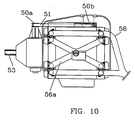
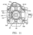
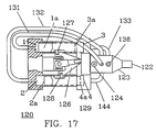
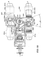
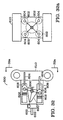
- FIG. 10 is a side view of engine 30 showing the exhaust manifold 56, intake manifold 56a and carburetor 56c. Pulleys 50a and 50b with timing belt 51 are also shown.
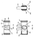
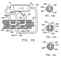
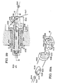
- FIG. 16 shows piston arm 116 in sleeve bearing 117.
- Sleeve bearing 117 is in pivot pin 115.
- Piston arm 116 can freely rotate in sleeve bearing 117 and the assembly of piston arm 116, Sleeve bearing 117 and pivot pin 115 and sleeve bearings 118a and 118b rotate in piston 110, and piston arm 116 can moved axially with the axis of sleeve bearing 117 to allow for the linear motion of double ended piston 110, and the motion of a transition arm to which piston arm 116 is attached.
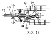
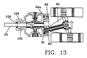
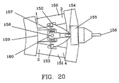
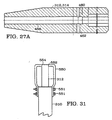
- barrel 414 Because outer barrel 420 is fixed, the rotation of barrel 414 causes barrel 414 to move linearly along axis, A, arrow 403. Barrel 414 is positioned between a collar 422 and a gear 424, both fixed to a main drive shaft 408. Drive shaft 408 is in turn fixed to flywheel 322. Thus, movement of barrel 414 along axis, A, is translated to linear movement of flywheel 322 along axis, A. This results in flywheel 322 sliding along axis, H, of drive arm 320 of transition arm 310, changing angle, ⁇ , and thus the stroke of the pistons. Thrust bearings 430 are located at both ends of barrel 414, and a sleeve bearing 432 is located between barrel 414 and shaft 408.
Landscapes
- Engineering & Computer Science (AREA)
- Chemical & Material Sciences (AREA)
- Combustion & Propulsion (AREA)
- Mechanical Engineering (AREA)
- General Engineering & Computer Science (AREA)
- Output Control And Ontrol Of Special Type Engine (AREA)
- Transmission Devices (AREA)
- Compressors, Vaccum Pumps And Other Relevant Systems (AREA)
- Valve Device For Special Equipments (AREA)
- Pistons, Piston Rings, And Cylinders (AREA)
Claims (11)
- Kolbenbaugruppe, umfassend:mindestens zwei Kolben (306, 308), die Achsen aufweisen, die auf einer gemeinsamen Ebene liegen und für eine Linearbewegung konfiguriert sind;einen Übergangsarm (310), der an jeden der Kolben gekoppelt ist und mindestens zwei Antriebsarme (312, 314) umfasst, wobei jeder Antriebsarm eine Antriebsarmachse definiert und der Übergangsarm ein Ende aufweist, das in ein Schwungrad (322) auf einer Welle (400) montiert ist, um sich in einem Kreis zu bewegen, damit die Linearbewegung der Kolben (306, 308) in die Drehbewegung der Welle übertragen wird; undein Universalgelenk (318), das den Übergangsarm mithilfe von zwei Bolzen mit einem Stützlager verbindet, um die Schwenkbewegung um zwei Achsen zu gestatten, wobei ein Zentrum des Universalgelenks nicht auf der gemeinsamen Ebene, sondern woanders liegt;dadurch gekennzeichnet, dass
die Baugruppe mindestens zwei Gelenke (334, 334a) umfasst, wobei jedes Gelenk einen der Antriebsarme an einen der Kolben (306, 308) koppelt und vier Freiheitsgrade zwischen dem Antriebsarm und dem Kolben bereitstellt, wobei sich die vier Freiheitsgrade zusammensetzen aus einem ersten Freiheitsgrad, der die Drehung um die Antriebsarmachse (307) umfasst, einem zweiten Freiheitsgrad, der das Verschieben längs der Antriebsarmachse (307) umfasst, einem dritten Freiheitsgrad, der das Schwenken um eine Achse (350) senkrecht zur Antriebsarmachse umfasst, und einem vierten Freiheitsgrad, der das Verschieben in Richtung der senkrechten Achse umfasst, wobei jedes Gelenk ein äußeres Element (338), das an den Kolben gekoppelt ist, und ein inneres zylindrisches Element (341) umfasst, das in das äußere Element so montiert ist, dass das innere zylindrische Element sich längs der senkrechten Achse verschiebt, um den vierten Freiheitsgrad bereitzustellen. - Kolbenbaugruppe nach Anspruch 1, bei der mindestens einer der Kolben einen doppelendigen Kolben (306, 308) umfasst.
- Kolbenbaugruppe nach Anspruch 2, bei der ein zweiter der mindestens zwei Kolben einen doppelendigen Kolben (306, 308) umfasst.
- Kolbenbaugruppe nach einem der vorhergehenden Ansprüche, bei der die Achse eines ersten der Kolben (306) und eine Drehachse eines drehbaren Elementes (322), das an den Übergangsarm (310) gekoppelt ist, auf einer ersten Ebene liegen und die Achse des zweiten der Kolben (308) und die Achse des drehbaren Elementes auf einer zweiten Ebene liegen, die zur ersten Ebene im Wesentlichen senkrecht ist.
- Kolbenbaugruppe nach einem der vorhergehenden Ansprüche, die vier Kolben (306, 308) umfasst.
- Baugruppe nach einem der vorhergehenden Ansprüche, bei der die zwei Bolzen (354, 356) ein Kreuzelement bilden.
- Baugruppe nach einem der vorhergehenden Ansprüche, die außerdem einen zweiten Übergangsarm umfasst, der in Bezug auf den an die Kolben gekoppelten Übergangsarm mit den Rückseiten aneinander montiert und gegenüber demselben um 180° phasenverschoben ist.
- Baugruppe nach Anspruch 7, bei der die Übergangsarme durch ein Rotationselement gekoppelt sind.
- Baugruppe nach Anspruch 7, bei der der zweite Übergangsarm an ein Element gekoppelt ist, das sich einen gemeinsamen Zylinder mit einem der Kolben teilt.
- Kolbenbaugruppe nach einem der vorhergehenden Ansprüche, bei der ein Verdichtungsverhältnis der Kolben so einstellbar ist, dass es bei konstant gehaltener Leistung und dem von 6:1 auf 12:1 erhöhten Verdichtungsverhältnis eine Verringerung des Kraftstoffverbrauchs von ungefähr 25 % gibt.
- Kolbenbaugruppe nach einem der vorhergehenden Ansprüche, bei der der Übergangsarm eine Vielzahl von Antriebsarmen umfasst, wobei jeder Antriebsarm durch ein Gelenk, das vier Freiheitsgrade aufweist, an einen jeweiligen der Kolben gekoppelt ist.
Applications Claiming Priority (3)
| Application Number | Priority Date | Filing Date | Title |
|---|---|---|---|
| US92904297A | 1997-09-15 | 1997-09-15 | |
| US929042 | 1997-09-15 | ||
| PCT/US1998/019164 WO1999014471A1 (en) | 1997-09-15 | 1998-09-15 | Variable compression piston assembly |
Publications (3)
| Publication Number | Publication Date |
|---|---|
| EP1015744A1 EP1015744A1 (de) | 2000-07-05 |
| EP1015744A4 EP1015744A4 (de) | 2004-03-03 |
| EP1015744B1 true EP1015744B1 (de) | 2008-05-28 |
Family
ID=25457228
Family Applications (1)
| Application Number | Title | Priority Date | Filing Date |
|---|---|---|---|
| EP98948218A Expired - Lifetime EP1015744B1 (de) | 1997-09-15 | 1998-09-15 | Kolbenzuordnung mit variabler kompression |
Country Status (9)
| Country | Link |
|---|---|
| EP (1) | EP1015744B1 (de) |
| JP (1) | JP4260363B2 (de) |
| KR (1) | KR100599138B1 (de) |
| CN (1) | CN1214180C (de) |
| AT (1) | ATE397149T1 (de) |
| CA (1) | CA2300111C (de) |
| DE (1) | DE69839565D1 (de) |
| RU (1) | RU2219358C2 (de) |
| WO (1) | WO1999014471A1 (de) |
Families Citing this family (9)
| Publication number | Priority date | Publication date | Assignee | Title |
|---|---|---|---|---|
| US6460450B1 (en) * | 1999-08-05 | 2002-10-08 | R. Sanderson Management, Inc. | Piston engine balancing |
| ATE362043T1 (de) * | 1999-08-05 | 2007-06-15 | Sanderson R Man Inc | Balancierung einer kolbenmaschine |
| JP2003510495A (ja) * | 1999-08-05 | 2003-03-18 | アール サンダーソン マネージメント インコーポレイテッド | ピストン組立体 |
| WO2002063139A1 (en) * | 2001-02-08 | 2002-08-15 | R. Sanderson Management, Inc. | Variable stroke/clearance mechanism |
| US6854377B2 (en) * | 2001-11-02 | 2005-02-15 | R. Sanderson Management, Inc. | Variable stroke balancing |
| US7438029B2 (en) | 2004-03-18 | 2008-10-21 | R. Sanderson Management, Inc. | Piston waveform shaping |
| EP1766187A1 (de) * | 2004-05-26 | 2007-03-28 | R. Sanderson Management, Inc. | Mechanismus zur variierung von hub und abstand |
| AU2013202222B2 (en) * | 2008-03-14 | 2015-07-09 | Torkildsen, Odd Bernhard MR | Combustion engine having mutually connected pistons |
| US8511265B2 (en) * | 2009-06-01 | 2013-08-20 | Steven Don Arnold | Variable stroke and compression ratio engine |
Citations (2)
| Publication number | Priority date | Publication date | Assignee | Title |
|---|---|---|---|---|
| US2940325A (en) * | 1957-02-15 | 1960-06-14 | Nakesch Michael | Internal combustion engine with swash plate drive |
| US5630351A (en) * | 1993-05-07 | 1997-05-20 | Whisper Tech Limited | Wobble yoke assembly |
Family Cites Families (8)
| Publication number | Priority date | Publication date | Assignee | Title |
|---|---|---|---|---|
| US1772977A (en) * | 1929-02-25 | 1930-08-12 | Italien American Motors Inc | Internal-combustion engine |
| FR1416219A (fr) * | 1964-11-27 | 1965-10-29 | Système de transformation du mouvement linéaire en circulaire, pour moteurs thermiques et compresseurs | |
| DE1451926A1 (de) * | 1965-05-07 | 1970-03-05 | Pattas Dr Ing Konstantin | Brennkraft-Kolbenmaschine mit selbsttaetiger,den jeweiligen Anforderungen des Betriebs angepasster Verstellung des Kolbenhubs bei gleichzeitiger Verstellung des Verdichtungsverhaeltnisses |
| US4011842A (en) | 1975-09-08 | 1977-03-15 | Francis William Davies | Piston machine |
| US4174684A (en) * | 1977-05-23 | 1979-11-20 | Hallmann Eckhard P | Variable stroke internal combustion engine |
| US5007385A (en) * | 1989-07-15 | 1991-04-16 | Hiromasa Kitaguchi | Crankless engine |
| GB2287766B (en) | 1994-03-18 | 1998-01-28 | Yoshiki Kogyo Kk | Apparatus for mutual conversion between circular motion and reciprocal motion |
| US5553582A (en) * | 1995-01-04 | 1996-09-10 | Speas; Danny E. | Nutating disc engine |
-
1998
- 1998-09-15 RU RU2000109597/06A patent/RU2219358C2/ru not_active IP Right Cessation
- 1998-09-15 WO PCT/US1998/019164 patent/WO1999014471A1/en active IP Right Grant
- 1998-09-15 CN CNB988090643A patent/CN1214180C/zh not_active Expired - Fee Related
- 1998-09-15 DE DE69839565T patent/DE69839565D1/de not_active Expired - Lifetime
- 1998-09-15 EP EP98948218A patent/EP1015744B1/de not_active Expired - Lifetime
- 1998-09-15 JP JP2000511989A patent/JP4260363B2/ja not_active Expired - Lifetime
- 1998-09-15 AT AT98948218T patent/ATE397149T1/de not_active IP Right Cessation
- 1998-09-15 CA CA002300111A patent/CA2300111C/en not_active Expired - Fee Related
- 1998-09-15 KR KR1020007002573A patent/KR100599138B1/ko not_active IP Right Cessation
Patent Citations (2)
| Publication number | Priority date | Publication date | Assignee | Title |
|---|---|---|---|---|
| US2940325A (en) * | 1957-02-15 | 1960-06-14 | Nakesch Michael | Internal combustion engine with swash plate drive |
| US5630351A (en) * | 1993-05-07 | 1997-05-20 | Whisper Tech Limited | Wobble yoke assembly |
Also Published As
| Publication number | Publication date |
|---|---|
| ATE397149T1 (de) | 2008-06-15 |
| KR20010023889A (ko) | 2001-03-26 |
| JP2001516837A (ja) | 2001-10-02 |
| CA2300111C (en) | 2009-05-26 |
| WO1999014471A1 (en) | 1999-03-25 |
| JP4260363B2 (ja) | 2009-04-30 |
| CN1214180C (zh) | 2005-08-10 |
| CN1336982A (zh) | 2002-02-20 |
| EP1015744A1 (de) | 2000-07-05 |
| DE69839565D1 (de) | 2008-07-10 |
| EP1015744A4 (de) | 2004-03-03 |
| KR100599138B1 (ko) | 2006-07-12 |
| CA2300111A1 (en) | 1999-03-25 |
| RU2219358C2 (ru) | 2003-12-20 |
Similar Documents
| Publication | Publication Date | Title |
|---|---|---|
| US6397794B1 (en) | Piston engine assembly | |
| US7334548B2 (en) | Piston joint | |
| AU780611B2 (en) | Piston engine balancing | |
| US7007589B1 (en) | Piston assembly | |
| US6854377B2 (en) | Variable stroke balancing | |
| EP1015744B1 (de) | Kolbenzuordnung mit variabler kompression | |
| EP1471230B1 (de) | Massenausgleich einer Kolbenmaschine | |
| EP1200734B1 (de) | Kolbenmaschinenzusammenbauten und zugehöriges verfahren | |
| EP1114242B1 (de) | Kolbenverbindung | |
| EP1200720B1 (de) | Balancierung einer kolbenmaschine | |
| MXPA00002537A (en) | Variable compression piston assembly |
Legal Events
| Date | Code | Title | Description |
|---|---|---|---|
| PUAI | Public reference made under article 153(3) epc to a published international application that has entered the european phase |
Free format text: ORIGINAL CODE: 0009012 |
|
| 17P | Request for examination filed |
Effective date: 20000314 |
|
| AK | Designated contracting states |
Kind code of ref document: A1 Designated state(s): AT BE CH CY DE DK ES FI FR GB GR IE IT LI LU MC NL PT SE |
|
| A4 | Supplementary search report drawn up and despatched |
Effective date: 20040120 |
|
| RIC1 | Information provided on ipc code assigned before grant |
Ipc: 7F 16H 23/08 B Ipc: 7F 16H 23/06 B Ipc: 7F 16F 15/26 B Ipc: 7F 04B 1/32 B Ipc: 7F 04B 1/22 B Ipc: 7F 04B 1/14 B Ipc: 7F 01B 3/10 B Ipc: 7F 01B 3/00 B Ipc: 7F 02B 75/26 B Ipc: 7F 02B 75/04 A |
|
| 17Q | First examination report despatched |
Effective date: 20050624 |
|
| 17Q | First examination report despatched |
Effective date: 20050624 |
|
| GRAP | Despatch of communication of intention to grant a patent |
Free format text: ORIGINAL CODE: EPIDOSNIGR1 |
|
| GRAS | Grant fee paid |
Free format text: ORIGINAL CODE: EPIDOSNIGR3 |
|
| GRAA | (expected) grant |
Free format text: ORIGINAL CODE: 0009210 |
|
| AK | Designated contracting states |
Kind code of ref document: B1 Designated state(s): AT BE CH CY DE DK ES FI FR GB GR IE IT LI LU MC NL PT SE |
|
| REG | Reference to a national code |
Ref country code: GB Ref legal event code: FG4D |
|
| REG | Reference to a national code |
Ref country code: CH Ref legal event code: EP |
|
| REF | Corresponds to: |
Ref document number: 69839565 Country of ref document: DE Date of ref document: 20080710 Kind code of ref document: P |
|
| REG | Reference to a national code |
Ref country code: IE Ref legal event code: FG4D |
|
| PG25 | Lapsed in a contracting state [announced via postgrant information from national office to epo] |
Ref country code: FI Free format text: LAPSE BECAUSE OF FAILURE TO SUBMIT A TRANSLATION OF THE DESCRIPTION OR TO PAY THE FEE WITHIN THE PRESCRIBED TIME-LIMIT Effective date: 20080528 Ref country code: ES Free format text: LAPSE BECAUSE OF FAILURE TO SUBMIT A TRANSLATION OF THE DESCRIPTION OR TO PAY THE FEE WITHIN THE PRESCRIBED TIME-LIMIT Effective date: 20080908 |
|
| PG25 | Lapsed in a contracting state [announced via postgrant information from national office to epo] |
Ref country code: NL Free format text: LAPSE BECAUSE OF FAILURE TO SUBMIT A TRANSLATION OF THE DESCRIPTION OR TO PAY THE FEE WITHIN THE PRESCRIBED TIME-LIMIT Effective date: 20080528 Ref country code: AT Free format text: LAPSE BECAUSE OF FAILURE TO SUBMIT A TRANSLATION OF THE DESCRIPTION OR TO PAY THE FEE WITHIN THE PRESCRIBED TIME-LIMIT Effective date: 20080528 |
|
| NLV1 | Nl: lapsed or annulled due to failure to fulfill the requirements of art. 29p and 29m of the patents act | ||
| PG25 | Lapsed in a contracting state [announced via postgrant information from national office to epo] |
Ref country code: SE Free format text: LAPSE BECAUSE OF FAILURE TO SUBMIT A TRANSLATION OF THE DESCRIPTION OR TO PAY THE FEE WITHIN THE PRESCRIBED TIME-LIMIT Effective date: 20080828 Ref country code: PT Free format text: LAPSE BECAUSE OF FAILURE TO SUBMIT A TRANSLATION OF THE DESCRIPTION OR TO PAY THE FEE WITHIN THE PRESCRIBED TIME-LIMIT Effective date: 20081028 Ref country code: DK Free format text: LAPSE BECAUSE OF FAILURE TO SUBMIT A TRANSLATION OF THE DESCRIPTION OR TO PAY THE FEE WITHIN THE PRESCRIBED TIME-LIMIT Effective date: 20080528 |
|
| PG25 | Lapsed in a contracting state [announced via postgrant information from national office to epo] |
Ref country code: BE Free format text: LAPSE BECAUSE OF FAILURE TO SUBMIT A TRANSLATION OF THE DESCRIPTION OR TO PAY THE FEE WITHIN THE PRESCRIBED TIME-LIMIT Effective date: 20080528 |
|
| PLBE | No opposition filed within time limit |
Free format text: ORIGINAL CODE: 0009261 |
|
| STAA | Information on the status of an ep patent application or granted ep patent |
Free format text: STATUS: NO OPPOSITION FILED WITHIN TIME LIMIT |
|
| PG25 | Lapsed in a contracting state [announced via postgrant information from national office to epo] |
Ref country code: MC Free format text: LAPSE BECAUSE OF NON-PAYMENT OF DUE FEES Effective date: 20080930 |
|
| REG | Reference to a national code |
Ref country code: CH Ref legal event code: PL |
|
| 26N | No opposition filed |
Effective date: 20090303 |
|
| REG | Reference to a national code |
Ref country code: IE Ref legal event code: MM4A |
|
| REG | Reference to a national code |
Ref country code: FR Ref legal event code: ST Effective date: 20090529 |
|
| PG25 | Lapsed in a contracting state [announced via postgrant information from national office to epo] |
Ref country code: IE Free format text: LAPSE BECAUSE OF NON-PAYMENT OF DUE FEES Effective date: 20080915 |
|
| PG25 | Lapsed in a contracting state [announced via postgrant information from national office to epo] |
Ref country code: IT Free format text: LAPSE BECAUSE OF FAILURE TO SUBMIT A TRANSLATION OF THE DESCRIPTION OR TO PAY THE FEE WITHIN THE PRESCRIBED TIME-LIMIT Effective date: 20080528 |
|
| PG25 | Lapsed in a contracting state [announced via postgrant information from national office to epo] |
Ref country code: LI Free format text: LAPSE BECAUSE OF NON-PAYMENT OF DUE FEES Effective date: 20080930 Ref country code: FR Free format text: LAPSE BECAUSE OF NON-PAYMENT OF DUE FEES Effective date: 20080930 Ref country code: CH Free format text: LAPSE BECAUSE OF NON-PAYMENT OF DUE FEES Effective date: 20080930 |
|
| PG25 | Lapsed in a contracting state [announced via postgrant information from national office to epo] |
Ref country code: LU Free format text: LAPSE BECAUSE OF NON-PAYMENT OF DUE FEES Effective date: 20080915 |
|
| PG25 | Lapsed in a contracting state [announced via postgrant information from national office to epo] |
Ref country code: CY Free format text: LAPSE BECAUSE OF FAILURE TO SUBMIT A TRANSLATION OF THE DESCRIPTION OR TO PAY THE FEE WITHIN THE PRESCRIBED TIME-LIMIT Effective date: 20080528 |
|
| PG25 | Lapsed in a contracting state [announced via postgrant information from national office to epo] |
Ref country code: GR Free format text: LAPSE BECAUSE OF FAILURE TO SUBMIT A TRANSLATION OF THE DESCRIPTION OR TO PAY THE FEE WITHIN THE PRESCRIBED TIME-LIMIT Effective date: 20080829 |
|
| PGFP | Annual fee paid to national office [announced via postgrant information from national office to epo] |
Ref country code: DE Payment date: 20130919 Year of fee payment: 16 |
|
| PGFP | Annual fee paid to national office [announced via postgrant information from national office to epo] |
Ref country code: GB Payment date: 20130919 Year of fee payment: 16 |
|
| REG | Reference to a national code |
Ref country code: DE Ref legal event code: R119 Ref document number: 69839565 Country of ref document: DE |
|
| GBPC | Gb: european patent ceased through non-payment of renewal fee |
Effective date: 20140915 |
|
| REG | Reference to a national code |
Ref country code: DE Ref legal event code: R119 Ref document number: 69839565 Country of ref document: DE Effective date: 20150401 |
|
| PG25 | Lapsed in a contracting state [announced via postgrant information from national office to epo] |
Ref country code: GB Free format text: LAPSE BECAUSE OF NON-PAYMENT OF DUE FEES Effective date: 20140915 Ref country code: DE Free format text: LAPSE BECAUSE OF NON-PAYMENT OF DUE FEES Effective date: 20150401 |