EP1015128B1 - Abgabevorrichtung - Google Patents
Abgabevorrichtung Download PDFInfo
- Publication number
- EP1015128B1 EP1015128B1 EP98938764A EP98938764A EP1015128B1 EP 1015128 B1 EP1015128 B1 EP 1015128B1 EP 98938764 A EP98938764 A EP 98938764A EP 98938764 A EP98938764 A EP 98938764A EP 1015128 B1 EP1015128 B1 EP 1015128B1
- Authority
- EP
- European Patent Office
- Prior art keywords
- comminution
- liquid
- comminuted material
- electrical discharge
- ions
- Prior art date
- Legal status (The legal status is an assumption and is not a legal conclusion. Google has not performed a legal analysis and makes no representation as to the accuracy of the status listed.)
- Expired - Lifetime
Links
- 239000007788 liquid Substances 0.000 claims abstract description 150
- 150000002500 ions Chemical class 0.000 claims abstract description 68
- 239000000463 material Substances 0.000 claims abstract description 50
- 230000005684 electric field Effects 0.000 claims abstract description 14
- 210000002345 respiratory system Anatomy 0.000 claims description 13
- 239000003814 drug Substances 0.000 claims description 11
- 238000000034 method Methods 0.000 claims description 8
- 238000004519 manufacturing process Methods 0.000 claims description 7
- 241001465754 Metazoa Species 0.000 claims description 6
- 239000011248 coating agent Substances 0.000 claims description 6
- 238000000576 coating method Methods 0.000 claims description 6
- 230000007246 mechanism Effects 0.000 claims description 6
- 239000003139 biocide Substances 0.000 claims description 3
- 239000002418 insect attractant Substances 0.000 claims description 3
- 239000000077 insect repellent Substances 0.000 claims description 3
- 239000002917 insecticide Substances 0.000 claims description 3
- 239000002304 perfume Substances 0.000 claims description 3
- 239000000575 pesticide Substances 0.000 claims description 3
- 230000004044 response Effects 0.000 claims description 3
- 239000000126 substance Substances 0.000 claims description 3
- 238000003491 array Methods 0.000 claims description 2
- 230000003115 biocidal effect Effects 0.000 claims description 2
- 238000003825 pressing Methods 0.000 claims description 2
- 239000007921 spray Substances 0.000 description 22
- 230000009471 action Effects 0.000 description 7
- 238000005086 pumping Methods 0.000 description 7
- 230000001965 increasing effect Effects 0.000 description 5
- 230000008569 process Effects 0.000 description 5
- LFQSCWFLJHTTHZ-UHFFFAOYSA-N Ethanol Chemical compound CCO LFQSCWFLJHTTHZ-UHFFFAOYSA-N 0.000 description 4
- 239000003990 capacitor Substances 0.000 description 4
- 238000007599 discharging Methods 0.000 description 4
- 229940079593 drug Drugs 0.000 description 4
- 230000008020 evaporation Effects 0.000 description 4
- 238000001704 evaporation Methods 0.000 description 4
- 239000000499 gel Substances 0.000 description 4
- 239000000919 ceramic Substances 0.000 description 3
- 230000008878 coupling Effects 0.000 description 3
- 238000010168 coupling process Methods 0.000 description 3
- 238000005859 coupling reaction Methods 0.000 description 3
- 238000010586 diagram Methods 0.000 description 3
- 208000037265 diseases, disorders, signs and symptoms Diseases 0.000 description 3
- 208000035475 disorder Diseases 0.000 description 3
- 238000002474 experimental method Methods 0.000 description 3
- 238000010849 ion bombardment Methods 0.000 description 3
- 241000124008 Mammalia Species 0.000 description 2
- 239000002202 Polyethylene glycol Substances 0.000 description 2
- HUCJFAOMUPXHDK-UHFFFAOYSA-N Xylometazoline Chemical compound CC1=CC(C(C)(C)C)=CC(C)=C1CC1=NCCN1 HUCJFAOMUPXHDK-UHFFFAOYSA-N 0.000 description 2
- 239000000443 aerosol Substances 0.000 description 2
- NDAUXUAQIAJITI-UHFFFAOYSA-N albuterol Chemical compound CC(C)(C)NCC(O)C1=CC=C(O)C(CO)=C1 NDAUXUAQIAJITI-UHFFFAOYSA-N 0.000 description 2
- 230000004888 barrier function Effects 0.000 description 2
- 229940124630 bronchodilator Drugs 0.000 description 2
- 230000001627 detrimental effect Effects 0.000 description 2
- 230000000694 effects Effects 0.000 description 2
- 239000000835 fiber Substances 0.000 description 2
- 230000005484 gravity Effects 0.000 description 2
- 230000003116 impacting effect Effects 0.000 description 2
- 230000002452 interceptive effect Effects 0.000 description 2
- 239000012669 liquid formulation Substances 0.000 description 2
- 210000004072 lung Anatomy 0.000 description 2
- 230000004048 modification Effects 0.000 description 2
- 238000012986 modification Methods 0.000 description 2
- 210000001331 nose Anatomy 0.000 description 2
- WYWIFABBXFUGLM-UHFFFAOYSA-N oxymetazoline Chemical compound CC1=CC(C(C)(C)C)=C(O)C(C)=C1CC1=NCCN1 WYWIFABBXFUGLM-UHFFFAOYSA-N 0.000 description 2
- 239000004033 plastic Substances 0.000 description 2
- 229920003023 plastic Polymers 0.000 description 2
- 229920001223 polyethylene glycol Polymers 0.000 description 2
- 230000037452 priming Effects 0.000 description 2
- 229960002052 salbutamol Drugs 0.000 description 2
- 150000003431 steroids Chemical class 0.000 description 2
- BYJAVTDNIXVSPW-UHFFFAOYSA-N tetryzoline Chemical compound N1CCN=C1C1C2=CC=CC=C2CCC1 BYJAVTDNIXVSPW-UHFFFAOYSA-N 0.000 description 2
- CNIIGCLFLJGOGP-UHFFFAOYSA-N 2-(1-naphthalenylmethyl)-4,5-dihydro-1H-imidazole Chemical compound C=1C=CC2=CC=CC=C2C=1CC1=NCCN1 CNIIGCLFLJGOGP-UHFFFAOYSA-N 0.000 description 1
- QCQCHGYLTSGIGX-GHXANHINSA-N 4-[[(3ar,5ar,5br,7ar,9s,11ar,11br,13as)-5a,5b,8,8,11a-pentamethyl-3a-[(5-methylpyridine-3-carbonyl)amino]-2-oxo-1-propan-2-yl-4,5,6,7,7a,9,10,11,11b,12,13,13a-dodecahydro-3h-cyclopenta[a]chrysen-9-yl]oxy]-2,2-dimethyl-4-oxobutanoic acid Chemical compound N([C@@]12CC[C@@]3(C)[C@]4(C)CC[C@H]5C(C)(C)[C@@H](OC(=O)CC(C)(C)C(O)=O)CC[C@]5(C)[C@H]4CC[C@@H]3C1=C(C(C2)=O)C(C)C)C(=O)C1=CN=CC(C)=C1 QCQCHGYLTSGIGX-GHXANHINSA-N 0.000 description 1
- 208000035285 Allergic Seasonal Rhinitis Diseases 0.000 description 1
- WKEMJKQOLOHJLZ-UHFFFAOYSA-N Almogran Chemical compound C1=C2C(CCN(C)C)=CNC2=CC=C1CS(=O)(=O)N1CCCC1 WKEMJKQOLOHJLZ-UHFFFAOYSA-N 0.000 description 1
- 101100087414 Arabidopsis thaliana RH20 gene Proteins 0.000 description 1
- 229920004943 Delrin® Polymers 0.000 description 1
- 206010014561 Emphysema Diseases 0.000 description 1
- 239000000853 adhesive Substances 0.000 description 1
- 230000001070 adhesive effect Effects 0.000 description 1
- 229960002133 almotriptan Drugs 0.000 description 1
- 229940125684 antimigraine agent Drugs 0.000 description 1
- 239000002282 antimigraine agent Substances 0.000 description 1
- 235000019568 aromas Nutrition 0.000 description 1
- 208000006673 asthma Diseases 0.000 description 1
- 238000000889 atomisation Methods 0.000 description 1
- 230000008901 benefit Effects 0.000 description 1
- 230000015572 biosynthetic process Effects 0.000 description 1
- 210000000621 bronchi Anatomy 0.000 description 1
- 206010006451 bronchitis Diseases 0.000 description 1
- 239000000168 bronchodilator agent Substances 0.000 description 1
- 238000004891 communication Methods 0.000 description 1
- 230000001419 dependent effect Effects 0.000 description 1
- 238000000151 deposition Methods 0.000 description 1
- 230000008021 deposition Effects 0.000 description 1
- 238000013461 design Methods 0.000 description 1
- 238000000203 droplet dispensing Methods 0.000 description 1
- 230000005672 electromagnetic field Effects 0.000 description 1
- 229960002472 eletriptan Drugs 0.000 description 1
- OTLDLQZJRFYOJR-LJQANCHMSA-N eletriptan Chemical compound CN1CCC[C@@H]1CC1=CN=C2[C]1C=C(CCS(=O)(=O)C=1C=CC=CC=1)C=C2 OTLDLQZJRFYOJR-LJQANCHMSA-N 0.000 description 1
- 239000000839 emulsion Substances 0.000 description 1
- 210000003811 finger Anatomy 0.000 description 1
- 238000009472 formulation Methods 0.000 description 1
- 230000001939 inductive effect Effects 0.000 description 1
- 239000011810 insulating material Substances 0.000 description 1
- 238000009533 lab test Methods 0.000 description 1
- 229950005286 lanepitant Drugs 0.000 description 1
- 230000000670 limiting effect Effects 0.000 description 1
- 239000000155 melt Substances 0.000 description 1
- 239000002184 metal Substances 0.000 description 1
- 239000004530 micro-emulsion Substances 0.000 description 1
- 239000000203 mixture Substances 0.000 description 1
- 238000000465 moulding Methods 0.000 description 1
- CVXJAPZTZWLRBP-MUUNZHRXSA-N n-[(2r)-1-[acetyl-[(2-methoxyphenyl)methyl]amino]-3-(1h-indol-3-yl)propan-2-yl]-2-(4-piperidin-1-ylpiperidin-1-yl)acetamide Chemical compound COC1=CC=CC=C1CN(C(C)=O)C[C@H](NC(=O)CN1CCC(CC1)N1CCCCC1)CC1=CNC2=CC=CC=C12 CVXJAPZTZWLRBP-MUUNZHRXSA-N 0.000 description 1
- 229960005016 naphazoline Drugs 0.000 description 1
- 229960005254 naratriptan Drugs 0.000 description 1
- UNHGSHHVDNGCFN-UHFFFAOYSA-N naratriptan Chemical compound C=12[CH]C(CCS(=O)(=O)NC)=CC=C2N=CC=1C1CCN(C)CC1 UNHGSHHVDNGCFN-UHFFFAOYSA-N 0.000 description 1
- 239000000133 nasal decongestant Substances 0.000 description 1
- 210000002850 nasal mucosa Anatomy 0.000 description 1
- 229960001528 oxymetazoline Drugs 0.000 description 1
- 230000036961 partial effect Effects 0.000 description 1
- 229960001802 phenylephrine Drugs 0.000 description 1
- SONNWYBIRXJNDC-VIFPVBQESA-N phenylephrine Chemical compound CNC[C@H](O)C1=CC=CC(O)=C1 SONNWYBIRXJNDC-VIFPVBQESA-N 0.000 description 1
- 230000035479 physiological effects, processes and functions Effects 0.000 description 1
- 229960000786 propylhexedrine Drugs 0.000 description 1
- JCRIVQIOJSSCQD-UHFFFAOYSA-N propylhexedrine Chemical compound CNC(C)CC1CCCCC1 JCRIVQIOJSSCQD-UHFFFAOYSA-N 0.000 description 1
- 230000009467 reduction Effects 0.000 description 1
- 230000002829 reductive effect Effects 0.000 description 1
- 230000029058 respiratory gaseous exchange Effects 0.000 description 1
- 230000000717 retained effect Effects 0.000 description 1
- 229960000425 rizatriptan Drugs 0.000 description 1
- TXHZXHICDBAVJW-UHFFFAOYSA-N rizatriptan Chemical compound C=1[C]2C(CCN(C)C)=CN=C2C=CC=1CN1C=NC=N1 TXHZXHICDBAVJW-UHFFFAOYSA-N 0.000 description 1
- 150000003839 salts Chemical class 0.000 description 1
- 239000007787 solid Substances 0.000 description 1
- 239000000243 solution Substances 0.000 description 1
- 239000002904 solvent Substances 0.000 description 1
- 238000005507 spraying Methods 0.000 description 1
- 238000003860 storage Methods 0.000 description 1
- 229960003708 sumatriptan Drugs 0.000 description 1
- KQKPFRSPSRPDEB-UHFFFAOYSA-N sumatriptan Chemical compound CNS(=O)(=O)CC1=CC=C2NC=C(CCN(C)C)C2=C1 KQKPFRSPSRPDEB-UHFFFAOYSA-N 0.000 description 1
- 239000000725 suspension Substances 0.000 description 1
- 229960000337 tetryzoline Drugs 0.000 description 1
- 210000003813 thumb Anatomy 0.000 description 1
- XLYOFNOQVPJJNP-UHFFFAOYSA-N water Substances O XLYOFNOQVPJJNP-UHFFFAOYSA-N 0.000 description 1
- 238000004804 winding Methods 0.000 description 1
- 229960000833 xylometazoline Drugs 0.000 description 1
- 229960001360 zolmitriptan Drugs 0.000 description 1
- UTAZCRNOSWWEFR-ZDUSSCGKSA-N zolmitriptan Chemical compound C=1[C]2C(CCN(C)C)=CN=C2C=CC=1C[C@H]1COC(=O)N1 UTAZCRNOSWWEFR-ZDUSSCGKSA-N 0.000 description 1
Images





Classifications
-
- B—PERFORMING OPERATIONS; TRANSPORTING
- B05—SPRAYING OR ATOMISING IN GENERAL; APPLYING FLUENT MATERIALS TO SURFACES, IN GENERAL
- B05B—SPRAYING APPARATUS; ATOMISING APPARATUS; NOZZLES
- B05B5/00—Electrostatic spraying apparatus; Spraying apparatus with means for charging the spray electrically; Apparatus for spraying liquids or other fluent materials by other electric means
- B05B5/002—Electrostatic spraying apparatus; Spraying apparatus with means for charging the spray electrically; Apparatus for spraying liquids or other fluent materials by other electric means comprising means for neutralising the spray of charged droplets or particules
-
- B—PERFORMING OPERATIONS; TRANSPORTING
- B05—SPRAYING OR ATOMISING IN GENERAL; APPLYING FLUENT MATERIALS TO SURFACES, IN GENERAL
- B05B—SPRAYING APPARATUS; ATOMISING APPARATUS; NOZZLES
- B05B5/00—Electrostatic spraying apparatus; Spraying apparatus with means for charging the spray electrically; Apparatus for spraying liquids or other fluent materials by other electric means
- B05B5/025—Discharge apparatus, e.g. electrostatic spray guns
- B05B5/0255—Discharge apparatus, e.g. electrostatic spray guns spraying and depositing by electrostatic forces only
-
- B—PERFORMING OPERATIONS; TRANSPORTING
- B05—SPRAYING OR ATOMISING IN GENERAL; APPLYING FLUENT MATERIALS TO SURFACES, IN GENERAL
- B05B—SPRAYING APPARATUS; ATOMISING APPARATUS; NOZZLES
- B05B1/00—Nozzles, spray heads or other outlets, with or without auxiliary devices such as valves, heating means
- B05B1/02—Nozzles, spray heads or other outlets, with or without auxiliary devices such as valves, heating means designed to produce a jet, spray, or other discharge of particular shape or nature, e.g. in single drops, or having an outlet of particular shape
- B05B1/04—Nozzles, spray heads or other outlets, with or without auxiliary devices such as valves, heating means designed to produce a jet, spray, or other discharge of particular shape or nature, e.g. in single drops, or having an outlet of particular shape in flat form, e.g. fan-like, sheet-like
- B05B1/042—Outlets having two planes of symmetry perpendicular to each other, one of them defining the plane of the jet
Definitions
- This invention relates to a dispensing device and a method of dispensing comminuted material to, particularly but not exclusively, the respiratory system of an animal such as a mammal or a bird.
- dispensing devices which produce a monodispersed spray or cloud of liquid droplets by a process in which a liquid emerging from an outlet is subjected to an electric field such that the net electric charge in the liquid as the liquid emerges into free space counteracts the surface tension forces of the liquid and the repulsive forces generated by the like electrical charges result in an electrohydrodynamic cone or jet which breaks up to form liquid droplets.
- This process is generally referred to as electrohydrodynamic comminution.
- the particular device described in GB-A-1569707 is intended primarily for crop spraying and is an inherently bulky, though portable, device.
- the droplets produced by this device are charged close to their Rayleigh Limit and thus in use migrate quickly toward wet conductive surfaces. Accordingly, such a device would not be suitable for delivery of liquid droplets to an animal respiratory system because the charge on the droplets would cause them to migrate quickly toward the wet conductive surfaces in the mouth rather than to pass to the upper respiratory tract.
- GB-A-2018627 describes an electrohydrodynamic spray device wherein a charged droplet spray produced at a comminution site is fully or partially electrically discharged by means of a discharge electrode in the form of a sharp or pointed edge which is located downstream of the comminution site.
- a discharge electrode in the form of a sharp or pointed edge which is located downstream of the comminution site.
- an electrical potential applied to the discharge electrode causes the discharge electrode to generate gaseous ions by corona discharge.
- the gaseous ions are then attracted to the oppositely charged droplets of the spray produced by the comminution site and fully or at least partially discharge the liquid droplets.
- GB-A-2018627 thus effects at least partial discharging of the liquid droplets by ion bombardment.
- EP-A-0234842 proposes the use of an annular shield electrode which is positioned between the comminution site and the discharge electrode and aims to maintain a steady electrical field at the comminution site and to shield the comminution site and resulting liquid droplet spray from ions created at the discharge electrode downstream of the comminution jet or spray.
- the central aperture of the shield electrode needs, of course, to be sufficiently large to allow free passage of the charged droplets but also small enough to hinder ions from travelling around the spray cloud and interfering with the electrohydrodynamic cone or jet.
- the aperture in the shield electrode must be so large that it is not capable efficiently of hindering the passage of ions as required.
- the present invention provides a dispensing device, comprising:
- the present invention provides a dispensing device having a geometry such that when a charged spray of comminuted material is produced by electrohydrodynamic comminution means, the resulting space charge diverts ions of opposite charge to the comminuted material away from a path away from the comminution means back towards the comminution means so that the ions may at least partially discharge the spray.
- the present invention provides a dispensing device having air-permeable electrically conductive or semiconductive internal walls through which air is drawn into a comminution area when comminuted material is sucked from the device, so reducing impact of comminuted material within the device and enabling the amount of comminuted material which may be inhaled by a user to be increased.
- the electrical discharge means may be spaced from the comminution means in a direction transverse to the general direction in which comminuted material is supplied from the comminution means.
- the electrical discharge means may surround or may be provided on either side of the comminution means.
- the ions attracting means may surround or may be provided on either side of the electrical discharge means.
- the present invention provides a dispensing device, comprising:
- the ion attracting means may comprise an electrically conductive or semiconductive perforate wall.
- the ion attracting means may comprise an electrically conductive or semiconductive coating provided on an inner surface of a housing of the device.
- the ion attracting means may comprise an electrically conductive or semiconductive inner wall spaced from an inner surface of the housing which wall is perforate and together with at least one air inlet provided in the housing provides the means for allowing air to enter the comminution chamber for reducing impact of comminuted material on the electrically conductive or semiconductive inner wall, enabling the amount of comminuted material which may be inhaled by a user to be increased.
- the electrical discharge means may be located at about the same position as the comminution means in a general direction of production of comminuted material from the comminution means.
- the electrical discharge means may comprise a plurality of electrical discharge sites symmetrically located with respect to the comminution means.
- the comminution means may comprise a plurality of comminution sites.
- the arrangement of the comminution means, the electrical discharge means and the ion attracting means may be rotationally symmetric with the electrical discharge means and the ion attracting means may be located on respective circles concentric with the comminution means.
- the comminution means may comprise an array of comminution sites and the discharge means and ion attracting means may each comprise a pair of elongate electrodes or arrays of electrodes disposed on either side of the comminution site array.
- the liquid supply means may comprise a liquid reservoir and a pump for supplying liquid from the reservoir to the comminution means .
- the pump may comprise a pump selected from the following types: a diaphragm pump; an electroosmotic pump; and an electrohydrodynamic pump.
- the pump may comprise a flexible diaphragm arranged to flex in response to application of a control signal to diaphragm control means.
- the diaphragm control means may comprise a piezoelectric element.
- An electrical control circuit may be used to provide a steady flow of liquid to electrohydrodynamic comminution means.
- the dispensing device has a flexible or collapsible liquid reservoir which inhibits contact of air with the liquid to be dispensed and acts to retard evaporation of, for example, solvents during storage, thereby increasing the useful lifetime of the device.
- An electrical control circuit may be used to provide a steady flow of liquid to electrohydrodynamic comminution means.
- the pump may comprise a syringe body and a syringe piston and means operable by a user may be provided for moving the piston to cause a dose of liquid to be dispensed to the comminution means.
- the user-operable means may comprise a spring biassing mechanism.
- the pump may comprise means for applying pressure to a movable/collapsible or deformable portion of a liquid reservoir to shrink the reservoir.
- the pressure applying means may comprise a spring or a gas pressure system.
- the pumping means may be in the form of a hydraulic syringe having a user-operable piston which may be acted upon by a steady mechanical force provided by, for example, spring biasing means, or may be in the form of, for example, an electrohydrodynamic pump as described in EP-A-0029301 or an electroosmotic pump such as described in WO94/12285.
- Means may be provided for controlling the flow, that is the amount or ratio of supply, of liquid supplied to the comminution means so as to control the amount or dose of comminuted material produced in operation.
- means may be provided for controlling the amount of movement of the piston to control the amount of liquid supplied to the comminution site.
- the controlling means may be adjustable to enable the amount of liquid supplied to the comminution means to be manually adjustable.
- Valve means may be provided for controlling supply of liquid from the reservoir to the pump chamber.
- Valve means may be provided for controlling a liquid outlet to the comminution means to inhibit liquid evaporation when the device is not in use.
- the valve means may be actuable by, for example, a piezoelectric element and/or by a mechanically, magnetically or electrostatically coupled lever system.
- the comminution means may comprise a rod having at least an electrically conductive end, the rod extending through an electrically insulative liquid supply tube and cooperating with an outlet of the liquid supply tube to form the valve means and means may be provided for moving the rod relative to the tube to open the valve means to enable supply of liquid for comminution.
- the pumping action may be provided by means of a pressure system.
- the pressure system may be, for example, a spring-loaded pressure system wherein a spring applies a substantially constant pressure onto the reservoir or its movable wall forcing the reservoir to shrink at a substantially constant rate.
- the pressure system may be a so-called barrier pack system where the reservoir is located in a pressurised gas container so that the gas exerts a pressure forcing the reservoir to collapse or the movable wall to move to shrink the reservoir. Where such a pressure system is used, then a valve will normally be required at the liquid outlet to prevent leakage.
- the ion attracting means may be arranged to be at a potential intermediate that of the comminution means and the electrical discharge means in use.
- the comminution means may be coupled to a first reference potential source, the ion attracting means may be coupled to the first reference potential source via a resistance and the electrical discharge means may be coupled to a second, different, reference potential source.
- the second reference potential may be negative with respect to the first reference potential.
- the dispensing device has means for applying voltages to the electrohydrodynamic comminution means and electrical discharge means in the form of an electromagnetic high voltage multiplier of the type manufactured by Brandenburg or Start Spellman or a piezoelectric high voltage source such as described in, for example, WO94/12285
- a dispensing device embodying the invention may have control means for enabling liquid to be supplied to the comminution means prior to actuation of the comminution means and for delaying production of ions from electric discharge means for a predetermined time until a cloud of charged comminuted material has been produced by the comminution means.
- the liquid may solidify or gel or begin to solidify or gel before or after comminution or may remain liquid.
- the liquid solidifies or gels before comminution then a single fibre or short lengths of fibre (fibrils) will result.
- the term comminution should be taken to include formation of fibres as well as fibrils and said gel-like or liquid droplets.
- comminution may result in liquid, solid or gel-like droplets or fibrils.
- the present invention also provides an inhaler in accordance with the first or second aspect.
- the present invention also provides a method of supplying a medicament to the respiratory system of an animal such as a mammal or a bird using a device in accordance with the first or second aspect.
- the present invention also provides a dispensing device or an inhaler in accordance with the first or second aspect having a supply of an olfactory system affecting substance such as an olfactory repressant or an olfactory stimulant such as an aroma or perfume.
- an olfactory system affecting substance such as an olfactory repressant or an olfactory stimulant such as an aroma or perfume.
- the present invention also provides a dispensing device in accordance with the first or second aspect adapted for the delivery of insect repellant, insect attractant, a biocide, an insecticide, pesticide or other airborne product.
- a dispensing device 1 embodying the invention is intended primarily for use as a pocket-size, hand-held inhaler which is actuated manually by a user 2 to enable, for example, delivery of a medicament such as a drug to the upper respiratory tract or lung, for example for delivery of a bronchodilator such as salbutamol or albuterol or steroids such as busenoide for the treatment of, for example, asthma, emphysema or bronchitis.
- a medicament such as a drug to the upper respiratory tract or lung
- a bronchodilator such as salbutamol or albuterol
- steroids such as busenoide
- the dispensing device 1 comprises a housing 3 made of an electrically insulative material such as a plastics material.
- the inhaler has an outlet 4 through which liquid droplets to be inhaled are supplied to a user.
- the outlet 4 may be coupled, as shown in Figure 1, to a mask 5 which covers the nose and mouth of the user to enable both oral and nasal inhalation or may, for example, be coupled to an outlet tube to be received in, placed against or in close proximity to, the mouth of the user where oral rather than nasal inhalation is required or to be received in, placed against or in close proximity to a nostril where only nasal inhalation is required.
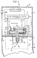
- Figure 2 illustrates a part-sectional view through one example of a dispensing device embodying the invention.
- the housing 3 of the dispensing device 1a has an internal wall 6 which separates first and second chambers 3a and 3b of the housing.
- the first chamber 3a accommodates a voltage source 20 which may be, for example, a conventional battery and a conventional electromagnetic high voltage multiplier of the type manufactured by Brandenburg, Astec Europe, of High Street, Wollaston, Stourbridge, West Midlands DY8 4PG, UK, or Start Spellman of Unit 1, Broomers Park, Broomers Hill Lane, Pulborough, West Wales RH20 2RY, UK or a piezoelectric high voltage source such as described in, for example, WO95/32807.
- a voltage source 20 which may be, for example, a conventional battery and a conventional electromagnetic high voltage multiplier of the type manufactured by Brandenburg, Astec Europe, of High Street, Wollaston, Stourbridge, West Midlands DY8 4PG, UK, or Start Spellman of Unit 1, Broomers Park, Broomers Hill Lane, Pulborough, West Wales RH20 2RY, UK or
- the voltage source 20 is coupled to a voltage generator and control circuit 21 which is arranged to derive from the voltage source the various voltages required by the dispensing device as will be described below.
- a voltage generator and control circuit 21 which is arranged to derive from the voltage source the various voltages required by the dispensing device as will be described below.
- a microprocessor or similar control circuit so as to determine the exact value and timings of the various voltages to be described below, in practice a relatively simple control circuit may be used in which one or more resistor-capacitor integrator networks and/or potential dividers are used to smoothly ramp up the voltage to that required.
- resistor-capacitor integrator networks and/or potential dividers are used to smoothly ramp up the voltage to that required.
- other known forms of voltage ramping arrangements may be used.
- a reservoir 30 of the liquid to be dispensed is coupled via an electrically insulating supply pipe 31 to a chamber 32.
- the pipe should be made of an insulating material which does not retain charge for any significant length of time.
- a suitable material is, for example, polyacetyl or Delrin (trade mark).
- the reservoir may be a collapsible reservoir, for example the liquid may be contained within a flexible collapsible bag, or may have an internal wall arranged to move with the liquid to avoid or at least reduce air contact with the liquid.
- Liquid may be supplied to the chamber 32 from the reservoir 30 by, for example, gravity feed.
- the chamber 32 may comprise a pump such as an electrohydrodynamic pump as described in EP0-A-0029301 or an electroosmotic pump of the type described with reference to Figures 6 and 7 of WO94/12285 or any other suitable form of electrically operated pump operable under the control of the control circuit 30 so as to enable a steady flow of liquid from the chamber 32.
- a pump such as an electrohydrodynamic pump as described in EP0-A-0029301 or an electroosmotic pump of the type described with reference to Figures 6 and 7 of WO94/12285 or any other suitable form of electrically operated pump operable under the control of the control circuit 30 so as to enable a steady flow of liquid from the chamber 32.
- the chamber 32 is coupled to a liquid supply pipe 33 which passes from the first chamber 3a and through the wall 6 into the second chamber 3b of the dispensing device.
- a comminution site 40 is provided at the end of the supply pipe 33.
- the comminution site is provided by the tip 41a of an electrically conductive rod 41 which extends axially through the liquid supply pipe 33 so that the tip 41a is located adjacent the outlet 33a of the supply pipe 33.
- the electrically conductive rod may have an insulative coating or sleeve so that only the tip 41a is exposed.
- a discharge electrode arrangement 50 is mounted to the wall 6 so as to extend into the second chamber 3b and so as to be spaced from the comminution site 40 in a direction which is generally transverse to the general direction in which liquid issues from the supply pipe 33.
- the discharge electrode arrangement 50 provides, as will be described below, one or more discharge points or a discharge line which are or is spaced from the comminution site in a direction radially of the supply pipe 33 but located at about the same location as the comminution site in the axial direction of the supply pipe 33.
- the discharge points may be arranged so as to point in the same direction as the comminution site or may be angled towards the comminution site.
- a further electrode 60 is positioned so as to be separated from the comminution site 40 by the discharge electrode 50.
- the discharge electrode 50 and further electrode 60 are concentrically disposed with respect to the comminution site so that the discharge electrode 50 surrounds the comminution site 40 and is in turn surrounded by the further electrode 60.
- the further electrode may extend as far as the outlet 4 of the housing.
- the further electrode 60 comprises a perforate electrically conductive or semiconductive body which may, effectively, form an inner wall of the second chamber 3b so as to bound a comminution chamber or area 3c of the device.
- the further electrode 60 may comprise a tube or cage of wire mesh.
- the wall 7 of the second chamber 3b is formed with one or more apertures 8 to allow air to enter the second chamber 3b.
- the apertures may be symmetrically disposed around the comminution site so as to facilitate a symmetrical air flow.
- the comminution site 40, discharge electrode 50 and further electrode 60 are connected to respective voltage outputs 22, 23 and 24 of the voltage generator and control circuit 21 which is arranged to provide respective voltages so that the voltage applied to the further electrode 60 is intermediate the voltages applied to the comminution site 40 and the discharge electrode 50.
- the circuit 21 is arranged to supply a negative voltage to the comminution site 40, a positive voltage to the discharge electrode 50 and earth or ground potential to the further electrode 60.
- the further electrode 60 has the further advantage of shielding the comminution chamber 3c from external electromagnetic fields so that the electrical fields within the device are not detrimentally affected when, for example, the device is held by a user.
- the voltage source 20 is coupled to the voltage generator and control circuit 21 by means of a user operable switch SW1 which may be, for example, a conventional toggle or push button switch.
- the supply pipe 31 from the reservoir 30 may be coupled to the chamber 32 by means of a valve 34.
- a further valve 35 may be provided in the supply pipe 33 adjacent the comminution site 40 to inhibit loss of liquid (which loss may occur by evaporation if the liquid being dispensed is volatile) when comminution is not occurring.
- valves 34 and 35 are electrically operated valves, for example solenoid or piezoelectric valves which are operated under the control of the control circuit 21.
- valves for example solenoid or piezoelectric valves which are operated under the control of the control circuit 21.
- simple one-way mechanical valves and, as will be described below, other mechanical valve arrangements are also possible.
- the user 2 places the mask over their nose and mouth, grasps the housing 3 of the dispensing device in their hand as shown schematically in Figure 1 and actuates the switch SW1 with their thumb or a finger and then breaths in.
- the switch SW1 couples the voltage source 20 to the voltage generator and control circuit 21 which supplies a voltage signal to open the valve 34 to allow liquid to be supplied via the chamber 32 and the supply pipe 33 to the comminution site 40.
- control circuit 21 also supplies the required voltage signals to activate the pump to supply the liquid to the supply pipe 33.
- the voltage generator and control circuit 21 outputs the negative and positive voltages on the voltage supply lines 22 and 23 and couples the further electrode 60 to, in this example, earth.
- the electric field adjacent the comminution site 40 causes atomization of the liquid supplied to the comminution site so resulting in a spray or jet 42 of charged droplets.
- air is entrained through the apertures 8 in the second chamber 3b and through the perforate further electrode 60 into the comminution chamber bounded by the further electrode 60.
- This general movement of air through the perforate electrode 60 hinders or inhibits charged liquid droplets or other charged comminution products from impacting on the electrode 60.
- the voltage applied to the discharge electrode 50 results, by corona discharge, in ionization of air or other gas molecules within the second chamber 3b to produce ions oppositely charged to the liquid droplets.
- the oppositely charged air or gas ions are attracted away from the liquid spray 42 toward the more negatively charged (in this case earthed) further electrode 60.
- the space charge resulting from the generation of the liquid droplet spray 42 eventually becomes sufficient to attract the ions away from their normal path and towards the liquid droplet spray 42 so enabling the charge on the liquid droplets to be at least partially discharged by the oppositely charged air or gas molecules produced by the discharge electrode 50 so that the liquid droplets breathed in by the user are at least partially discharged.
- the use of the further electrode 60 spaced from the comminution site 40 by the discharge electrode 50 enables the discharge electrode 50 to be placed relatively close to the comminution site 40 without the gaseous ions produced by the discharge electrode interfering with the comminution process.
- the distance between the discharge electrode and the comminution site will be greater than, for example about twice, the distance between the discharge electrode and the further electrode 60.
- the actual relative distances are selected in combination with the respective voltages applied to the electrodes 50 and 60 and the comminution site 40 so as to ensure that gaseous ions are diverted toward the further electrode 60 until a sufficient cloud of charged liquid droplets has been generated and to ensure efficient discharge:
- the discharge electrode 50 may be as close as 6-12mm to the comminution site. This allows the device structure to be particularly compact so that the comminution and discharging arrangement may have, for example, a height of about 40mm and a diameter of about 30mm making it particularly suitable for hand-held use and for transportation in a handbag or a user's pocket.
- Charged liquid droplets produced by electrohydrodynamic comminution have a charge-to-mass ratio corresponding roughly to the Rayleigh Criterion for charged droplet stability, namely: where r is the droplet radius in metres, ⁇ is the relative permittivity, ⁇ is the liquid's surface tension, and q the charge on the droplet. Accordingly by controlling the voltage applied to the comminution site, the charge and thus the radius of the liquid droplet can be controlled.
- the discharge electrode arrangement may be arranged either to fully or partially electrically discharge the charged liquid.droplets by adjusting the voltage applied to the discharge electrode in accordance with the voltage applied to the comminution site and the resistivity and flow rate of the liquid being comminuted so that the number of ionised air molecules produced by the discharge electrode is sufficient to either fully or partially discharge the comminuted material.
- Figure 4 is a part-cross sectional view similar to Figure 2 showing part of another example of a dispensing device 1a embodying the invention.
- the dispensing device shown in Figure 4 has a voltage source 20, voltage generator and control circuit 21, comminution site 40, discharge electrode 50 and further electrode 60 which are arranged in and operate in a similar manner to the corresponding components described with reference to Figure 2 when the switch SW1 is operated by a user in the manner discussed above.
- the dispensing device shown in Figure 4 differs from that shown in Figure 2 in the manner in which a liquid to be dispensed is supplied to the comminution site 40.
- liquid to be dispensed is retained in a collapsible reservoir 45 which may be in the form of a flexible bag or may have a bellows type arrangement.
- the collapsible reservoir 45 has an outlet pipe 46 which is received in a fluid-tight manner within an inlet pipe 56 of a pump chamber 32a which may be integrally formed with, for example moulded with, the supply tube 33 for supplying liquid to the comminution site 40.
- a flexible diaphragm 57 is mounted in a fluid-tight manner into an aperture in an upper portion of the pump chamber 32a.
- the periphery of the flexible diaphragm 57 is, in the arrangement shown, held between twin flanges 55a and 55b bounding the aperture.
- O-ring or similar seals 58 may be provided to ensure a fluid-tight seal.
- the flexible diaphragm may be positioned in place during the moulding process.
- the flexible diaphragm is caused to flex under the control of a diaphragm control member 59 when a voltage supplied by the control circuit 21 to the diaphragm control member 59 reaches a predetermined value.
- the diaphragm control member 59 may be, for example, a piezoelectric element formed by a ceramic disc on a metal plate such as is available commercially from Morgan Matroc Ltd., of Bewdley Road, Stourport-on-Severn, Worcestershire DY13 7QR, UK.
- a piston arrangement or a magnetically or electrostatically coupled lever system may be used.
- the conductive rod 41 which provides the comminution site 40 is pivotally mounted to and depends from a support arm 61 which is pivotally mounted at one end to a pivot mount 62 provided on an inner wall of the pump chamber 32a.
- the other end of the support arm 61 carries a valve member 35a for closing the outlet pipe 46 from the flexible reservoir 45.
- the support arm 61 is supported adjacent the pivot mount 62 by a support bar 63 which itself is mounted at one end of a piezoelectric element 64 having its other end fixedly secured to a base wall of the pump chamber 32a.
- the piezoelectric element 64 will normally have a thin and flexible resistive coating to insulate it from the liquid in the pumping chamber.
- the piezoelectric element 64 preferably comprises a piezoelectric bimorph formed of a plurality of layers of ceramic which provides a greater degree of movement for a given applied voltage than a single piezoelectric ceramic layer.
- Such piezoelectric bimorphs are also commercially available from Morgan Matroc.
- the piezoelectric element 64 flexes or bends so raising the rod 41 to cause the valve head 35a to close the outlet pipe 46 of the reservoir 45 and to move the free end of the rod 41 away from the outlet 33a of the supply pipe 33 to bring the device into the condition shown in Figure 4.
- the piezoelectric element 59 causes the diaphragm 57 to flex downwardly in Figure 4 so forcing the liquid in the pump chamber 32a to flow toward the outlet of the supply pipe 33 at a steady flow rate.
- the voltage generator and control circuit 21 applies voltages to the comminution site 40, discharge electrode 50 and further electrode 60 in the same manner as described with reference to Figures 2, 3a and 3b so resulting in a spray of charged droplets which are then discharged by the discharge electrode 50 and pass, by the action of the user breathing in, through the outlet 4 of the device into the upper respiratory system of the user.
- the control circuit may be a microprocessor or resistor-capacitor RC network control circuit.
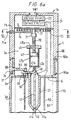
- Figure 6a shows a part-cross sectional view similar to Figures 2 and 4 of part of another dispensing device embodying the invention.
- liquid to be dispensed is contained in a syringe 47 having its capillary tube outlet 47a coupled to a liquid guiding funnel arrangement 48 for guiding liquid to the liquid supply pipe 33 which is, in this example, mounted to or integrally formed with the wall 6 dividing the first chamber 3a from the second chamber 3b.
- the syringe body 47 is mounted to a nut 49 provided with an air vent 49a. Although not shown, the nut is itself secured in a conventional manner to the wall of the upper or first chamber 3a.
- the syringe piston 47b is carried by a screw-threaded rod 70 which extends through and cooperates with the nut 49.
- the other end of the screw-threaded rod 70 is coupled by a uni-directional coupling 71 of conventional form to a shaft 72 rotatably mounted to an internal wall 9 of the housing which separates the voltage source 20 and control circuit 21 from the remainder of the device.
- a flat coil spring 73 has one end secured to shaft 72 and the other end secured to the inner surface of the housing.
- a lever 74 is fixed to and extends from the shaft 72.
- a free end 74a of the lever extends through a slot 75 provided in the housing so that the free end 74a of the lever 74 can be gripped by a user.
- the lever 74 is movable within the slot 75 as will be described below to enable a user to wind up the spring 73.
- a cam surface 80 retains an end 41b of the rod 41 on a support 81 against the action of a biasing spring 82 so as bias the other end 41a of the rod 41 into a position closing the outlet 33a of the liquid supply pipe 33.
- the cam surface 80 is provided on a rod 83 which extends through an aperture in the housing 3 from an outer rotatable sleeve 85.
- the portion 3c of the housing forming part of the side walls of the first chamber 3a is recessed with respect to the portion 3d forming the side walls of the housing forming the second chamber 3b and has at its lower end a radially outwardly extending flange 3e provided with a lip 3f which receives an axially extending rim 85a of the sleeve 85.
- the upper end of the sleeve 85 is held in place by a separate cap member 86 forming a top part of the upper chamber and having a recess 86a for receiving an axially extending circumferential projection of the sleeve.
- the cap member may for example be secured to the housing portion 3c by adhesive.
- Figure 6b shows very schematically a cross-sectional view of the device of Figure 6a taken along line VI-VI in Figure 6b.
- Figure 6b omits all components of the device apart from the coil spring 73, the shaft 72 to which one end of the spring 73 is attached, the lever 74 and its associated aperture 75 and a stop 76.
- the user first primes the device by rotating the lever 74 in its slot 75 in the direction of the arrow A in Figure 6b and against the biasing force of the coil spring 73 so winding up the coil spring.
- the unidirectional coupling 71 prevents rotation of the piston rod 70 as the spring is being wound up.
- the stop 76 is mounted within the aperture 75 so as to engage the lever when the lever meets the stop.
- the stop 76 may comprise a spring-biassed detent which engages the lever as it rides over the stop.
- Actuation of the switch SW1 provided in the top of the cap 86 of the housing causes the control circuit to supply the required voltages to the electrodes 41, 50 and 60, as discussed above, the user then depresses a button (not shown) to release the engagement between the detent 76 and the lever 74 allowing the coil spring 73 to twist the threaded shaft of the piston rod 70 through a set angle at a set rate so that the cooperation between the piston rod 70 and nut 49 causes the piston 47b to move through the syringe 47 so that a metered amount of liquid is supplied at a steady rate from the syringe to the liquid supply pipe 33.
- the air vent 49a in the nut 49 enables air to enter the syringe to allow movement of the piston 47b.
- Liquid passing from the outlet 33a of the supply pipe 33 is atomized or comminuted by the electric field at the comminution site 40 and, once sufficient space charge has built up, the charge on the thus produced droplets is electrically discharged by ions generated by the discharge electrode 50 as described above so providing a cloud or spray of discharged droplets which can then be inhaled by the user.
- the lever 74 may be mechanically and/or electrically connected to the switch SW1 so that depression of the switch SW1 also causes the lever to be released to allow the spring 73 to move the piston, so obviating the need for a separate button.
- the user rotates the sleeve 85 to return the rod 41 to its position closing the outlet 33a of the liquid supply pipe 33.
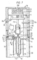
- Figure 7 is a part cross-sectional view similar to Figure 6a of part of a further example of a device embodying the invention.
- the device shown in Figure 7 is identical in operation to that shown in Figure 6a except in the manner in which liquid is supplied to the supply pipe 33.
- the syringe 47 has a reciprocable piston 47b.
- the free end of the piston rod 70a is mounted to a support plate 77 which is held in a first position against the biassing action of a spring 73a by a spring-biassed latch 78.
- the latch 78 is pivotally mounted to the housing 3 and has a portion 78a extending through an aperture in the housing 3 to form a user operable switch so that when, after having rotated the rotatable sleeve 85 to open the outlet 33a and actuated the switch SW1, the user presses downwardly on the portion 78a the latch 78 is pivoted upwardly past the edge of the support plate 77 thus freeing the support plate and allowing it to move downwardly, under the action of the spring 73a until the plate 77 meets a support member 79.
- This causes the piston to supply a metered dose of liquid to the outlet 33a where the liquid is electrohydrodynamically comminuted as described above.
- the actual amount of the dose ,supplied is determined by the location of the support member 79.
- the support member 79 is slidably mounted in a slideway 79a defined in the wall of the housing 3 and in order to reprime the device, the user grasps a free end 79b of the support member 79 and moves it upwardly in the slideway 79a so causing the support plate 77 to move upwardly in Figure 7 forcing the latch 78 to pivot upwardly against its spring biassing so that the support plate 77 comes to rest on the latch 78 as shown in Figure 7.
- the liquid in the syringe is replenished by supply through a one-way valve (not shown) from a collapsible reservoir 45 of similar type to that shown in Figure 4.
- any suitable form of biassing and latching mechanism may be used to control movement of the piston in the device shown in Figure 7.
- the device shown in Figure 6a may be modified so as to provide a reciprocating piston arrangement by removing the uni-directional coupling and providing the collapsible reservoir 45.
- a combination of electrically and mechanically operated arrangements may be used so that, for example, a mechanical outlet valve of the type shown in Figures 6a and 7 may be used in combination with an electrically operated outlet valve or alternatively an electrical pumping arrangement may be used with a mechanical outlet valve.
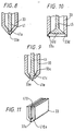
- the comminution site is provided by a rod 41 which extends through the liquid supply pipe 33 and cooperates with the liquid supply pipe so as to form a valve closing the liquid supply pipe opening 33a when supply of liquid from the liquid supply pipe is not required.
- the end 41a of the rod 41 and the opening 33a of the liquid supply pipe 33 may be shaped so as to improve the liquid tightness of the valve when closed.
- the rod 41 may be provided with a conical, i.e. sharpened or pointed, end 41a and the opening 33a of the liquid supply pipe may be arranged to be frusto-conical, narrowing towards the exterior so that, when the valve is closed, the conical end or tip 41a of the rod extends into the outlet opening of the liquid supply pipe.
- Figure 9 shows a further alternative arrangement wherein the rod 41 is provided with a radially extending flange 41c which, when the valve is closed, rests on a cooperating surface 33c of the outlet of the liquid supply pipe.
- Figure 10 shows a further possible arrangement which may be used in the devices shown in Figures 2, 6a and 7 wherein the rod 41 carries a conical valve head 41d which cooperates with a frusto-conical valve seat 33d provided by the opening 33a of the liquid supply pipe 33.
- the rod 41 is raised so as to close the valve and lowered to open the valve, and so would require the operation of the cam surface 80 on the biasing spring 82 shown in Figure 6a or 7 to be reversed.
- the comminution site is provided as a point by a cylindrical rod 41.
- other forms of comminution site may be used as described in, for example, WO95/26235, WO95/26234 or WO95/32807.
- the comminution site may be provided as a ring or annulus of spaced-apart comminution points each similar to the one shown in Figure 1 as described with reference to Figure 5 of WO95/32807.
- the comminution site 40 may be provided as a line rather than a point or series of points by replacing the rod 41 described above by a planar member 410 providing at its lower end a comminution site in the form of a knife edge 410a along which multiple jets will be formed in use.
- an annular comminution site may be used by providing a hollow cylinder in place of the rod 41.
- the discharge electrode or electrodes and the further electrode will preferably be rotationally symmetric and concentrically arranged with respect to the comminution site.
- the discharge electrode may similarly be provided as two elongate edges 50a as shown in Figure 12 and the further electrodes may be provided by two perforate planar members 60a disposed either side of the comminution site so as to ensure that, in use, the generated electric fields are symmetric with respect to the comminution site.
- the discharge electrode may be formed as a single discharge point or may be formed by a number of discrete discharge points which may be provided by, for example, separate discharge needles or may be provided by a discharge wire 50b held in place by conductive restraints 50c as shown schematically in Figure 13.
- liquid is supplied to the comminution site by gravity feed or by a pumping mechanism such as a flexible diaphragm or a syringe pump.
- a pumping mechanism such as a flexible diaphragm or a syringe pump.
- other pumping mechanisms may be used, for example, an electrohydrodynamic pump such as that described in EP-A-0029301 or an electroosmotic pump as described with reference to Figures 6 and 7 of WO94/12285 may be used or other forms of pump which allow a metered dose to be supplied may be used.
- the pumping action may be provided by means of a pressure system.
- the pressure system may be, for example, a spring-loaded pressure system wherein a spring applies a substantially constant pressure onto the reservoir or its movable wall forcing the reservoir to shrink at a substantially constant rate.
- the pressure system may be a so-called barrier pack system where the reservoir is located in a pressurised gas container so that the gas exerts a pressure forcing the reservoir to collapse or the movable wall to move to shrink the reservoir. Where such a pressure system is used, then a valve will normally be required at the liquid outlet to prevent leakage.
- the further electrode 60 is perforate and is spaced from the interior wall of the housing so as to enable air flow through the further electrode to inhibit impact of comminuted material or product on the further electrode. It may, however, be possible to provide the further electrode by providing an electrically conductive or semiconductive coating on the interior wall of the housing and to rely on air flow over the coating to inhibit impact of comminuted product on the further electrode. In such an arrangement, at least a major part of the interior wall of the housing may be coated and earthed which should enable particularly efficient electromagnetic shielding but at the expense of there being an increased likelihood of deposition of comminuted product onto the further electrode and thus less efficient delivery of the comminuted product.
- the dose delivered by a device embodying the invention may be adjustable.
- the relative times at which the valves 34 and 35 in Figure 2 and 35a and 41a in Figure 4 are opened may be used to control the amount of liquid delivered to the comminution site. This may be achieved by, for example, adjusting the rates at which the respective voltages are ramped up to the required voltages to actuate the valves by appropriate adjustment of the control circuit.
- Such adjustment may be carried out at a factory level by adjusting the values of the resistors and capacitors in the ramp circuit or may be controllable by a pharmacist or an end user by providing switch means for switching in or out additional resistors and capacitors to adjust the voltage ramp rates.
- the amount by which the spring is wound up or allowed to unwind may be selected by determining the circumferential extent of the slot 75 and/or the location of the abutment 76.
- the location of the abutment 76 may be selectable by a pharmacist or a doctor to adapt the device for the particular requirements of a particular patient or may be selectable by a patient to enable the patient to select the number of doses required.
- the slot 75 may be provided with a number of different discrete locations to which the abutment 76 may be moved with each location being identified by a scale on the housing as providing a given multiple of a basic dose.
- the abutment 76 and therefore the dose is selectable by the pharmacist or doctor
- the abutment may be designed so as to be fixed in position once inserted into the slot and may be, for example, colour coded to enable easy identification of the dose the device is designed to delivery.
- the delivery dose may be adjusted by, for example, adjusting the length of the slideway 79a in the factory or by providing on the slideway an abutment similar to the abutment 76 shown in Figure 6b which may be located as discussed above.
- Enabling the dose of liquid delivered to the comminution site to be controlled allows the device to be adapted for different patient requirements.
- the device may be adapted for use by an adult or a child and also for use with different drugs which may require different liquid dosages.
- the voltage applied to the further electrode 60 is arranged to be intermediate the voltages applied to the comminution site 40 and the discharge electrode 50. This requires, if one of the three electrodes is at earth or ground potential, two reference voltages.
- Figure 14 illustrates diagrammatically a modification which may be applied to any of the devices described above.
- the discharge electrode or electrodes 50 is/are coupled to a potential HV- which is negative with respect to the potential applied to the comminution site 40.
- the comminution site 40 is earthed (ground potential) and the further electrode 60 is coupled to earth via a resistance R.
- a voltage of about -6KV may be applied to the discharge electrode(s) 50 and the resistance R may be approximately 600 Megaohms.
- ions generated by the discharge electrode(s) 50 migrate directly toward the further electrode 60.
- the further electrode or cage 60 itself discharges through the resistance R causing the potential difference between the further electrode and the discharge electrode 50 to drop thereby limiting the production of ions by the discharge electrode 50.
- the potential at the further electrode 60 changes, the potential difference between the comminution site 40 and the further electrode increases inducing comminution of liquid supplied to the comminution site 40.
- the system is self-equilibrating. Not only does the potential of the further electrode 60 adjust the flow of ions from the discharge electrode 50 but also the space charge produced by charge comminuted matter issuing from the comminution site can increase the ion production as required.
- the discharge electrode(s) is at -6KV
- the resistance R is roughly 600 Megaohms
- the current through the further electrode is roughly 5 microamps
- the potential reached by the cage or further electrode 60 at equilibrium will be approximately 3KV which is ideal.
- negative ions/electrons are used to discharge the positively charged comminuted matter produced at the comminution site 40.
- This enables rapid response and allows the system to reach equilibrium rapidly.
- the arrangement shown in Figure 14 may be modified so as to work with positive ions by using a positive high voltage source in place of the negative high voltage source HV-and by reducing the resistance R to compensate for the fact that, where positive ions are used as the discharging means, their production is indirect, that is not due to electron emission at the discharge electrode but by virtue of an avalanche effect in towards the electrode.
- liquids with resistivities in the range of from 10 2 to 10 8 ohm-metres and viscosities in the range of from 1 to 250 centipoise may be comminuted by a device embodying the present invention.
- the liquid may be a melt, solution, suspension, emulsion microsuspension or microemulsion or even a gel provided that the liquid can be caused to flow at an adequate flow rate to the comminution site.
- the size of the comminuted liquid droplets produced depends on, for a given liquid, the electric field used to cause comminution and the flow rate.
- the electric field used for causing comminution and the flow rate of the liquid being comminuted are selected to produce droplets of a size suitable for delivery to the upper respiratory tract.
- droplets of a size suitable for delivery to the mouth cavity and throat area or to the nasal passages or even the small bronchi of the lungs may be provided.
- a dispensing device embodying the invention is primarily intended for use as a hand held portable device suitable for use as an inhaler for supplying a medicament to the respiratory system.
- Medicaments suitable for delivery by a device embodying the invention include bronchodilators or steroids as discussed above and others for treatment of disorders of the upper respiratory tract including disorders of the nasal mucosa and congestion and disorders of the upper respiratory tract associated with hayfever.
- Particular medicaments for use as nasal decongestants include as oxymetazoline, xylometazoline, phenylephrine, propylhexadrine, nephazoline and tetrahydrozoline and as appropriate salts thereof such as the hydrochloride salt, and formulations thereof.
- a device embodying the invention may also be suitable for oral or nasal delivery of drugs which are currently being tested as anti-migraine agents such as the triptans (for example almotriptan, eletriptan, naratriptan, rizatriptan, sumatriptan and zolmitriptan) or CP-122, 288 produced by Pfizer and Lanepitant produced by E. Lilley.
- a device embodying the invention is suitable for use as a pocket-size hand held inhaler for, for example, the occasional delivery of a medicament because its design enables the electrical discharge means and comminution site to be brought close together without impeding their function so allowing the device to be compact.
- the device should also be user friendly in that it is simple to operate, particularly for unskilled users and the infirm, because the liquid droplet spray is delivered under the control of the inhalation of the user and not with the force of a gas discharge as in conventional aerosol systems.
- a device embodying the invention may however also be used for dispensing droplets of other liquids, for example as a desktop or hand-held dispenser for dispensing olfactory system affecting substances, for example olfactory repressants or olfactory stimuli such as aromas and perfumes, insect repellents or attractants, biocides or insecticides, pesticides and other airborne products.
- olfactory repressants or olfactory stimuli such as aromas and perfumes, insect repellents or attractants, biocides or insecticides, pesticides and other airborne products.
Landscapes
- Electrostatic Spraying Apparatus (AREA)
- Structures Of Non-Positive Displacement Pumps (AREA)
- Water Treatment By Electricity Or Magnetism (AREA)
- Control And Other Processes For Unpacking Of Materials (AREA)
- Sampling And Sample Adjustment (AREA)
- Encapsulation Of And Coatings For Semiconductor Or Solid State Devices (AREA)
- Coating Apparatus (AREA)
Claims (37)
- Abgabevorrichtung mit:einer Zerkleinerungseinrichtung (40) zum Anlegen eines elektrischen Feldes an eine Flüssigkeit, um eine Zerkleinerung der Flüssigkeit zum Herstellen von geladenem zerkleinerten Material zu bewirken;einer Zuführeinrichtung (30, 33) zum Zuführen von Flüssigkeit zu der Zerkleinerungseinrichtung;einer elektrischen Entladungseinrichtung (50) zum Erzeugen von Ionen, um von der Zerkleinerungseinrichtung hergestelltes zerkleinertes Material wenigstens teilweise elektrisch zu entladen; undeiner von der Zerkleinerungseinrichtung durch die elektrische Entladungseinrichtung beabstandeten Ionenanzieheinrichtung (60) zum elektrischen Anziehen von von der elektrischen Entladungseinrichtung hergestellten Ionen weg von der Zerkleinerungseinrichtung bis von der Zerkleinerungseinrichtung hergestelltes zerkleinertes Material genügend Raumladung aufbaut, um die Ionen in Richtung des geladenen zerkleinerten Materials abzulenken, so daß die Ionen im Stande sind, das zerkleinerte Material wenigstens teilweise zu entladen.
- Vorrichtung nach Anspruch 1, wobei die elektrische Entladungseinrichtung (50) in Abstand von der Zerkleinerungseinrichtung (40) in einer Richtung angeordnet ist, die quer zur generellen Richtung der Zuführung zerkleinerten Materials aus der Zerkleinerungseinrichtung steht.
- Vorrichtung nach Anspruch 1, wobei die elektrische Entladungseinrichtung (50) die Zerkleinerungseinrichtung (40) umgibt oder auf jeder ihrer Seiten angeordnet ist.
- Vorrichtung nach Anspruch 1, 2 oder 3, wobei die Ionenanzieheinrichtung (60) die elektrische Entladungsvorrichtung (50) umgibt oder auf jeder ihrer Seite angeordnet ist.
- Abgabevorrichtung umfassend ein Gehäuse mit einem Auslaß zum Zuführen von zerkleinertem Material, wobei das Gehäuse enthält:eine Zerkleinerungseinrichtung (40) zum Anlegen eines elektrischen Feldes an eine Flüssigkeit, um eine Zerkleinerung der Flüssigkeit zum Herstellen einer Wolke aus geladenem zerkleinerten Material in einer Zerkleinerungskammer innerhalb des Gehäuses zu bewirken;eine Zuführeinrichtung (30, 33) zum Zuführen von Flüssigkeit zu der Zerkleinerungseinrichtung;eine die Zerkleinerungseinrichtung wenigstens teilweise umgebende elektrische Entladungseinrichtung (50) zum Erzeugen von Ionen, um von der Zerkleinerungseinrichtung hergestelltes zerkleinertes Material wenigstens teilweise elektrisch zu entladen; undeine von der Zerkleinerungseinrichtung durch die elektrische Entladungseinrichtung beabstandete und die Zerkleinerungskammer begrenzende Ionenanzieheinrichtung (60) zum elektrischen Anziehen von von der elektrischen Entladungseinrichtung hergestellten Ionen weg von der Zerkleinerungseinrichtung bis von der Zerkleinerungseinrichtung hergestelltes zerkleinertes Material genügend Raumladung aufbaut, um die Ionen in Richtung der Wolke von geladenem zerkleinerten Material abzulenken, so daß die Ionen im Stande sind, das zerkleinerte Material wenigstens teilweise zu entladen;eine Einrichtung (8), um Luft Einlaß in die Zerkleinerungskammer zu gewähren; undeine Spannungsversorgungseinrichtung zum Versorgen der Zerkleinerungseinrichtung, der elektrischen Entladungseinrichtung und der Ionenanzieheinrichtung mit elektrischen Potentialen.
- Vorrichtung nach einem der vorstehenden Ansprüche, wobei die Ionenanzieheinrichtung (60) eine elektrisch leitende oder halbleitende Perforationswand aufweist.
- Vorrichtung nach einem der vorstehenden Ansprüche, wobei die Ionenanzieheinrichtung (60) einen elektrisch leitenden oder halbleitenden Überzug auf einer Innenfläche eines Gehäuses (3) der Vorrichtung aufweist.
- Vorrichtung nach Anspruch 5, wobei die Ionenanzieheinrichtung (60) eine elektrisch leitende oder halbleitende Innenwand in Abstand von einer Innenfläche des Gehäuses aufweist, die perforiert ist und zusammen mit wenigstens einem innerhalb des Gehäuses vorgesehenem Lufteinlaß (8) die Einrichtung bildet, um Luft Einlaß in die Zerkleinerungskammer zu gewähren, so daß das Auftreffen von zerkleinertem Material auf die elektrisch leitende oder halbleitende Innenwand reduziert wird.
- Vorrichtung nach einem der vorstehenden Ansprüche, wobei in einer generellen Richtung der Herstellung zerkleinerten Materials aus der Zerkleinerungseinrichtung (40) die elektrische Entladungseinrichtung in etwa an derselben Position wie die Zerkleinerungseinrichtung angeordnet ist.
- Vorrichtung nach einem der vorstehenden Ansprüche, wobei die elektrische Entladungseinrichtung (50) mehrere elektrische Entladungsstellen aufweist, die hinsichtlich der Zerkleinerungseinrichtung symmetrisch verteilt sind.
- Vorrichtung nach einem der vorstehenden Ansprüche, wobei die Zerkleinerungseinrichtung (40) mehrere Zerkleinerungsstellen aufweist.
- Vorrichtung nach einem der vorstehenden Ansprüche, wobei die Anordnung der Zerkleinerungseinrichtung (40), der elektrischen Entladungseinrichtung (50) und der Ionenanzieheinrichtung (60) rotationssymmetrisch zu der elektrischen Entladungseinrichtung ist, und die Ionenanzieheinrichtung auf zugehörigen konzentrischen Kreisen bezüglich der Zerkleinerungseinrichtung angeordnet ist.
- Vorrichtung nach einem der Ansprüche 1 bis 11, wobei die Zerkleinerungseinrichtung (40) eine Anordnung von Zerkleinerungsstellen aufweist, und die Entladungseinrichtung (50a) und die Ionenanzieheinrichtung (60a) jeweils ein Paar länglicher Elektroden (60a) oder Elektrodenanordnungen auf jeder Seite der Zerkleinerungsstellenanordnung aufweisen.
- Vorrichtung nach einem der vorstehenden Ansprüche, wobei die Flüssigkeitszuführeinrichtung eine Pumpe zum Zuführen von Flüssigkeit von einem Flüssigkeitsreservoir (45) zu der Zerkleinerungseinrichtung aufweist.
- Vorrichtung nach Anspruch 14, wobei die Pumpe eine Membranpumpe, eine elektroosmotische Pumpe oder eine elektrohydrodynamische Pumpe aufweist.
- Vorrichtung nach Anspruch 14, wobei die Pumpe eine flexible Membran (57) aufweist, die zur Biegung in Reaktion auf das Anwenden eines Steuersignals an eine Membransteuereinrichtung (59) ausgelegt ist.
- Vorrichtung nach Anspruch 16, wobei die Membransteuereinrichtung ein piezoelektrisches Element (59) aufweist.
- Vorrichtung nach Anspruch 14, wobei die Pumpe einen Spritzenkörper (47) und einen Spritzenkolben (47b) aufweist, und eine von einem Benutzer zu bedienende Einrichtung zum Bewegen des Kolbens vorgesehen ist, um die Abgabe einer Flüssigkeitsmenge an die Zerkleinerungseinrichtung zu bewirken.
- Vorrichtung nach Anspruch 18, wobei die von einem Benutzer bedienbare Einrichtung einen Federvorspannmechanismus (73) aufweist.
- Vorrichtung nach einem der vorstehenden Ansprüche, wobei die Abgabevorrichtung ein flexibles oder zusammenlegbares Flüssigkeitsreservoir (45) aufweist.
- Vorrichtung nach Anspruch 14, wobei die Pumpe eine Einrichtung zum Anwenden eines Drucks auf einen beweglichen/zusammenlegbaren oder verformbaren Bereich eines Flüssigkeitsreservoirs (45) aufweist, um das Reservoir zu verkleinern.
- Vorrichtung nach Anspruch 21, wobei die Druckanwendeeinrichtung ein Feder- oder Gasdrucksystem aufweist.
- Vorrichtung nach einem der vorstehenden Ansprüche, ferner mit einer Einrichtung zum Steuern der zu der Zerkleinerungseinrichtung zugeführten Flüssigkeitsmenge.
- Vorrichtung nach Anspruch 19 oder 20 mit einer Einrichtung zum Steuern des Bewegungsausmaßes des Kolbens, um die zu der Zerkleinerungsstelle zugeführte Flüssigkeitsmenge zu steuern.
- Vorrichtung nach Anspruch 23 oder 24, wobei die Steuereinrichtungen anpaßbar sind, um die zu der Zerkleinerüngseinrichtung zugeführte Flüssigkeitsmenge manuell anzupassen.
- Vorrichtung nach einem der Ansprüche 16 bis 25, ferner mit einer Ventileinrichtung (34) zum Steuern der Zufuhr von Flüssigkeit von dem Reservoir zu der Pumpenkammer.
- Vorrichtung nach einem der vorstehenden Ansprüche, wobei die Ventileinrichtung (35) zum Steuern eines Flüssigkeitsauslasses zu der Zerkleinerungseinrichtung vorgesehen ist.
- Vorrichtung nach Anspruch 27, wobei die Zerkleinerungseinrichtung (40) einen Stab (41) umfaßt, der wenigstens ein elektrisch leitfähiges Ende aufweist, durch ein elektrisch isolierendes Flüssigkeitszufuhrrohr verläuft und mit einem Auslaß des Flüssigkeitszufuhrrohrs zum Bilden der Ventileinrichtung zusammenwirkt, wobei eine Einrichtung zum Bewegen des Stabs relativ zu dem Rohr vorgesehen ist, um die Ventileinrichtung für die Zufuhr von Flüssigkeit zur Zerkleinerung zu öffnen.
- Vorrichtung nach Anspruch 27, wobei die Ventileinrichtung dazu ausgelegt ist, durch ein piezoelektrisches Element und/oder ein mechanisch, magnetisch oder elektronisch gekoppeltes Hebelsystem betrieben zu werden.
- Vorrichtung nach einem der Ansprüche 1 bis 29, wobei die Ionenanzieheinrichtung (60) dazu ausgelegt ist, auf einem Potential zu liegen, das zwischen dem der Zerkleinerungseinrichtung und dem der elektrischen Entladungseinrichtung bei Benutzung liegt.
- Vorrichtung nach einem der Ansprüche 1 bis 30, wobei die Zerkleinerungseinrichtung (40) mit einer ersten Referenzpotentialquelle verbunden ist, die Ionenanzieheinrichtung (60) mit der ersten Referenzpotentialquelle über einen Widerstand verbunden ist und die elektrische Entladungseinrichtung (50) mit einer zweiten, verschiedenen Referenzpotentialquelle verbunden ist.
- Vorrichtung nach Anspruch 31, wobei das zweite Referenzpotential bezüglich des ersten Referenzpotentials negativ ist.
- Vorrichtung nach einem der vorstehenden Ansprüche mit einer Steuereinrichtung, um die Zufuhr von Flüssigkeit zu der Zerkleinerungseinrichtung vor dem Betreiben der Zerkleinerungseinrichtung zu bewirken.
- Inhaliergerät mit einer Vorrichtung nach einem der vorstehenden Ansprüche und einer Einrichtung zum Liefern von wenigstens teilweise elektrisch entladenem, zerkleinertem Material zum Atmungssystem eines Lebewesens.
- Verfahren zum Liefern eines Medikaments zum Atmungssystem eines Lebewesens, wobei eine Vorrichtung gemäß einem der Ansprüche 1 bis 33 verwendet wird, um zerkleinertes Material zu dem Atmungssystem des Lebewesens zu liefern.
- Abgabevorrichtung mit einer Vorrichtung nach einem der Ansprüche 1 bis 33 oder einem Inhaliergerät nach Anspruch 34, mit einer Versorgung mit einer das olfaktorische System beeinflussenden Substanz wie einem olfaktorischen Hemmer oder einem olfaktorischen Stimulans wie einem Aroma oder Parfüm.
- Abgabevorrichtung nach einem der Ansprüche 1 bis 33, das zum Liefern eines Insektenabwehrmittels, eines Insektenlockmittels, eines Biozids, eines Insektizids, eines Pestizids oder eines anderen in Luft schwebenden Produkts ausgelegt ist.
Applications Claiming Priority (3)
| Application Number | Priority Date | Filing Date | Title |
|---|---|---|---|
| GB9716888A GB2327895B (en) | 1997-08-08 | 1997-08-08 | A dispensing device |
| GB9716888 | 1997-08-08 | ||
| PCT/GB1998/002385 WO1999007478A1 (en) | 1997-08-08 | 1998-08-07 | A dispensing device |
Publications (2)
| Publication Number | Publication Date |
|---|---|
| EP1015128A1 EP1015128A1 (de) | 2000-07-05 |
| EP1015128B1 true EP1015128B1 (de) | 2004-01-14 |
Family
ID=10817256
Family Applications (1)
| Application Number | Title | Priority Date | Filing Date |
|---|---|---|---|
| EP98938764A Expired - Lifetime EP1015128B1 (de) | 1997-08-08 | 1998-08-07 | Abgabevorrichtung |
Country Status (12)
| Country | Link |
|---|---|
| US (1) | US6595208B1 (de) |
| EP (1) | EP1015128B1 (de) |
| JP (1) | JP4354112B2 (de) |
| CN (1) | CN1153627C (de) |
| AT (1) | ATE257746T1 (de) |
| AU (1) | AU736887B2 (de) |
| CA (1) | CA2300294C (de) |
| DE (1) | DE69821124T2 (de) |
| GB (1) | GB2327895B (de) |
| NZ (1) | NZ502599A (de) |
| RU (1) | RU2213628C2 (de) |
| WO (1) | WO1999007478A1 (de) |
Families Citing this family (91)
| Publication number | Priority date | Publication date | Assignee | Title |
|---|---|---|---|---|
| GB9225098D0 (en) | 1992-12-01 | 1993-01-20 | Coffee Ronald A | Charged droplet spray mixer |
| US6105571A (en) | 1992-12-22 | 2000-08-22 | Electrosols, Ltd. | Dispensing device |
| US6252129B1 (en) | 1996-07-23 | 2001-06-26 | Electrosols, Ltd. | Dispensing device and method for forming material |
| US7193124B2 (en) | 1997-07-22 | 2007-03-20 | Battelle Memorial Institute | Method for forming material |
| US6433154B1 (en) * | 1997-06-12 | 2002-08-13 | Bristol-Myers Squibb Company | Functional receptor/kinase chimera in yeast cells |
| GB2327895B (en) | 1997-08-08 | 2001-08-08 | Electrosols Ltd | A dispensing device |
| US6397838B1 (en) * | 1998-12-23 | 2002-06-04 | Battelle Pulmonary Therapeutics, Inc. | Pulmonary aerosol delivery device and method |
| KR20020005721A (ko) * | 1999-04-23 | 2002-01-17 | 추후기재 | 하이 매스 전달 전기분무기 |
| DE60024992T2 (de) * | 1999-04-23 | 2006-08-24 | Battelle Memorial Institute, Columbus | Richtungsverstellbarer ehd- aerosol-zerstäuber |
| EP1173245B1 (de) | 1999-05-03 | 2004-09-01 | Battelle Memorial Institute | Arzneizusammensetzungen zur aerosolbildung und zu inhalationszwecken |
| US9006175B2 (en) | 1999-06-29 | 2015-04-14 | Mannkind Corporation | Potentiation of glucose elimination |
| US7712687B2 (en) * | 1999-08-18 | 2010-05-11 | The Procter & Gamble Company | Electrostatic spray device |
| AU2001244391B9 (en) * | 2000-04-03 | 2006-10-05 | Ventaira Pharmaceuticals, Inc. | Devices and formulations |
| US6764720B2 (en) * | 2000-05-16 | 2004-07-20 | Regents Of The University Of Minnesota | High mass throughput particle generation using multiple nozzle spraying |
| WO2002043750A2 (en) * | 2000-12-01 | 2002-06-06 | Battelle Memorial Institute | Method for the stabilizing of biomolecules (e.g. insulin) in liquid formulations |
| CA2440763C (en) * | 2001-03-22 | 2010-05-25 | Battelle Memorial Institute | Liquid formations for electrohydrodymanic spraying containing polymer and suspended particles |
| US20020168297A1 (en) * | 2001-05-11 | 2002-11-14 | Igor Shvets | Method and device for dispensing of droplets |
| US7247338B2 (en) * | 2001-05-16 | 2007-07-24 | Regents Of The University Of Minnesota | Coating medical devices |
| MXPA04006629A (es) * | 2002-01-07 | 2004-11-10 | Aerogen Inc | Aparatos y metodos para nebulizar fluidos para inhalacion. |
| EP1494732B1 (de) | 2002-03-20 | 2008-01-30 | MannKind Corporation | Inhalationsgerät |
| US7849850B2 (en) * | 2003-02-28 | 2010-12-14 | Battelle Memorial Institute | Nozzle for handheld pulmonary aerosol delivery device |
| US7231839B2 (en) * | 2003-08-11 | 2007-06-19 | The Board Of Trustees Of The Leland Stanford Junior University | Electroosmotic micropumps with applications to fluid dispensing and field sampling |
| EP1781414B1 (de) * | 2004-02-09 | 2008-11-12 | Matsushita Electric Works, Ltd | Elektrostatische sprühvorrichtung |
| US7841549B2 (en) * | 2004-02-09 | 2010-11-30 | Panasonic Electric Works Co., Ltd. | Electrostatic spraying device |
| WO2005075093A1 (en) * | 2004-02-09 | 2005-08-18 | Matsushita Electric Works, Ltd. | Electrostatic spraying device |
| WO2005075090A1 (en) * | 2004-02-09 | 2005-08-18 | Matsushita Electric Works, Ltd. | Electrostatic spraying device |
| US20050212879A1 (en) * | 2004-03-29 | 2005-09-29 | Chiao Dahshiarn | Replaceable electrostatically sprayable material reservoir for use with a electrostatic spraying device |
| US20050212870A1 (en) * | 2004-03-29 | 2005-09-29 | Chiao Dahshiarn | Replaceable electrostatically sprayable material reservoir design having electrostatic spraying and method for using same |
| US20050240162A1 (en) * | 2004-04-21 | 2005-10-27 | Wen-Pin Chen | Eye treatment device |
| DK1786784T3 (da) | 2004-08-20 | 2011-02-14 | Mannkind Corp | Katalyse af diketopiperazinsyntese |
| CN104436170B (zh) | 2004-08-23 | 2018-02-23 | 曼金德公司 | 用于药物输送的二酮哌嗪盐 |
| DE102004049574A1 (de) * | 2004-10-12 | 2006-04-20 | Doris Dr. Barnikol-Keuten | Arzneimittel und System zur perkutanen Arzneistoffverabreichung |
| KR100796308B1 (ko) | 2004-11-26 | 2008-01-21 | 마츠시다 덴코 가부시키가이샤 | 정전 스프레이 장치 |
| EP1832349A4 (de) * | 2004-12-28 | 2008-07-23 | Daikin Ind Ltd | Elektrostatische sprühvorrichtung |
| AU2006290227B2 (en) | 2005-09-14 | 2012-08-02 | Mannkind Corporation | Method of drug formulation based on increasing the affinity of crystalline microparticle surfaces for active agents |
| PL1951380T3 (pl) * | 2005-09-26 | 2019-10-31 | Univ Leeds Innovations Ltd | Wtryskiwacz paliwa |
| JP4674541B2 (ja) * | 2005-12-22 | 2011-04-20 | パナソニック電工株式会社 | 静電霧化装置及び静電霧化装置を備えた食品保管庫 |
| EP2529761B1 (de) * | 2006-01-31 | 2017-06-14 | Nanocopoeia, Inc. | Oberflächenbeschichtung mit nanoteilchen |
| US7951428B2 (en) | 2006-01-31 | 2011-05-31 | Regents Of The University Of Minnesota | Electrospray coating of objects |
| US9108217B2 (en) | 2006-01-31 | 2015-08-18 | Nanocopoeia, Inc. | Nanoparticle coating of surfaces |
| CA2649413A1 (en) | 2006-02-14 | 2007-08-23 | Battelle Memorial Institute | Dissociated discharge ehd sprayer with electric field shield |
| KR20080096809A (ko) | 2006-02-22 | 2008-11-03 | 맨카인드 코포레이션 | 디케토피페라진 및 활성제를 포함하는 마이크로입자의 약학특성의 개선 방법 |
| US7673819B2 (en) * | 2006-06-26 | 2010-03-09 | Battelle Memorial Institute | Handheld sprayer with removable cartridge and method of using same |
| USD545942S1 (en) | 2006-06-13 | 2007-07-03 | Battelle Memorial Institute | Sprayer handle |
| USD562940S1 (en) | 2006-06-13 | 2008-02-26 | Battelle Memorial Institute | Handle |
| WO2008002556A1 (en) * | 2006-06-26 | 2008-01-03 | Battelle Memorial Institute | Cartridge having self-actuating seal for a wetted lead screw |
| US7793860B2 (en) * | 2007-01-17 | 2010-09-14 | The Dial Corporation | Piston actuated vapor-dispersing device |
| US7793861B2 (en) * | 2007-01-17 | 2010-09-14 | The Dial Corporation | Piston actuated vapor-dispersing device |
| US20080217437A1 (en) * | 2007-03-06 | 2008-09-11 | Spraying Systems Co. | Optimized Method to Drive Electric Spray Guns |
| DE102007033892A1 (de) * | 2007-07-20 | 2009-01-22 | Dürr Systems GmbH | Verfahren zur Prozessdiagnose und Rotationszerstäuberanordnung |
| US8296993B2 (en) | 2007-11-16 | 2012-10-30 | Monster Mosquito Systems, Llc | Ultrasonic humidifier for repelling insects |
| US7712249B1 (en) | 2007-11-16 | 2010-05-11 | Monster Mosquito Systems, Llc | Ultrasonic humidifier for repelling insects |
| SG10201507036TA (en) | 2008-06-13 | 2015-10-29 | Mannkind Corp | A dry powder inhaler and system for drug delivery |
| US8485180B2 (en) | 2008-06-13 | 2013-07-16 | Mannkind Corporation | Dry powder drug delivery system |
| EP2609954B1 (de) | 2008-06-20 | 2021-12-29 | MannKind Corporation | Interaktives Gerät für die Echtzeit-Profilierung von Inhalationsversuchen |
| TWI614024B (zh) | 2008-08-11 | 2018-02-11 | 曼凱公司 | 超快起作用胰島素之用途 |
| US8314106B2 (en) | 2008-12-29 | 2012-11-20 | Mannkind Corporation | Substituted diketopiperazine analogs for use as drug delivery agents |
| RU2395307C1 (ru) * | 2009-01-11 | 2010-07-27 | Анатолий Анатольевич Дьяконов | Ингалятор с электронным управлением |
| MX2011009512A (es) | 2009-03-11 | 2011-11-29 | Mannkind Corp | Aparato, sistema y metodo para medir la resistencia de un inhalador. |
| MY157166A (en) | 2009-06-12 | 2016-05-13 | Mankind Corp | Diketopiperazine microparticles with defined specific surface areas |
| JP2011067771A (ja) * | 2009-09-25 | 2011-04-07 | Panasonic Electric Works Co Ltd | 放電装置 |
| CA2778698A1 (en) | 2009-11-03 | 2011-05-12 | Mannkind Corporation | An apparatus and method for simulating inhalation efforts |
| JP5429993B2 (ja) * | 2010-03-04 | 2014-02-26 | 国立大学法人東京工業大学 | 匂い発生装置 |
| IL223742A (en) | 2010-06-21 | 2016-06-30 | Mannkind Corp | A dry powder inhaler and preparation for it |
| EP2694402B1 (de) | 2011-04-01 | 2017-03-22 | MannKind Corporation | Blisterverpackung für pharmakartuschen |
| WO2012174472A1 (en) | 2011-06-17 | 2012-12-20 | Mannkind Corporation | High capacity diketopiperazine microparticles |
| UA96913C2 (uk) * | 2011-07-22 | 2011-12-12 | Лабендік Роман Едуардович | Портативний ручний пристрій для нанесення ворсового покриття на зону поверхні людського тіла |
| HK1200318A1 (en) | 2011-10-24 | 2015-08-07 | 曼金德公司 | Methods and compositions for treating pain |
| NL2008056C2 (en) * | 2011-12-29 | 2013-07-03 | Univ Delft Tech | System and method for delivering sprayed particles by electrospraying. |
| EP2872205B1 (de) | 2012-07-12 | 2017-02-08 | MannKind Corporation | System zur verabreichung von arzneimitteln in trockenpulverform |
| US10047672B2 (en) * | 2012-09-10 | 2018-08-14 | General Electric Company | Gas turbine wet compression system using electrohydrodynamic (EHD) atomization |
| US20150082689A1 (en) * | 2012-10-01 | 2015-03-26 | Jacques C. Bertrand | Small droplet sprayer |
| US10159644B2 (en) | 2012-10-26 | 2018-12-25 | Mannkind Corporation | Inhalable vaccine compositions and methods |
| WO2014144895A1 (en) | 2013-03-15 | 2014-09-18 | Mannkind Corporation | Microcrystalline diketopiperazine compositions and methods |
| KR102465025B1 (ko) | 2013-07-18 | 2022-11-09 | 맨카인드 코포레이션 | 열-안정성 건조 분말 약제학적 조성물 및 방법 |
| EP3030294B1 (de) | 2013-08-05 | 2020-10-07 | MannKind Corporation | Insufflationsvorrichtung |
| EP3054823B1 (de) * | 2013-10-11 | 2021-06-16 | Gehl Foods, LLC | Nahrungsmittelausgabevorrichtung und ventil |
| US10307464B2 (en) | 2014-03-28 | 2019-06-04 | Mannkind Corporation | Use of ultrarapid acting insulin |
| US11148164B2 (en) | 2014-07-25 | 2021-10-19 | Biodot, Inc. | Piezoelectric dispenser with a longitudinal transducer and replaceable capillary tube |
| GB201414536D0 (en) * | 2014-08-15 | 2014-10-01 | Asalus Medical Instr Ltd | A surgical spray instrument |
| US10561806B2 (en) | 2014-10-02 | 2020-02-18 | Mannkind Corporation | Mouthpiece cover for an inhaler |
| JP6480598B2 (ja) | 2015-04-02 | 2019-03-13 | ヒル−ロム サービシーズ プライヴェート リミテッド | 呼吸装置用マニホールド |
| CN105532618B (zh) * | 2016-01-08 | 2018-04-10 | 安庆市义云农业有限责任公司 | 一种用于水稻龙虾混合养殖苗田的水雾驱虫设备 |
| CN106140509A (zh) * | 2016-09-13 | 2016-11-23 | 乔大祥 | 调频式静电喷洒机和可替换式物质储存槽结合的应用 |
| US20200121867A1 (en) * | 2017-04-20 | 2020-04-23 | Victory Innovations Company | Electrostatic stem cell fluid delivery system |
| CN107537704A (zh) * | 2017-08-18 | 2018-01-05 | 广州市拓丰电器有限公司 | 一种水雾纳米气化转换装置 |
| US10851475B2 (en) * | 2017-11-21 | 2020-12-01 | Kao Corporation | Electrospinning apparatus and systems and methods thereof |
| CN108739412B (zh) * | 2018-05-17 | 2021-02-09 | 务川自治县宏牧羊业有限公司 | 病羊隔离系统 |
| US11291762B2 (en) * | 2018-10-15 | 2022-04-05 | Carefusion 303, Inc. | Microdrop drip chamber |
| KR102424736B1 (ko) * | 2021-03-23 | 2022-07-25 | 주식회사 프로텍 | 기체 유로를 구비하는 전기수력학적 펌프 헤드 조립체 |
| KR102500430B1 (ko) * | 2021-03-23 | 2023-02-16 | 주식회사 프로텍 | 튜브형 외부 전극을 구비하는 전기수력학적 펌프 헤드 조립체 |
Family Cites Families (85)
| Publication number | Priority date | Publication date | Assignee | Title |
|---|---|---|---|---|
| GB102713A (en) | 1915-12-13 | 1917-03-08 | Robert Walter Scott | Improvements in Yarn Feeding Devices for Knitting Machines. |
| US2685536A (en) * | 1944-09-29 | 1954-08-03 | Ransburg Electro Coating Corp | Method for electrostatically coating articles |
| US2749125A (en) | 1952-10-27 | 1956-06-05 | Donald F Ream | Target indicating apparatus |
| US2945443A (en) | 1957-08-22 | 1960-07-19 | Gen Electric | Pump operation |
| US3096762A (en) | 1962-02-12 | 1963-07-09 | Waterbury Pressed Metal Co | Oral breathing device |
| US3131131A (en) | 1962-04-03 | 1964-04-28 | Socony Mobil Oil Co Inc | Electrostatic mixing in microbial conversions |
| US3232292A (en) | 1962-10-12 | 1966-02-01 | Arizona Nucleonics Inc | Ionized aerosols |
| US3456646A (en) | 1967-01-19 | 1969-07-22 | Dart Ind Inc | Inhalation-actuated aerosol dispensing device |
| US3565070A (en) | 1969-02-28 | 1971-02-23 | Riker Laboratories Inc | Inhalation actuable aerosol dispenser |
| US3837573A (en) | 1972-03-02 | 1974-09-24 | W Wagner | Apparatus for electrified spraying |
| US3958959A (en) | 1972-11-02 | 1976-05-25 | Trw Inc. | Method of removing particles and fluids from a gas stream by charged droplets |
| US3897905A (en) | 1973-10-19 | 1975-08-05 | Universal Oil Prod Co | Electrostatic spraying nozzle |
| US3930061A (en) | 1974-04-08 | 1975-12-30 | Ransburg Corp | Electrostatic method for forming structures and articles |
| GB1527592A (en) | 1974-08-05 | 1978-10-04 | Ici Ltd | Wound dressing |
| US3994294A (en) * | 1975-02-28 | 1976-11-30 | Ivac Corporation | Syringe pump valving and motor direction control system |
| GB1563707A (en) | 1975-11-25 | 1980-03-26 | Ass Elect Ind | Saturated reactor arrangements |
| CA1109545A (en) | 1976-05-08 | 1981-09-22 | Nissan Motor Co., Ltd. | Electrostatic apparatus for controlling flow rate of liquid |
| US4150644A (en) | 1976-05-29 | 1979-04-24 | Nissan Motor Company, Limited | Method for controlling electrostatic fuel injectors |
| GB1569707A (en) | 1976-07-15 | 1980-06-18 | Ici Ltd | Atomisation of liquids |
| IE45426B1 (en) | 1976-07-15 | 1982-08-25 | Ici Ltd | Atomisation of liquids |
| US4073002A (en) | 1976-11-02 | 1978-02-07 | Ppg Industries, Inc. | Self-adjusting power supply for induction charging electrodes |
| US4255777A (en) | 1977-11-21 | 1981-03-10 | Exxon Research & Engineering Co. | Electrostatic atomizing device |
| GB2018627B (en) | 1978-04-17 | 1982-04-15 | Ici Ltd | Process and apparatus for spraying liguid |
| ZA791659B (en) | 1978-04-17 | 1980-04-30 | Ici Ltd | Process and apparatus for spraying liquid |
| US4198781A (en) | 1978-08-03 | 1980-04-22 | Lasco, Inc. | Plant destruction utilizing electrically conductive liquid |
| US4186886A (en) | 1978-08-04 | 1980-02-05 | Ppg Industries, Inc. | Adapting means providing detachable mounting of an induction-charging adapter head on a spray device |
| GB2030060B (en) * | 1978-09-26 | 1982-12-01 | Ici Ltd | Electrostatic spraying of liquid |
| US4266721A (en) | 1979-09-17 | 1981-05-12 | Ppg Industries, Inc. | Spray application of coating compositions utilizing induction and corona charging means |
| ATE10711T1 (de) | 1979-11-19 | 1984-12-15 | Imperial Chemical Industries Plc | Elektrostatischer spruehapparat. |
| US4401274A (en) * | 1980-03-20 | 1983-08-30 | Imperial Chemical Industries Plc | Containers for use in electrostatic spraying |
| DE3036814C2 (de) | 1980-09-30 | 1984-10-04 | Fa. Carl Freudenberg, 6940 Weinheim | Wundkompresse und Verfahren zu ihrer Herstellung |
| EP0058472B1 (de) | 1981-02-12 | 1986-04-23 | Imperial Chemical Industries Plc | Flüssigkeitszerstäuber für landwirtschaftlichen Einsatz sowie dazugehörige Vorratsbehälter |
| JPS6057907B2 (ja) | 1981-06-18 | 1985-12-17 | 工業技術院長 | 液体の混合噴霧化方法 |
| SU1005939A1 (ru) | 1981-06-29 | 1983-03-23 | Уральский научно-исследовательский институт трубной промышленности | Устройство дл электростатического напылени порошковых материалов |
| US4439980A (en) | 1981-11-16 | 1984-04-03 | The United States Of America As Represented By The Secretary Of The Navy | Electrohydrodynamic (EHD) control of fuel injection in gas turbines |
| DE3373279D1 (en) * | 1982-08-25 | 1987-10-08 | Ici Plc | Electrostatic entrainment pump for a spraying system |
| GB2128900B (en) | 1982-10-29 | 1985-11-20 | Theoktiste Christofidis | Ionising spray |
| EP0121288B1 (de) | 1983-01-06 | 1989-05-17 | National Research Development Corporation | Elektrostatischer Spritzkopf |
| EP0120633B1 (de) | 1983-03-25 | 1988-12-14 | Imperial Chemical Industries Plc | Zerstäubungseinrichtung |
| US4509694A (en) | 1983-06-01 | 1985-04-09 | Canadian Patents & Development Limited | Cross-current airfoil electrostatic nozzle |
| US4659012A (en) | 1983-08-18 | 1987-04-21 | Imperial Chemical Industries Plc | Electrostatic spraying process and apparatus |
| US4657793A (en) | 1984-07-16 | 1987-04-14 | Ethicon, Inc. | Fibrous structures |
| GB8432272D0 (en) | 1984-12-20 | 1985-01-30 | Ici Plc | Spraying apparatus |
| GB8504254D0 (en) | 1985-02-19 | 1985-03-20 | Ici Plc | Spraying apparatus |
| DE3661121D1 (en) | 1985-09-03 | 1988-12-15 | Sale Tilney Technology Plc | Electrostatic coating blade and method of electrostatic spraying |
| US4671289A (en) | 1985-11-08 | 1987-06-09 | Renco Corporation | Housing for ultrasonic detector |
| GB8604328D0 (en) | 1986-02-21 | 1986-03-26 | Ici Plc | Producing spray of droplets of liquid |
| GB8609703D0 (en) | 1986-04-21 | 1986-05-29 | Ici Plc | Electrostatic spraying |
| GB8614566D0 (en) | 1986-06-16 | 1986-07-23 | Ici Plc | Spraying |
| GB8614564D0 (en) | 1986-06-16 | 1986-07-23 | Ici Plc | Spraying |
| US4748043A (en) | 1986-08-29 | 1988-05-31 | Minnesota Mining And Manufacturing Company | Electrospray coating process |
| US4749125A (en) | 1987-01-16 | 1988-06-07 | Terronics Development Corp. | Nozzle method and apparatus |
| DE3707547A1 (de) | 1987-03-10 | 1988-09-22 | Bayer Ag | Verfahren und vorrichtung zum verspritzen von pflanzenschutzmittelloesungen oder -dispersionen |
| US4779515A (en) | 1987-05-15 | 1988-10-25 | General Motors Corporation | Vacuum brake booster with bayonet mount having snap-retained mounting arm |
| DD271611A3 (de) | 1987-10-27 | 1989-09-13 | Verkehrswesen Hochschule | Spruehpistole mit elektrokinetischer pulveraufladung |
| US5115971A (en) | 1988-09-23 | 1992-05-26 | Battelle Memorial Institute | Nebulizer device |
| US5267555A (en) | 1988-07-01 | 1993-12-07 | Philip Pajalich | Apparatus and method for ionizing medication containing mists |
| US5270000A (en) * | 1989-04-19 | 1993-12-14 | Abb Sanitec, Inc. | Apparatus and process for treating medical hazardous wastes |
| DE3925749C1 (de) | 1989-08-03 | 1990-10-31 | Fraunhofer-Gesellschaft Zur Foerderung Der Angewandten Forschung Ev, 8000 Muenchen, De | |
| US5044564A (en) | 1989-11-21 | 1991-09-03 | Sickles James E | Electrostatic spray gun |
| DE4022393A1 (de) | 1990-07-13 | 1992-01-23 | Marquardt Klaus | Ionisator zur ionisierung von sauerstoff bei sauerstoff-therapie |
| ES2071927T3 (es) | 1990-07-25 | 1995-07-01 | Ici Plc | Metodo de pulverizacion electrostatica. |
| US5086972A (en) | 1990-08-01 | 1992-02-11 | Hughes Aircraft Company | Enhanced electrostatic paint deposition method and apparatus |
| RU2008937C1 (ru) * | 1990-09-25 | 1994-03-15 | Самарская областная стоматологическая поликлиника | Ингалятор |
| DE4106564C2 (de) | 1991-03-01 | 1999-06-10 | Bosch Gmbh Robert | Vorrichtung zur elektrostatischen Zerstäubung von Flüssigkeiten |
| PT501725E (pt) * | 1991-03-01 | 2001-10-31 | Procter & Gamble | Pulverizacao de liquidos |
| US5196171A (en) | 1991-03-11 | 1993-03-23 | In-Vironmental Integrity, Inc. | Electrostatic vapor/aerosol/air ion generator |
| US5282982A (en) | 1991-07-12 | 1994-02-01 | Wells John R | Blood washing method |
| GB9115278D0 (en) | 1991-07-15 | 1991-08-28 | Unilever Plc | Liquid spraying apparatus and method |
| GB9115279D0 (en) | 1991-07-15 | 1991-08-28 | Unilever Plc | Hair and scalp treatment system |
| GB9115277D0 (en) | 1991-07-15 | 1991-08-28 | Unilever Plc | Spraying system |
| WO1994013266A1 (en) | 1992-05-29 | 1994-06-23 | The Regents Of The University Of California | Novel electrostatic process for manufacturing coated transplants and products |
| GB9225098D0 (en) | 1992-12-01 | 1993-01-20 | Coffee Ronald A | Charged droplet spray mixer |
| GB9226717D0 (en) * | 1992-12-22 | 1993-02-17 | Coffee Ronald A | Induction-operated electro-hydrodynamic spray device with means of modifying droplet trajectories |
| US6105571A (en) * | 1992-12-22 | 2000-08-22 | Electrosols, Ltd. | Dispensing device |
| US5402945A (en) | 1993-01-22 | 1995-04-04 | Gervan Company International | Method for spraying plants and apparatus for its practice |
| GB9303335D0 (en) * | 1993-02-19 | 1993-04-07 | Bespak Plc | Inhalation apparatus |
| RU2071789C1 (ru) * | 1993-05-26 | 1997-01-20 | Владимир Николаевич Абросимов | Устройство для аэрозольной терапии |
| US5409162A (en) | 1993-08-09 | 1995-04-25 | Sickles; James E. | Induction spray charging apparatus |
| GB9406255D0 (en) * | 1994-03-29 | 1994-05-18 | Electrosols Ltd | Dispensing device |
| GB9406171D0 (en) | 1994-03-29 | 1994-05-18 | Electrosols Ltd | Dispensing device |
| GB9410658D0 (en) | 1994-05-27 | 1994-07-13 | Electrosols Ltd | Dispensing device |
| US5483953A (en) | 1995-04-08 | 1996-01-16 | The United States Of America As Represented By The Secretary Of The Navy | Aerosol dispensing apparatus for dispensing a medicated vapor into the lungs of a patient |
| GB2327895B (en) | 1997-08-08 | 2001-08-08 | Electrosols Ltd | A dispensing device |
| GB0102713D0 (en) | 2001-02-02 | 2001-03-21 | Smithkline Beecham Plc | Novel compounds |
-
1997
- 1997-08-08 GB GB9716888A patent/GB2327895B/en not_active Expired - Fee Related
-
1998
- 1998-08-07 AU AU87371/98A patent/AU736887B2/en not_active Ceased
- 1998-08-07 JP JP2000507058A patent/JP4354112B2/ja not_active Expired - Fee Related
- 1998-08-07 CA CA002300294A patent/CA2300294C/en not_active Expired - Fee Related
- 1998-08-07 DE DE1998621124 patent/DE69821124T2/de not_active Expired - Lifetime
- 1998-08-07 CN CNB988100592A patent/CN1153627C/zh not_active Expired - Fee Related
- 1998-08-07 NZ NZ502599A patent/NZ502599A/en unknown
- 1998-08-07 EP EP98938764A patent/EP1015128B1/de not_active Expired - Lifetime
- 1998-08-07 AT AT98938764T patent/ATE257746T1/de not_active IP Right Cessation
- 1998-08-07 RU RU2000106031/12A patent/RU2213628C2/ru not_active IP Right Cessation
- 1998-08-07 US US09/463,264 patent/US6595208B1/en not_active Expired - Fee Related
- 1998-08-07 WO PCT/GB1998/002385 patent/WO1999007478A1/en not_active Ceased
Also Published As
| Publication number | Publication date |
|---|---|
| EP1015128A1 (de) | 2000-07-05 |
| ATE257746T1 (de) | 2004-01-15 |
| DE69821124T2 (de) | 2004-11-18 |
| GB2327895B (en) | 2001-08-08 |
| WO1999007478A1 (en) | 1999-02-18 |
| CA2300294A1 (en) | 1999-02-18 |
| GB9716888D0 (en) | 1997-10-15 |
| RU2213628C2 (ru) | 2003-10-10 |
| JP2001513423A (ja) | 2001-09-04 |
| CN1275099A (zh) | 2000-11-29 |
| AU8737198A (en) | 1999-03-01 |
| US6595208B1 (en) | 2003-07-22 |
| GB2327895A (en) | 1999-02-10 |
| CN1153627C (zh) | 2004-06-16 |
| AU736887B2 (en) | 2001-08-02 |
| NZ502599A (en) | 2001-12-21 |
| JP4354112B2 (ja) | 2009-10-28 |
| DE69821124D1 (de) | 2004-02-19 |
| CA2300294C (en) | 2009-05-26 |
Similar Documents
| Publication | Publication Date | Title |
|---|---|---|
| CA2300294C (en) | A dispensing device | |
| US6386195B1 (en) | Dispensing device | |
| EP0675764B1 (de) | Ausgabevorrichtung | |
| US6880554B1 (en) | Dispensing device | |
| US6394086B1 (en) | Inhalation apparatus | |
| JP4677102B2 (ja) | エーロゾル給送装置及びエーロゾル小滴を給送する方法 | |
| CN101316628B (zh) | 改进的配送装置和方法 | |
| CN100376297C (zh) | 鼻吸器 | |
| DK164847B (da) | Forstoevningsapparat | |
| JPH11510403A (ja) | 静電噴霧装置 | |
| AU684735C (en) | Dispensing device | |
| HK1012302B (en) | Dispensing device | |
| NZ328962A (en) | Inhaler with electrical charging and discharging for comminution and supply of liquid to user |
Legal Events
| Date | Code | Title | Description |
|---|---|---|---|
| PUAI | Public reference made under article 153(3) epc to a published international application that has entered the european phase |
Free format text: ORIGINAL CODE: 0009012 |
|
| 17P | Request for examination filed |
Effective date: 20000306 |
|
| AK | Designated contracting states |
Kind code of ref document: A1 Designated state(s): AT BE CH CY DE DK ES FI FR GB GR IE IT LI LU MC NL PT SE |
|
| 17Q | First examination report despatched |
Effective date: 20020628 |
|
| GRAH | Despatch of communication of intention to grant a patent |
Free format text: ORIGINAL CODE: EPIDOS IGRA |
|
| RAP1 | Party data changed (applicant data changed or rights of an application transferred) |
Owner name: BATTELLE MEMORIAL INSTITUTE |
|
| GRAS | Grant fee paid |
Free format text: ORIGINAL CODE: EPIDOSNIGR3 |
|
| GRAA | (expected) grant |
Free format text: ORIGINAL CODE: 0009210 |
|
| AK | Designated contracting states |
Kind code of ref document: B1 Designated state(s): AT BE CH CY DE DK ES FI FR GB GR IE IT LI LU MC NL PT SE |
|
| PG25 | Lapsed in a contracting state [announced via postgrant information from national office to epo] |
Ref country code: NL Free format text: LAPSE BECAUSE OF FAILURE TO SUBMIT A TRANSLATION OF THE DESCRIPTION OR TO PAY THE FEE WITHIN THE PRESCRIBED TIME-LIMIT Effective date: 20040114 Ref country code: IT Free format text: LAPSE BECAUSE OF FAILURE TO SUBMIT A TRANSLATION OF THE DESCRIPTION OR TO PAY THE FEE WITHIN THE PRE;WARNING: LAPSES OF ITALIAN PATENTS WITH EFFECTIVE DATE BEFORE 2007 MAY HAVE OCCURRED AT ANY TIME BEFORE 2007. THE CORRECT EFFECTIVE DATE MAY BE DIFFERENT FROM THE ONE RECORDED.SCRIBED TIME-LIMIT Effective date: 20040114 Ref country code: FI Free format text: LAPSE BECAUSE OF FAILURE TO SUBMIT A TRANSLATION OF THE DESCRIPTION OR TO PAY THE FEE WITHIN THE PRESCRIBED TIME-LIMIT Effective date: 20040114 Ref country code: CY Free format text: LAPSE BECAUSE OF FAILURE TO SUBMIT A TRANSLATION OF THE DESCRIPTION OR TO PAY THE FEE WITHIN THE PRESCRIBED TIME-LIMIT Effective date: 20040114 Ref country code: BE Free format text: LAPSE BECAUSE OF FAILURE TO SUBMIT A TRANSLATION OF THE DESCRIPTION OR TO PAY THE FEE WITHIN THE PRESCRIBED TIME-LIMIT Effective date: 20040114 Ref country code: AT Free format text: LAPSE BECAUSE OF FAILURE TO SUBMIT A TRANSLATION OF THE DESCRIPTION OR TO PAY THE FEE WITHIN THE PRESCRIBED TIME-LIMIT Effective date: 20040114 |
|
| REG | Reference to a national code |
Ref country code: GB Ref legal event code: FG4D |
|
| REG | Reference to a national code |
Ref country code: CH Ref legal event code: EP |
|
| REG | Reference to a national code |
Ref country code: IE Ref legal event code: FG4D |
|
| REF | Corresponds to: |
Ref document number: 69821124 Country of ref document: DE Date of ref document: 20040219 Kind code of ref document: P |
|
| PG25 | Lapsed in a contracting state [announced via postgrant information from national office to epo] |
Ref country code: SE Free format text: LAPSE BECAUSE OF FAILURE TO SUBMIT A TRANSLATION OF THE DESCRIPTION OR TO PAY THE FEE WITHIN THE PRESCRIBED TIME-LIMIT Effective date: 20040414 Ref country code: GR Free format text: LAPSE BECAUSE OF FAILURE TO SUBMIT A TRANSLATION OF THE DESCRIPTION OR TO PAY THE FEE WITHIN THE PRESCRIBED TIME-LIMIT Effective date: 20040414 Ref country code: DK Free format text: LAPSE BECAUSE OF FAILURE TO SUBMIT A TRANSLATION OF THE DESCRIPTION OR TO PAY THE FEE WITHIN THE PRESCRIBED TIME-LIMIT Effective date: 20040414 |
|
| PG25 | Lapsed in a contracting state [announced via postgrant information from national office to epo] |
Ref country code: ES Free format text: LAPSE BECAUSE OF FAILURE TO SUBMIT A TRANSLATION OF THE DESCRIPTION OR TO PAY THE FEE WITHIN THE PRESCRIBED TIME-LIMIT Effective date: 20040425 |
|
| REG | Reference to a national code |
Ref country code: CH Ref legal event code: NV Representative=s name: E. BLUM & CO. PATENTANWAELTE |
|
| NLV1 | Nl: lapsed or annulled due to failure to fulfill the requirements of art. 29p and 29m of the patents act | ||
| PGFP | Annual fee paid to national office [announced via postgrant information from national office to epo] |
Ref country code: IE Payment date: 20040712 Year of fee payment: 7 |
|
| PG25 | Lapsed in a contracting state [announced via postgrant information from national office to epo] |
Ref country code: LU Free format text: LAPSE BECAUSE OF NON-PAYMENT OF DUE FEES Effective date: 20040807 |
|
| PG25 | Lapsed in a contracting state [announced via postgrant information from national office to epo] |
Ref country code: MC Free format text: LAPSE BECAUSE OF NON-PAYMENT OF DUE FEES Effective date: 20040831 Ref country code: LI Free format text: LAPSE BECAUSE OF NON-PAYMENT OF DUE FEES Effective date: 20040831 Ref country code: CH Free format text: LAPSE BECAUSE OF NON-PAYMENT OF DUE FEES Effective date: 20040831 |
|
| ET | Fr: translation filed | ||
| PLBE | No opposition filed within time limit |
Free format text: ORIGINAL CODE: 0009261 |
|
| STAA | Information on the status of an ep patent application or granted ep patent |
Free format text: STATUS: NO OPPOSITION FILED WITHIN TIME LIMIT |
|
| 26N | No opposition filed |
Effective date: 20041015 |
|
| REG | Reference to a national code |
Ref country code: CH Ref legal event code: PL |
|
| PG25 | Lapsed in a contracting state [announced via postgrant information from national office to epo] |
Ref country code: IE Free format text: LAPSE BECAUSE OF NON-PAYMENT OF DUE FEES Effective date: 20050808 |
|
| REG | Reference to a national code |
Ref country code: IE Ref legal event code: MM4A |
|
| PG25 | Lapsed in a contracting state [announced via postgrant information from national office to epo] |
Ref country code: PT Free format text: LAPSE BECAUSE OF NON-PAYMENT OF DUE FEES Effective date: 20040614 |
|
| PGFP | Annual fee paid to national office [announced via postgrant information from national office to epo] |
Ref country code: GB Payment date: 20110722 Year of fee payment: 14 Ref country code: DE Payment date: 20110729 Year of fee payment: 14 Ref country code: FR Payment date: 20110811 Year of fee payment: 14 |
|
| GBPC | Gb: european patent ceased through non-payment of renewal fee |
Effective date: 20120807 |
|
| REG | Reference to a national code |
Ref country code: FR Ref legal event code: ST Effective date: 20130430 |
|
| PG25 | Lapsed in a contracting state [announced via postgrant information from national office to epo] |
Ref country code: GB Free format text: LAPSE BECAUSE OF NON-PAYMENT OF DUE FEES Effective date: 20120807 Ref country code: DE Free format text: LAPSE BECAUSE OF NON-PAYMENT OF DUE FEES Effective date: 20130301 |
|
| PG25 | Lapsed in a contracting state [announced via postgrant information from national office to epo] |
Ref country code: FR Free format text: LAPSE BECAUSE OF NON-PAYMENT OF DUE FEES Effective date: 20120831 |
|
| REG | Reference to a national code |
Ref country code: DE Ref legal event code: R119 Ref document number: 69821124 Country of ref document: DE Effective date: 20130301 |