EP1014716B1 - Addressing process for the storage of image blocks - Google Patents
Addressing process for the storage of image blocks Download PDFInfo
- Publication number
- EP1014716B1 EP1014716B1 EP99403116A EP99403116A EP1014716B1 EP 1014716 B1 EP1014716 B1 EP 1014716B1 EP 99403116 A EP99403116 A EP 99403116A EP 99403116 A EP99403116 A EP 99403116A EP 1014716 B1 EP1014716 B1 EP 1014716B1
- Authority
- EP
- European Patent Office
- Prior art keywords
- blocks
- image
- memory
- block
- stored
- Prior art date
- Legal status (The legal status is an assumption and is not a legal conclusion. Google has not performed a legal analysis and makes no representation as to the accuracy of the status listed.)
- Expired - Lifetime
Links
- 238000000034 method Methods 0.000 title claims description 25
- 230000008569 process Effects 0.000 title claims description 24
- 230000015654 memory Effects 0.000 claims description 55
- 239000013598 vector Substances 0.000 claims description 7
- 230000008859 change Effects 0.000 description 4
- 230000001360 synchronised effect Effects 0.000 description 3
- 230000003247 decreasing effect Effects 0.000 description 2
- 238000013144 data compression Methods 0.000 description 1
- 230000001419 dependent effect Effects 0.000 description 1
- 230000000694 effects Effects 0.000 description 1
- 230000006870 function Effects 0.000 description 1
- 230000009467 reduction Effects 0.000 description 1
- 238000000926 separation method Methods 0.000 description 1
- 230000003068 static effect Effects 0.000 description 1
Images

Classifications
-
- H—ELECTRICITY
- H04—ELECTRIC COMMUNICATION TECHNIQUE
- H04N—PICTORIAL COMMUNICATION, e.g. TELEVISION
- H04N19/00—Methods or arrangements for coding, decoding, compressing or decompressing digital video signals
- H04N19/42—Methods or arrangements for coding, decoding, compressing or decompressing digital video signals characterised by implementation details or hardware specially adapted for video compression or decompression, e.g. dedicated software implementation
- H04N19/43—Hardware specially adapted for motion estimation or compensation
- H04N19/433—Hardware specially adapted for motion estimation or compensation characterised by techniques for memory access
-
- H—ELECTRICITY
- H04—ELECTRIC COMMUNICATION TECHNIQUE
- H04N—PICTORIAL COMMUNICATION, e.g. TELEVISION
- H04N19/00—Methods or arrangements for coding, decoding, compressing or decompressing digital video signals
- H04N19/42—Methods or arrangements for coding, decoding, compressing or decompressing digital video signals characterised by implementation details or hardware specially adapted for video compression or decompression, e.g. dedicated software implementation
- H04N19/423—Methods or arrangements for coding, decoding, compressing or decompressing digital video signals characterised by implementation details or hardware specially adapted for video compression or decompression, e.g. dedicated software implementation characterised by memory arrangements
-
- H—ELECTRICITY
- H04—ELECTRIC COMMUNICATION TECHNIQUE
- H04N—PICTORIAL COMMUNICATION, e.g. TELEVISION
- H04N19/00—Methods or arrangements for coding, decoding, compressing or decompressing digital video signals
- H04N19/60—Methods or arrangements for coding, decoding, compressing or decompressing digital video signals using transform coding
- H04N19/61—Methods or arrangements for coding, decoding, compressing or decompressing digital video signals using transform coding in combination with predictive coding
Definitions
- the invention relates to an addressing process for the storage of data in memories of SDRAM type.
- the dynamic memory is split into pages and access to a new page corresponding to a change of page requires an access time referred to as a "time penalty".
- the memory address is composed of a first part referred to as the page address or "row address” and of a second part referred to as the bin address or "column address”.
- the terms in quotation signs mentioned here are the terms commonly used in technical sheets for DRAM or SDRAM type components.
- Video processing applications which are becoming increasingly common, need to access image blocks, that it say a set of pixels of an image.
- a current image macroblock is compared with macroblocks of a reconstructed image which are stored in an SDRAM type memory so as to determine the reconstructed macroblock allowing the best correlation with the current image macroblock.
- the macroblocks are sets consisting of four blocks of 8 x 8 luminance data elements and, for example for the 4: 2: 0 format, of two blocks of 8 x 8 chrominance data elements, emanating from a section of 16 x 16 elements of the luminance component of the image.
- the motion estimation calculations are performed on the luminance values alone.
- the relevant blocks are then just the luminance blocks of overall size 16 x 16.
- These blocks are stored in the form of blocks of 16 pixels x 8 lines, the luminance blocks of overall size 16 x 16 being previously separated into two blocks of 16 pixels x 8 lines. These blocks correspond to a first block of the upper frame and a second block of the lower frame in image mode grouping together two frames or else to a first block grouping together the first 8 lines and a second block grouping together the next 8 lines of the same frame in frame mode.
- luminance blocks of 16 pixels x 8 lines are called, hereinafter, luminance semi-macroblocks or simply semi-macroblocks to indicate that they group together 2 luminance blocks of 8 pixels x 8 lines, the term luminance macroblock being used to denote, in the MPEG standard, the 4 luminance blocks.
- the calculation of the motion vectors is carried out with a resolution of half a pixel requiring the processing of image blocks having an additional line and a column, that is to say of dimension 17 pixels x 9 lines.
- Another example relates to the search windows in the reconstructed image, in which windows the correlation of the blocks is performed, and which have bigger or smaller dimensions depending on the processes used for the motion estimation.
- search windows For a process designating, in a first step, a siting of a search window on the basis of a motion vector, it is generally necessary, in a second step, to refine the search so as to perform a local adjustment, this refinement being carried out on a window of small dimension.
- these search windows have a dimension of 24 x 12, corresponding to a horizontal excursion of ⁇ 4 and a vertical excursion of ⁇ 2 for blocks of 16 x 8 pixels.
- the access time to an entire block of larger size is not generally optimized, requiring access to several pages of the SDRAM memory so as to read or write the values of pixels constituting this block.
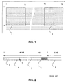
- Figure 1 represents luminance macroblocks of size 16 x 16, a first 16 x 16 luminance macroblock 1 and a last 16 x 16 luminance macroblock 2 of one and the same horizontal row, that is to say of a horizontal succession of macroblocks over an image width.
- a row of macroblocks corresponds to a slice, such as defined in the MPEG standard.
- the term row will be more particularly used to define a succession of blocks or of semi-macroblocks over an image width, the term slice being reserved for the macroblocks.
- the semi-macroblocks are stored one after another according to a television type scanning, as indicated hereinafter.
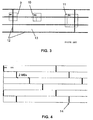
- Figure 2 represents memory pages 4, 5, 6, 8 such as they are successively addressed during the storage of the semi-macroblocks.
- the 16 x 16 macroblocks are stored after separation into two parts, the upper blocks and the lower blocks.
- the upper blocks correspond to one frame and the lower blocks to the next frame, that is to say in image mode the upper blocks are stored one after another in a memory space and the lower blocks one after another in another memory space, each memory space thus corresponding to a frame.
- the upper and lower blocks correspond to one and the same frame, that is to say in frame mode, they are stored one after another, that is to say firstly the upper blocks of a row (of semi-macroblocks) then the lower blocks corresponding to the next row.
- the next frame is stored in another memory space.
- the storage process is described for the frame mode and can be generalized without difficulty to the image mode. It is applied to each of the memory spaces, taken separately, by considering, for each of them, only the semi-macroblocks which are stored therein.
- a page 4 can store, in our example, 8 semi-macroblocks MB referenced 3.
- the storage of the next 8 semi-macroblocks MB is performed in the next page 5 and so on and so forth.
- Semi-macroblock No. 45 which corresponds to the end of the first row is stored in the middle of a page referenced 6, more exactly as 5 th semi-macroblock out of the 8 semi-macroblocks of the page.
- the next semi-macroblock which corresponds to the semi-macroblock at the start of the second row of the frame, is stored at the start of a new page 8 in the memory, the start-of-page storage of a start-of-row semi-macroblock being the simplest solution for handling the addresses.
- Figure 3 shows the drawbacks of such a prior art.
- the memory space is represented schematically as a function of the size of the semi-macroblocks 13 stored.
- the emboldened lines 12 correspond to the boundaries of pages, pages of dimension 8 blocks of 16 x 8 pixels.
- Three overlaid complete pages are represented corresponding to groups of overlaid semi-macroblocks of three successive rows in the frame. Requiring to access image blocks of greater dimension than that of the semi-macroblocks stored, it is necessary to access several pages so as to read an image block.
- access to the block of 17 lines x 9 pixels, referenced 9 requires 4 page changes, access to block 10 of the same dimension, 2 page changes and access to block 11 of dimension 24 lines x 12 pixels, 6 page changes. This calculation takes into account the first page change which has to be performed, simply to access the block.
- the maximum number of page changes for a block of dimension 17 x 9 is 4, the maximum number of page changes for a block of dimension 24 x 12 is 6.
- the memory write/read device must be configured in such a way as to take account of the maximum possible number of page changes. Thus, the greater this number, the greater the access times, even for access to a single page.
- the purpose of the invention is to alleviate the aforesaid drawbacks.
- the subject of the invention is a process for storing digital video data of an image, the image being chopped into first image blocks (h, v) consisting of v lines of h pixels, the set of blocks over an image width constituting a row, the data being stored as successive image blocks in an order corresponding to a television type scanning, in successive pages of a dynamic random access memory, for the reading of second image blocks (H, V) consisting of V lines of H pixels, characterized in that the horizontal shift D I.I+a , in terms of number of first blocks (h, v), of the boundary of a page corresponding to any row I of the image with respect to the boundary of a page corresponding to a row I + a is equal to:
- the process is characterized in that the shift is obtained by leaving memory spaces corresponding to one or more first blocks (h, v) blank in the page storing the last blocks of a row.
- the invention also relates to a process for estimating first motion storming blocks (h, v) of dimensions h, v so as to obtain a reconstructed image in a memory and carrying out a comparison of a block of a current image with second blocks (H, V) of dimension H, V of the stored reconstructed image, characterized in that the first blocks (h, v) are stored in the pages of a memory of SDRAM type according to one of the processes described above.
- the invention also relates to a correlation process performing a storage of first image blocks (h, v) of dimensions h, v so as to obtain a reconstructed image in a memory, a reading of a search window (H, V) of the reconstructed image of dimension H, V so as to carry out a correlation of a block of a current image with an image block lying in the search window, characterized in that the first blocks (h, v) are stored in the pages of a memory of SDRAM type according to one of the processes described above.
- the invention also relates to a process for predicting an image block in a reconstructed image performing a storage of first image blocks (h, v) of dimension h, v so as to obtain a reconstructed image, a prediction on the basis of a motion vector so as to define a second block of dimension (H, V) in the reconstructed image, a reading of this second block (H, V), characterized in that the first blocks (h, v) are stored in the pages of a memory of SDRAM type according to one of the processes described above.
- the maximum number of page changes is limited and consequently the passband is improved.
- the access time to a block of pixels is optimized.
- the minimizing of the time of use of the memory bus, owing to the reduction in the overall transfer time, is particularly advantageous, the passband being an important limitation in the performance of the memory access devices nowadays employed.
- the dimension of the pages is, enlisting the example given earlier, 8 semi-macroblocks of 16 x 8 pixels. From one row of semi-macroblocks to the row beneath, the vertical boundaries 14 of the pages, which boundaries are represented by emboldened lines and correspond to page skips, are shifted by a space equal to 2 semi-macroblocks (or to 2 macroblocks since the width is the same). Thus, the semi-macroblocks of a frame lying beneath the first and second semi-macroblock of a page belong to another page.
- Figure 5 is to be compared with Figure 3 and represents the same image blocks 9, 10, 11 in the memory.
- access to the block of 17 lines x 9 pixels, referenced 9, requires 3 page changes instead of 4, access to block 10 of like dimension, 2 page changes and access to block 11 of dimension 24 lines x 12 pixels, 4 page changes instead of 6.
- the maximum number of page changes for a block of dimension 17 x 9 is 3
- the maximum number of page changes for a block of dimension 24 x 12 is 4.
- the number of page changes can be decreased by two, i.e. a gain of 12 memory clock cycles in our application.
- the shift effected is in fact dependent on the dimensions of the image blocks to be read, relative to those of the stored blocks.
- the stored blocks are of dimension h, v, that is to say consist of v lines of h pixels and are called blocks (h, v).
- the blocks to be read are blocks of dimension H, V, that is to say consist of V lines of H pixels and are called blocks (H, V).
- R M INT [ ( V ⁇ 2 ) / v ] + 2 INT (for INTeger) represents the integer part of the division.
- D be the value of the shift chosen between two successive rows, this value satisfying the inequality: D M ⁇ ( B M ⁇ 1 )
- Figure 6 which is to be compared with Figure 2 represents, on a continuous line, a succession of memory pages 4, 5, 6, 8 such as they are addressed during the storage of the semi-macroblocks.
- a memory area 15 of dimension corresponding to a semi-macroblock is left blank so as to record the first and second semi-macroblocks of the next row at the seventh and eighth site of semi-macroblock in the page.
- the next page 8 records the third semi-macroblock of this next row.
- the semi-macroblock lying, in the frame, above this first semi-macroblock in page 8, has, for its part, been stored as third semi-macroblock in the corresponding page 3 of the upper row.
- a shift of three semi-macroblocks would correspond to no memory space left free, a shift of a single semi-macroblock would correspond to two memory spaces of semi-macroblock dimension.
- the number of semi-macroblocks stored in the first page of the next row, the preceding row commencing with a new page corresponds to this shift, a number of 8 semi-macroblocks corresponding to no shift.
- the storage has been described at the level of the frames of an image. It can be performed at the level of the complete image, for example emanating from sequential scanning.
- the chopping of the image into blocks is then carried out on the basis of the complete image and the image blocks are stored in a single memory space.
- the applications of the present invention relate, for example to access to a predicted block, on the basis of a motion vector, in a reconstructed image, access to the search windows for correlation with a current block during the calculation of the motion estimate.
- the stored blocks can be luminance blocks forming part of the macroblocks defined in the MPEG standard. They may also be chrominance blocks alone or luminance and chrominance blocks together.
- the invention can also be applied to the storage of the blocks reconstructed in an MPEG decoder.
- the predicted blocks to be read from the memory and defined by the motion vectors are generally of greater dimension than the stored blocks, for example when the motion vector is accurate to within half a pixel. These read blocks are thereafter redimensioned by interpolation for the calculation of the current image block.
Landscapes
- Engineering & Computer Science (AREA)
- Multimedia (AREA)
- Signal Processing (AREA)
- Compression Or Coding Systems Of Tv Signals (AREA)
- Television Signal Processing For Recording (AREA)
- Image Input (AREA)
- Memory System (AREA)
Description
- The invention relates to an addressing process for the storage of data in memories of SDRAM type.
- Digital video processing needs to be able to store video images in memory. Two types of memories are commonly used:
- Static Random Access Memories (SRAMs). The areas of these memories are directly accessible from the address bus.
- Dynamic Random Access Memories (DRAMs), or, if they are synchronous, Synchronous Dynamic Random Access Memories (SDRAMs).
- The dynamic memory is split into pages and access to a new page corresponding to a change of page requires an access time referred to as a "time penalty". The memory address is composed of a first part referred to as the page address or "row address" and of a second part referred to as the bin address or "column address". The terms in quotation signs mentioned here are the terms commonly used in technical sheets for DRAM or SDRAM type components.
- Video processing applications, which are becoming increasingly common, need to access image blocks, that it say a set of pixels of an image.
- Such is the case, for example, for digital video data compression according to the MPEG standard, the acronym standing for Motion Picture Expert Group, where the elementary coding size is an image block constituting a macroblock. During motion estimation, a current image macroblock is compared with macroblocks of a reconstructed image which are stored in an SDRAM type memory so as to determine the reconstructed macroblock allowing the best correlation with the current image macroblock.
- In the MPEG standard, the macroblocks are sets consisting of four blocks of 8 x 8 luminance data elements and, for example for the 4: 2: 0 format, of two blocks of 8 x 8 chrominance data elements, emanating from a section of 16 x 16 elements of the luminance component of the image.
- In fact, the motion estimation calculations are performed on the luminance values alone. The relevant blocks are then just the luminance blocks of overall size 16 x 16. These blocks are stored in the form of blocks of 16 pixels x 8 lines, the luminance blocks of overall size 16 x 16 being previously separated into two blocks of 16 pixels x 8 lines. These blocks correspond to a first block of the upper frame and a second block of the lower frame in image mode grouping together two frames or else to a first block grouping together the first 8 lines and a second block grouping together the next 8 lines of the same frame in frame mode. These luminance blocks of 16 pixels x 8 lines are called, hereinafter, luminance semi-macroblocks or simply semi-macroblocks to indicate that they group together 2 luminance blocks of 8 pixels x 8 lines, the term luminance macroblock being used to denote, in the MPEG standard, the 4 luminance blocks.
- It is generally necessary to retrieve, from the memory, image blocks of size greater than these blocks of 16 pixels x 8 lines. The size of the retrieved blocks is in fact defined by the application.
- For example, the calculation of the motion vectors is carried out with a resolution of half a pixel requiring the processing of image blocks having an additional line and a column, that is to say of dimension 17 pixels x 9 lines.
- Another example relates to the search windows in the reconstructed image, in which windows the correlation of the blocks is performed, and which have bigger or smaller dimensions depending on the processes used for the motion estimation. For a process designating, in a first step, a siting of a search window on the basis of a motion vector, it is generally necessary, in a second step, to refine the search so as to perform a local adjustment, this refinement being carried out on a window of small dimension. In one example, these search windows have a dimension of 24 x 12, corresponding to a horizontal excursion of ± 4 and a vertical excursion of ± 2 for blocks of 16 x 8 pixels.
- The access time to an entire block of larger size is not generally optimized, requiring access to several pages of the SDRAM memory so as to read or write the values of pixels constituting this block.
- Figure 1 represents luminance macroblocks of size 16 x 16, a first 16 x 16
luminance macroblock 1 and a last 16 x 16luminance macroblock 2 of one and the same horizontal row, that is to say of a horizontal succession of macroblocks over an image width. In the general case, a row of macroblocks corresponds to a slice, such as defined in the MPEG standard. Hereinafter, the term row will be more particularly used to define a succession of blocks or of semi-macroblocks over an image width, the term slice being reserved for the macroblocks. - Indicated on the abscissa axis are the pixel numbers and indicated on the ordinate axis are the line numbers. 16 video lines over an image width of 720 pixels correspond to 45 macroblocks of 16 pixels (720:16).
- The semi-macroblocks are stored one after another according to a television type scanning, as indicated hereinafter.
- Figure 2 represents
memory pages - If the upper blocks correspond to one frame and the lower blocks to the next frame, that is to say in image mode the upper blocks are stored one after another in a memory space and the lower blocks one after another in another memory space, each memory space thus corresponding to a frame.
- If the upper and lower blocks correspond to one and the same frame, that is to say in frame mode, they are stored one after another, that is to say firstly the upper blocks of a row (of semi-macroblocks) then the lower blocks corresponding to the next row. The next frame is stored in another memory space.
- The storage process is described for the frame mode and can be generalized without difficulty to the image mode. It is applied to each of the memory spaces, taken separately, by considering, for each of them, only the semi-macroblocks which are stored therein.
- A
page 4 can store, in our example, 8 semi-macroblocks MB referenced 3. The storage of the next 8 semi-macroblocks MB is performed in thenext page 5 and so on and so forth. There is therefore, every 8 semi-macroblocks, a page change or skip 7 referred to as a "page miss" in the technical literature. Semi-macroblock No. 45 which corresponds to the end of the first row is stored in the middle of a page referenced 6, more exactly as 5th semi-macroblock out of the 8 semi-macroblocks of the page. - The next semi-macroblock, which corresponds to the semi-macroblock at the start of the second row of the frame, is stored at the start of a
new page 8 in the memory, the start-of-page storage of a start-of-row semi-macroblock being the simplest solution for handling the addresses. - Figure 3 shows the drawbacks of such a prior art. The memory space is represented schematically as a function of the size of the
semi-macroblocks 13 stored. The emboldenedlines 12 correspond to the boundaries of pages, pages ofdimension 8 blocks of 16 x 8 pixels. Three overlaid complete pages are represented corresponding to groups of overlaid semi-macroblocks of three successive rows in the frame. Requiring to access image blocks of greater dimension than that of the semi-macroblocks stored, it is necessary to access several pages so as to read an image block. Thus, access to the block of 17 lines x 9 pixels, referenced 9, requires 4 page changes, access toblock 10 of the same dimension, 2 page changes and access toblock 11 of dimension 24 lines x 12 pixels, 6 page changes. This calculation takes into account the first page change which has to be performed, simply to access the block. - In this configuration, the maximum number of page changes for a block of dimension 17 x 9 is 4, the maximum number of page changes for a block of dimension 24 x 12 is 6.
- The memory write/read device must be configured in such a way as to take account of the maximum possible number of page changes. Thus, the greater this number, the greater the access times, even for access to a single page.
- These page changes or more exactly this maximum possible number of page changes requires a configuration of the system which penalizes access time to the data stored and which therefore reduces the passband of the memory bus, which passband corresponds to the number of pixels which can be accessed in a given duration. A page change requires a certain number of clock cycles, thereby decreasing the access time.
- The article of Winzker M. et Al; "Architecture and Memory Requirements for stand-alone and hierarchical MPEG2 HDTV-Decoders with Synchronous DRAMs", 1995 IEEE International Symposium on Circuits and Systems (ISCAS), Seattle 1995, Vol. 1, 30 April 1995 (1995-04-30), Pages 609-612, and the document EP-A-0 849 953 describe a method to store and address MPEG stantard blocks in a SDRAM memory such that the number of pages in which the data lie, is minimized.
- The purpose of the invention is to alleviate the aforesaid drawbacks.
- To this end, the subject of the invention is a process for storing digital video data of an image, the image being chopped into first image blocks (h, v) consisting of v lines of h pixels, the set of blocks over an image width constituting a row, the data being stored as successive image blocks in an order corresponding to a television type scanning, in successive pages of a dynamic random access memory, for the reading of second image blocks (H, V) consisting of V lines of H pixels, characterized in that the horizontal shift DI.I+a, in terms of number of first blocks (h, v), of the boundary of a page corresponding to any row I of the image with respect to the boundary of a page corresponding to a row I + a is equal to:
- DI,I+a = a D, "a" being a positive integer less than RM = INT [(V - 2) / v] + 2,
- According to a particular mode of implementation, the process is characterized in that the shift is obtained by leaving memory spaces corresponding to one or more first blocks (h, v) blank in the page storing the last blocks of a row.
- The invention also relates to a process for estimating first motion storming blocks (h, v) of dimensions h, v so as to obtain a reconstructed image in a memory and carrying out a comparison of a block of a current image with second blocks (H, V) of dimension H, V of the stored reconstructed image, characterized in that the first blocks (h, v) are stored in the pages of a memory of SDRAM type according to one of the processes described above.
- The invention also relates to a correlation process performing a storage of first image blocks (h, v) of dimensions h, v so as to obtain a reconstructed image in a memory, a reading of a search window (H, V) of the reconstructed image of dimension H, V so as to carry out a correlation of a block of a current image with an image block lying in the search window, characterized in that the first blocks (h, v) are stored in the pages of a memory of SDRAM type according to one of the processes described above.
- The invention also relates to a process for predicting an image block in a reconstructed image performing a storage of first image blocks (h, v) of dimension h, v so as to obtain a reconstructed image, a prediction on the basis of a motion vector so as to define a second block of dimension (H, V) in the reconstructed image, a reading of this second block (H, V), characterized in that the first blocks (h, v) are stored in the pages of a memory of SDRAM type according to one of the processes described above.
- By virtue of the invention, the maximum number of page changes is limited and consequently the passband is improved. The access time to a block of pixels is optimized. The minimizing of the time of use of the memory bus, owing to the reduction in the overall transfer time, is particularly advantageous, the passband being an important limitation in the performance of the memory access devices nowadays employed.
- The characteristics and advantages of the present invention will be better apparent from the following description given by way of example and with reference to the appended figures where:
- Figure 1 represents a first and last macroblock of a slice of macroblocks of an image,
- Figure 2 represents the storage of semi-macroblocks in a memory, according to the prior art,
- Figure 3 represents blocks to be read from a memory configured according to the prior art,
- Figure 4 represents a configuration of the memory space according to the invention,
- Figure 5 represents blocks to be read from a memory configured according to the invention,
- Figure 6 represents the storage of semi-macroblocks in a memory according to the invention.
- The dimension of the pages is, enlisting the example given earlier, 8 semi-macroblocks of 16 x 8 pixels. From one row of semi-macroblocks to the row beneath, the
vertical boundaries 14 of the pages, which boundaries are represented by emboldened lines and correspond to page skips, are shifted by a space equal to 2 semi-macroblocks (or to 2 macroblocks since the width is the same). Thus, the semi-macroblocks of a frame lying beneath the first and second semi-macroblock of a page belong to another page. - Figure 5 is to be compared with Figure 3 and represents the same image blocks 9, 10, 11 in the memory. By virtue of the shifting of the boundaries of the pages, access to the block of 17 lines x 9 pixels, referenced 9, requires 3 page changes instead of 4, access to block 10 of like dimension, 2 page changes and access to block 11 of dimension 24 lines x 12 pixels, 4 page changes instead of 6.
- In this configuration, the maximum number of page changes for a block of dimension 17 x 9 is 3, the maximum number of page changes for a block of dimension 24 x 12 is 4. Thus, by virtue of this configuration, the number of page changes can be decreased by two, i.e. a gain of 12 memory clock cycles in our application.
- The shift effected is in fact dependent on the dimensions of the image blocks to be read, relative to those of the stored blocks.
- The stored blocks are of dimension h, v, that is to say consist of v lines of h pixels and are called blocks (h, v).
- The blocks to be read are blocks of dimension H, V, that is to say consist of V lines of H pixels and are called blocks (H, V).
- The maximum number of rows of blocks, in the memory, over which a block (H, V) of vertical dimension V can be distributed is:

INT (for INTeger) represents the integer part of the division. - The maximum number of blocks, horizontally, over which a block (H, V) of horizontal dimension H can be distributed is:

- The constraints to be observed with regard to the horizontal shift D (in terms of number of blocks stored) of the pages constituting the memory are, between two successive rows of blocks:

- For example, for the (H, V) block referenced 9 or 10, distributed, vertically, at most over two successive rows (RM = 2) and whose dimension H is between 1 and h+1, that is to say a block distributed horizontally over 2 blocks (h, v) at most (BM = 2), the shift D is taken equal to 1.
- When a block (H, V) can be distributed over several rows, the constraint is generalized to the maximum number of rows RM calculated for this block:
- Let D be the value of the shift chosen between two successive rows, this value satisfying the inequality:

- Let a be an integer variable which can range between 1 and RM-1, the constraint can then be written:

with DI.I+a the shift between any row I and a row I + a. - For example, for the block (H, V) referenced 11, distributed, vertically, over at most three successive rows (RM = 3) and whose dimension H is between h+2 and 2h+1, that is to say a block distributed horizontally over 3 blocks (h, v) at most (BM = 3), the shift DI.I+1 is equal to 2 and the shift DI.I+2 is equal to 4.
- To effect such a shift, unused areas are created in the memory space. Figure 6, which is to be compared with Figure 2 represents, on a continuous line, a succession of
memory pages memory area 15 of dimension corresponding to a semi-macroblock is left blank so as to record the first and second semi-macroblocks of the next row at the seventh and eighth site of semi-macroblock in the page. Thus, thenext page 8 records the third semi-macroblock of this next row. The semi-macroblock lying, in the frame, above this first semi-macroblock inpage 8, has, for its part, been stored as third semi-macroblock in the correspondingpage 3 of the upper row. - A shift of three semi-macroblocks would correspond to no memory space left free, a shift of a single semi-macroblock would correspond to two memory spaces of semi-macroblock dimension.
- In general, the number of semi-macroblocks stored in the first page of the next row, the preceding row commencing with a new page, corresponds to this shift, a number of 8 semi-macroblocks corresponding to no shift.
- The description has been given on the basis of the stored semi-macroblocks. This is of course an exemplary embodiment, and the semi-macroblocks may be replaced by any type of image blocks, of any dimension, without the process departing from the field of the invention.
- The storage has been described at the level of the frames of an image. It can be performed at the level of the complete image, for example emanating from sequential scanning. The chopping of the image into blocks is then carried out on the basis of the complete image and the image blocks are stored in a single memory space.
- The applications of the present invention relate, for example to access to a predicted block, on the basis of a motion vector, in a reconstructed image, access to the search windows for correlation with a current block during the calculation of the motion estimate.
- The stored blocks can be luminance blocks forming part of the macroblocks defined in the MPEG standard. They may also be chrominance blocks alone or luminance and chrominance blocks together.
- The invention can also be applied to the storage of the blocks reconstructed in an MPEG decoder. The predicted blocks to be read from the memory and defined by the motion vectors are generally of greater dimension than the stored blocks, for example when the motion vector is accurate to within half a pixel. These read blocks are thereafter redimensioned by interpolation for the calculation of the current image block.
the value D, which corresponds to the shift between two successive rows being chosen such that:

Claims (7)
- Process for storing digital video data of an image, the image being chopped into first image blocks (h, v) (1, 2) consisting of v lines of h pixels, the set of blocks over an image width constituting a row, the data being stored as successive image blocks (3, 13) in an order corresponding to a television type scanning, in successive pages (4, 5, 6, 8) of a dynamic random access memory, for the reading of second image blocks (H, V) (9, 10, 11) consisting of V lines of H pixels, characterized in that, when considering the position of the blocks in the image and of the pages containing them, the horizontal shift DI.I+a, in terms of number of first blocks (h, v), of the boundary of a page corresponding to a row I of the image with respect to the boundary of a page corresponding to a row I + a is equal to:DI.I+a = a D, "a" being a positive integer less than RM = INT [(V - 2) / v] + 2,(INT corresponding to the integer part of the division)
the value D, which corresponds to the shift between two successive rows being chosen such that
- Process according to Claim 1 characterized in that the shift is obtained by leaving memory spaces (15) corresponding to one or more first blocks (h, v) blank in the page storing the last blocks of a row (6).
- Process according to Claim 1 or 2, characterized in that the first blocks (h, v) are part of the macroblocks defined in the MPEG standard.
- Process according to one of the preceding claims, characterized in that the image is an even or odd frame.
- Process for estimating motion storing first blocks (h, v) of dimensions h, v so as to obtain a reconstructed image in a memory and carrying out a comparison of a block of a current image with second blocks (H, V) of dimension H, V of the stored reconstructed image, characterized in that the first blocks (h, v) are stored in the pages of a memory of SDRAM type according to the process of Claim 1 or 2.
- Correlation process performing a storage of first image blocks (h, v) of dimensions h, v so as to obtain a reconstructed image in a memory, a reading of a search window (H, V) of the reconstructed image of dimension H, V so as to carry out a correlation of a block of a current image with an image block lying in the search window, characterized in that the first blocks (h, v) are stored in the pages of a memory of SDRAM type according to the process of Claim 1 or 2.
- Process for predicting an image block in a reconstructed image performing a storage of first image blocks (h, v) of dimension h, v so as to obtain a reconstructed image, a prediction on the basis of a motion vector so as to define a second block of dimension (H, V) in the reconstructed image, a reading of this block (H, V), characterized in that the blocks (h, v) are stored in the pages of a memory of SDRAM type according to the process of claim 1 or 2.
Applications Claiming Priority (2)
| Application Number | Priority Date | Filing Date | Title |
|---|---|---|---|
| FR9816221A FR2787669B1 (en) | 1998-12-22 | 1998-12-22 | ADDRESSING METHOD FOR STORING IMAGE BLOCKS |
| FR9816221 | 1998-12-22 |
Publications (2)
| Publication Number | Publication Date |
|---|---|
| EP1014716A1 EP1014716A1 (en) | 2000-06-28 |
| EP1014716B1 true EP1014716B1 (en) | 2006-04-26 |
Family
ID=9534309
Family Applications (1)
| Application Number | Title | Priority Date | Filing Date |
|---|---|---|---|
| EP99403116A Expired - Lifetime EP1014716B1 (en) | 1998-12-22 | 1999-12-10 | Addressing process for the storage of image blocks |
Country Status (7)
| Country | Link |
|---|---|
| US (1) | US6631164B1 (en) |
| EP (1) | EP1014716B1 (en) |
| JP (1) | JP4435918B2 (en) |
| CN (1) | CN1154048C (en) |
| DE (1) | DE69931017T2 (en) |
| ES (1) | ES2262297T3 (en) |
| FR (1) | FR2787669B1 (en) |
Families Citing this family (5)
| Publication number | Priority date | Publication date | Assignee | Title |
|---|---|---|---|---|
| US7471298B1 (en) * | 2000-06-26 | 2008-12-30 | S3 Graphics Co., Ltd. | Fetching pixel data with reduced memory bandwidth requirement |
| CN100403276C (en) * | 2002-08-26 | 2008-07-16 | 联发科技股份有限公司 | Memory access method |
| US20080158601A1 (en) * | 2006-12-29 | 2008-07-03 | Steven Tu | Image memory tiling |
| US9286696B2 (en) * | 2013-04-08 | 2016-03-15 | Broadcom Corporation | Compression within a set of images |
| CN117499664B (en) * | 2023-12-29 | 2024-03-19 | 南京博润类脑智能技术有限公司 | Image data embedding and extracting method and device based on bit substitution |
Family Cites Families (11)
| Publication number | Priority date | Publication date | Assignee | Title |
|---|---|---|---|---|
| GB2283876B (en) * | 1993-11-09 | 1998-06-24 | Matsushita Electric Industrial Co Ltd | Encoding and decoding code sequences and frames |
| TW245871B (en) * | 1994-08-15 | 1995-04-21 | Gen Instrument Corp | Method and apparatus for efficient addressing of dram in a video decompression processor |
| DE4441295A1 (en) * | 1994-11-21 | 1996-05-23 | Sican Gmbh | Method and circuit arrangement for addressing components of digital image data organized in blocks in a memory with page addressing |
| US5774206A (en) * | 1995-05-10 | 1998-06-30 | Cagent Technologies, Inc. | Process for controlling an MPEG decoder |
| US5872577A (en) * | 1996-02-28 | 1999-02-16 | U.S. Philips Corporation | Device for decoding signals of the MPEG-type |
| US5912676A (en) * | 1996-06-14 | 1999-06-15 | Lsi Logic Corporation | MPEG decoder frame memory interface which is reconfigurable for different frame store architectures |
| US6005624A (en) * | 1996-12-20 | 1999-12-21 | Lsi Logic Corporation | System and method for performing motion compensation using a skewed tile storage format for improved efficiency |
| JPH10191236A (en) * | 1996-12-25 | 1998-07-21 | Nec Corp | Image processor and image data memory arranging method |
| US5883679A (en) * | 1997-02-20 | 1999-03-16 | C-Cube Microsystems, Inc. | Scanning scheme for images stored in dynamic random access memory |
| US6088047A (en) * | 1997-12-30 | 2000-07-11 | Sony Corporation | Motion compensated digital video decoding with buffered picture storage memory map |
| US6104416A (en) * | 1997-11-18 | 2000-08-15 | Stmicroelectronics, Inc. | Tiling in picture memory mapping to minimize memory bandwidth in compression and decompression of data sequences |
-
1998
- 1998-12-22 FR FR9816221A patent/FR2787669B1/en not_active Expired - Fee Related
-
1999
- 1999-12-10 EP EP99403116A patent/EP1014716B1/en not_active Expired - Lifetime
- 1999-12-10 ES ES99403116T patent/ES2262297T3/en not_active Expired - Lifetime
- 1999-12-10 DE DE69931017T patent/DE69931017T2/en not_active Expired - Lifetime
- 1999-12-17 CN CNB991263723A patent/CN1154048C/en not_active Expired - Lifetime
- 1999-12-21 US US09/469,117 patent/US6631164B1/en not_active Expired - Lifetime
- 1999-12-21 JP JP36330699A patent/JP4435918B2/en not_active Expired - Lifetime
Also Published As
| Publication number | Publication date |
|---|---|
| JP4435918B2 (en) | 2010-03-24 |
| FR2787669A1 (en) | 2000-06-23 |
| DE69931017T2 (en) | 2006-09-14 |
| CN1154048C (en) | 2004-06-16 |
| ES2262297T3 (en) | 2006-11-16 |
| CN1258044A (en) | 2000-06-28 |
| FR2787669B1 (en) | 2001-03-02 |
| EP1014716A1 (en) | 2000-06-28 |
| DE69931017D1 (en) | 2006-06-01 |
| JP2000236506A (en) | 2000-08-29 |
| US6631164B1 (en) | 2003-10-07 |
Similar Documents
| Publication | Publication Date | Title |
|---|---|---|
| KR100371834B1 (en) | Pixel interpolation filters and pixel interpolation methods for video extension processors | |
| US6088391A (en) | Method and apparatus for segmenting memory to reduce the memory required for bidirectionally predictive-coded frames | |
| US6104416A (en) | Tiling in picture memory mapping to minimize memory bandwidth in compression and decompression of data sequences | |
| US6130963A (en) | Memory efficient decoding of video frame chroma | |
| EP0543197A2 (en) | Multiple serial access memory for use in feedback systems such as motion compensated television | |
| EP1689195A2 (en) | Picture memory mapping to minimize memory bandwidth in compression and decompression of image sequences | |
| US6081298A (en) | MPEG decoder with reduced memory capacity | |
| US5699459A (en) | Image compression device and a method of image compression | |
| US6266104B1 (en) | Method for controlling memory of HDTV video decoder | |
| US5946037A (en) | Method and apparatus for reordering frames in MPEG coder/decoder | |
| US6631164B1 (en) | Addressing process for the storage of image blocks | |
| JP3120010B2 (en) | Image decoding method and image decoding device | |
| EP0825781B1 (en) | Image processor | |
| US5467135A (en) | Apparatus and method for moving picture coding | |
| EP0714211A2 (en) | Method and circuit for addressing components of blockwise organised digital picture data in a page addressed memory | |
| KR0144440B1 (en) | Integrated memory circuit for picture processing | |
| JPH07298264A (en) | Image data processing method, storage device used for the method and processing unit of image data | |
| US20020071060A1 (en) | Video processor using shared memory space | |
| US5638310A (en) | Pixel matrix filter | |
| US20050083337A1 (en) | Method of storing data-elements | |
| US7050494B1 (en) | Frame display method and apparatus using single field data | |
| US5946036A (en) | Image decoding using read/write memory control based on display region setting | |
| JP3405079B2 (en) | Memory allocation method | |
| KR960011738B1 (en) | Adrs generator in frame & field structure | |
| EP1331604A1 (en) | Method and device for memory access of block encoders/decoders |
Legal Events
| Date | Code | Title | Description |
|---|---|---|---|
| PUAI | Public reference made under article 153(3) epc to a published international application that has entered the european phase |
Free format text: ORIGINAL CODE: 0009012 |
|
| AK | Designated contracting states |
Kind code of ref document: A1 Designated state(s): DE ES FR GB IT |
|
| AX | Request for extension of the european patent |
Free format text: AL;LT;LV;MK;RO;SI |
|
| 17P | Request for examination filed |
Effective date: 20001123 |
|
| AKX | Designation fees paid |
Free format text: DE ES FR GB IT |
|
| GRAP | Despatch of communication of intention to grant a patent |
Free format text: ORIGINAL CODE: EPIDOSNIGR1 |
|
| GRAS | Grant fee paid |
Free format text: ORIGINAL CODE: EPIDOSNIGR3 |
|
| GRAA | (expected) grant |
Free format text: ORIGINAL CODE: 0009210 |
|
| AK | Designated contracting states |
Kind code of ref document: B1 Designated state(s): DE ES FR GB IT |
|
| REG | Reference to a national code |
Ref country code: GB Ref legal event code: FG4D |
|
| REF | Corresponds to: |
Ref document number: 69931017 Country of ref document: DE Date of ref document: 20060601 Kind code of ref document: P |
|
| REG | Reference to a national code |
Ref country code: ES Ref legal event code: FG2A Ref document number: 2262297 Country of ref document: ES Kind code of ref document: T3 |
|
| ET | Fr: translation filed | ||
| PLBE | No opposition filed within time limit |
Free format text: ORIGINAL CODE: 0009261 |
|
| STAA | Information on the status of an ep patent application or granted ep patent |
Free format text: STATUS: NO OPPOSITION FILED WITHIN TIME LIMIT |
|
| 26N | No opposition filed |
Effective date: 20070129 |
|
| REG | Reference to a national code |
Ref country code: FR Ref legal event code: PLFP Year of fee payment: 17 |
|
| REG | Reference to a national code |
Ref country code: FR Ref legal event code: PLFP Year of fee payment: 18 |
|
| REG | Reference to a national code |
Ref country code: DE Ref legal event code: R082 Ref document number: 69931017 Country of ref document: DE Representative=s name: DEHNS, DE Ref country code: DE Ref legal event code: R082 Ref document number: 69931017 Country of ref document: DE Representative=s name: HOFSTETTER, SCHURACK & PARTNER PATENT- UND REC, DE |
|
| REG | Reference to a national code |
Ref country code: FR Ref legal event code: PLFP Year of fee payment: 19 |
|
| REG | Reference to a national code |
Ref country code: FR Ref legal event code: TP Owner name: THOMSON LICENSING DTV, FR Effective date: 20180827 |
|
| REG | Reference to a national code |
Ref country code: FR Ref legal event code: CJ Effective date: 20180912 Ref country code: FR Ref legal event code: CD Owner name: THOMSON LICENSING DTV, FR Effective date: 20180912 Ref country code: FR Ref legal event code: CA Effective date: 20180912 |
|
| REG | Reference to a national code |
Ref country code: GB Ref legal event code: 732E Free format text: REGISTERED BETWEEN 20180927 AND 20181005 |
|
| REG | Reference to a national code |
Ref country code: FR Ref legal event code: TP Owner name: THOMSON LICENSING DTV, FR Effective date: 20180920 |
|
| PGFP | Annual fee paid to national office [announced via postgrant information from national office to epo] |
Ref country code: DE Payment date: 20181126 Year of fee payment: 20 |
|
| PGFP | Annual fee paid to national office [announced via postgrant information from national office to epo] |
Ref country code: FR Payment date: 20181127 Year of fee payment: 20 Ref country code: IT Payment date: 20181122 Year of fee payment: 20 Ref country code: GB Payment date: 20181127 Year of fee payment: 20 |
|
| REG | Reference to a national code |
Ref country code: DE Ref legal event code: R082 Ref document number: 69931017 Country of ref document: DE Representative=s name: DEHNS, DE Ref country code: DE Ref legal event code: R081 Ref document number: 69931017 Country of ref document: DE Owner name: INTERDIGITAL MADISON PATENT HOLDINGS, FR Free format text: FORMER OWNER: THOMSON MULTIMEDIA, BOULOGNE BILLANCOURT, FR |
|
| REG | Reference to a national code |
Ref country code: ES Ref legal event code: PC2A Owner name: INTERDIGITAL MADISON PATENT HOLDINGS Effective date: 20190308 |
|
| PGFP | Annual fee paid to national office [announced via postgrant information from national office to epo] |
Ref country code: ES Payment date: 20190102 Year of fee payment: 20 |
|
| REG | Reference to a national code |
Ref country code: DE Ref legal event code: R071 Ref document number: 69931017 Country of ref document: DE |
|
| REG | Reference to a national code |
Ref country code: GB Ref legal event code: PE20 Expiry date: 20191209 |
|
| PG25 | Lapsed in a contracting state [announced via postgrant information from national office to epo] |
Ref country code: GB Free format text: LAPSE BECAUSE OF EXPIRATION OF PROTECTION Effective date: 20191209 |
|
| REG | Reference to a national code |
Ref country code: ES Ref legal event code: FD2A Effective date: 20200721 |
|
| PG25 | Lapsed in a contracting state [announced via postgrant information from national office to epo] |
Ref country code: ES Free format text: LAPSE BECAUSE OF EXPIRATION OF PROTECTION Effective date: 20191211 |