EP1014677B1 - An artifact removal technique for skew corrected images - Google Patents
An artifact removal technique for skew corrected images Download PDFInfo
- Publication number
- EP1014677B1 EP1014677B1 EP99203956A EP99203956A EP1014677B1 EP 1014677 B1 EP1014677 B1 EP 1014677B1 EP 99203956 A EP99203956 A EP 99203956A EP 99203956 A EP99203956 A EP 99203956A EP 1014677 B1 EP1014677 B1 EP 1014677B1
- Authority
- EP
- European Patent Office
- Prior art keywords
- image
- captured image
- line
- pixels
- pixel
- Prior art date
- Legal status (The legal status is an assumption and is not a legal conclusion. Google has not performed a legal analysis and makes no representation as to the accuracy of the status listed.)
- Expired - Lifetime
Links
Images


Classifications
-
- H—ELECTRICITY
- H04—ELECTRIC COMMUNICATION TECHNIQUE
- H04N—PICTORIAL COMMUNICATION, e.g. TELEVISION
- H04N1/00—Scanning, transmission or reproduction of documents or the like, e.g. facsimile transmission; Details thereof
- H04N1/40—Picture signal circuits
- H04N1/409—Edge or detail enhancement; Noise or error suppression
- H04N1/4097—Removing errors due external factors, e.g. dust, scratches
Definitions
- the present invention relates to an image processing method and system which removes diagonally disposed artifacts such as lines on skew corrected images produced by scanning an original document, without loss of image information.
- EP-A-0 600 613 deals with separating light text from dark text. There is no indication that the technique would be applicable for removing streak artifacts generated by dust.
- Ishitani Y "Document skew detection based on local region complexity" DOCUMENT ANALYSIS AND RECOGNITION; 1993, shows skew angle detection methods. Ishitani is merely one example of a number of references which show skew angle information.
- An object of the present invention is to provide for an artifact detection and removal system and method for skew corrected images. This object is attained by the method as defined in claim 1.
- a further example useful for understanding the invention is a method including the steps of (1) applying an edge-based adaptive thresholding method twice with different contrast parameter settings to convert a skew corrected image such as a gray scale image into two binary images; (2) generating a bitmap of the difference from the two binary images; (3) projecting and accumulating black pixels in the two dimensional bitmap onto a straight line to form a projection profile; (4) detecting locations of local peaks (i.e., line locations) from the projection profile; (5) acquiring the equations of lines from the skew angle and the location values of the detected local peaks; (6) masking the black pixels whose coordinates are within a certain threshold distance along the equations of lines in the bitmap of the difference; and (7) reversing the pixels from a binary image based on the black pixels along the lines in the thresholded binary image.
- a further example of the system and method of the present invention includes deskewing a captured document image such as a gray scale image; applying an edge-based adaptive thresholding technique with a normal contrast setting to extract every detail of image information; storing the resulting binary image, named as B1; applying the same edge-based adaptive thresholding technique with a low contrast setting which only extracts high contrast details of the image, named as B2; labelling the difference of B1 and B2, and storing the map of the difference, named as D; projecting the black pixels in the two dimensional bitmap (D) onto a one dimensional straight line, where the direction of projection is determined by the document skew angle; accumulating the black pixels to form a projection profile; locating the lines by detecting the local peaks in the projection profile, where the detected lines are represented by a set of equations of lines; masking the black pixels whose coordinates are within a certain threshold distance along the equations of lines in the bitmap (D) and resulting in a bitmap of lines, named as V; reading the binary image (B
- a further example of the present invention relates to an image processing method for processing skew corrected images which comprises the steps of: converting a captured skew corrected image into first and second binary images; generating a map indicative of a difference between the first and second binary images; projecting black pixels in the map onto a line to form a projection profile; and reversing pixels in the first binary images based on the projection profile.
- a further example of the present invention relates to an image processing method for processing skew corrected images which comprises the steps of: converting a captured skew corrected image into first and second binary images; comparing the first and second binary images and generating a map indicative of a difference between the first and second binary images; projecting black pixels in the map onto a line to form a projection profile, wherein a direction of projection of the line is based on an original skew angle of the captured image; detecting peaks in the projection profile which are above a specified threshold and generating a line based on the detected peaks, wherein the detected peaks correspond to artifacts on the captured image; masking black pixels in the map which are adjacent to the generated line; and reversing pixels in the first binary image based on the masked pixels.
- a further example of the present invention relates to an image processing method for processing a skewed captured image.
- the method comprises the steps of: deskewing the captured image; extracting image information from the captured image and storing a resulting image as a first binary image; extracting high contrast details from the captured image and storing a resulting image as a second binary image; comparing the first and second binary images and generating a map indicative of a difference between the first and second binary images; projecting black pixels in the map onto a line to form a projection profile, wherein a direction of projection of the line is based on a skew angle of the skewed captured image; detecting peaks in the projection profile which are above a specified threshold and generating a line based on the detected peaks, wherein the detected peaks correspond to artifacts on the captured image; masking black pixels in the map which are adjacent to the generated line; and reversing pixels in the first binary image based on the masked pixels.
- a further example of the present invention relates to an image capture assembly which comprises: an image capture section which captures an image; an image deskewing section which is adapted to correct a captured image that is skewed so as to provide for a captured skewed corrected image; a conversion section which converts the skewed corrected image into digital image information indicative of the skewed corrected captured image; and a processing section which receives the digital information and changes the skewed corrected captured image into first and second binary images, wherein the processing section generates a map indicative of a difference between the first and second binary images, projects black pixels in the map onto a line which is oriented based on a skew angle of the captured image to form a projection profile, and reverses pixels in said first binary image based on said projection profile.
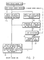
- FIG. 2 a block diagram of a line removal method that performs image deskewing such as gray scale image deskewing and thresholding with minimal line artifacts is shown in Figure 2.
- image deskewing such as gray scale image deskewing and thresholding with minimal line artifacts
- Figure 2 a block diagram of a line removal method that performs image deskewing such as gray scale image deskewing and thresholding with minimal line artifacts.
- image data such as digital gray scale image data is received as input (step 7) and the method and system operate as follows: (1) Gray scale image deskewing with a known skew angle is applied (step 9); (2) An edge-based image thresholding (ATP) is first applied (step 11a) to convert the gray scale image into a binary image (B1) with normal contrast parameter setting which extracts full details of image information; (3) The edge-based image thresholding is applied again (step 11b) to convert the gray scale image into another binary image (B2) with low contrast parameter setting which only extracts high-contrast objects; (4) The two binary images, B1 and B2, are compared pixel-by-pixel (step 14), identifying a pixel as a "black” pixel if there is a difference and "white” if there is no difference, to generate a bitmap of the difference, named as D, between the two binary images B1 and B2; (5) Line detection in the bitmap D is made (step 15) by firstly projecting the black pixels in the bit
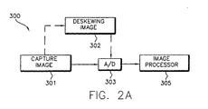
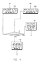
- FIG 2A is a schematic illustration of an image capture assembly 300 which processes images in accordance with the described and illustrated features of the invention.
- Image capture assembly 300 can be a scanner which includes an image capture section 301 in the form of, for example, a charge coupled device that captures an image, an image deskewing or correction section 302, which corrects a captured image that is skewed so as to provide for a skew corrected image, and a conversion section 303 in the form of, for example, an A/D converter which converts the captured image into digital information indicative of the captured image.
- the digital information is sent to a processing section 305 which processes the digital information as described with reference to Figure 2, and as will be further described with reference to Figures 3, 3A, 4, 5 and 6.
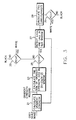
- FIG. 3 is block diagram of an image processing system that performs the edge-based adaptive thresholding.
- the thresholding method receives as input the digital image from a scanner and operator specified input parameters IT (intensity threshold) and GT (gradient threshold) and includes the following steps:
- Sobel gradient operator is applied to the image intensity record to produce a gradient strength record (step 21).
- the Sobel operator works on a 3-by-3 window of pixels, as shown in Figure 3A, to compute the horizontal and vertical intensity gradients, GX(i,j) and GY(i,j) at pixel position (i,j).
- the gradient strength GS(i,j) at pixel position (i,j) is the absolute sum of the horizontal and vertical intensity gradients, GX(i,j) and GY(i,j) respectively.
- , where GS(i,j) Gradient strength record at pixel position (i,j) after gradient operation.
- L(i,j) Image intensity at pixel position (i,j).
- the minimal intensity - Lmin(i,j) and maximal intensity - Lmax(i,j) in a N-by-N window are measured (step 27) from the image intensity record as shown in Fig. 3B and the sum of gradient strength GS(i,j) in a (N-2)-by-(N-2) window, as shown in Figure 3C, is calculated from the gradient strength (step 23 of Figure 3).
- the sum of gradient GS(i,j) is defined as an area gradient.
- the three feature values GS(i,j), Lmin(i,j), Lmax(i,j) are used for classifying the pixel at (i,j) into black or white in the image intensity record.
- the final process is extraction of black pixels (objects).
- the first step of extraction is the detection of pixels near an edge.
- a pixel at (i,j) near an edge is confirmed whenever the area gradient is high and larger than a predetermined value - a gradient threshold (GT) (step 25).
- GT gradient threshold
- the pixel the center pixel of the local window
- the pixel is classified as black (object) when its intensity is smaller than the average of Lmin(i,j) and Lmax(i,j) (steps 29 and 30). That is, it is in the darker side of an edge.
- PA average
- the classification is then made by a simple thresholding. That is, comparing the gray value of the pixel with another predetermined intensity threshold value (IT). If the gray value of a pixel is smaller than IT, the pixel is classified as black; otherwise it is treated as white background (step 33).
- GT gradient threshold
- IT intensity threshold
- the image quality after thresholding by the technique is controlled by the user's selection of the two threshold (GT and IT) setting.
- the GT is set for classifying pixels in vicinity of edges and the IT is then set for classifying pixels in uniform regions.
- a low GT setting tends to extract edge pixels of light objects and a low IT setting inclines to classify pixels of a gray uniform region into white background.
- the algorithm acts just like a fixed thresholding with threshold setting at IT. Since under this situation GT is always larger than the area gradient, the pixel classification of the image as shown in Fig. 3 is solely determined by comparing IT with the intensity at the pixel of interest.
- the technique can also produce an outline image by simply setting the IT to zero in which all pixels classify as white except the edge pixels where area gradients are larger than GT.
- Figure 4 is a block diagram of generating the map of image difference between the two thresholded images B1 and B2. As shown in Figure 4, a bitmap value b1(i,j) which is either 1 (black) or 0 (white) at location (i,j) of the image B1 is read (step 40a), and a bitmap value b2(i,j) at the corresponding location (i,j) of the image B2 is also read (step 40b).
- step 41 If the value b1(i,j) is different from the value b2(i,j) (step 41), that is one is black and the other is white, then the value d(i,j) at location (i,j) of a new map D is marked as 1 (black pixel) (step 42), otherwise, it is marked as 0 (white pixel) (step 43).
- the process above is applied through every pixel location (i,j) in the images B1 and B2, and produces an image map D which indicates the difference of B1 and B2. The process indicates that only the low contrast or light objects are extracted and exhibited in the map of the difference.
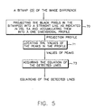
- Figure 5 is a block diagram of a pattern or artifact detection at a given orientation which will be described with respect to detecting lines but is applicable for detecting lines, dashes, dots, etc. and any combination thereof.
- the detection of lines is made by projecting the black pixels in the bitmap (D) into a straight line pointing at a given orientation as indicated in Figure 5A (step 70), and accumulating them into a one dimensional projection profile P(R), where R is the projected line orientation at angle A.
- the projection profile is the frequency distribution of black pixels in a one dimensional diagonal plane. It permits one to easily locate the lines by detecting the peaks (step 71) in the one-dimensional frequency distribution.
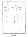
- the two detected lines 100a, 100b are drawn in Figure 5D. Two narrow gray stripes (101) of regions along the lines in Figure 5D are set to mask the unwanted black line pixels in the bitmap (D) in Figure 5B.
- the resulting line bitmap 100a', 100b' is shown in Figure 5E.
- Figure 6 is a block diagram of a pattern or artifact removal process which will be described with respect to removing a line but is applicable for removing lines, dashes, dots, etc., and any combination thereof.
- the bitmap value b1(i,j) at location (i,j) in the image B1 is read, and the bitmap value v(i,j) at the corresponding location (i,j) in the bitmap V is also read (step 80). If the value v(i,j) is marked as "1" (step 82), in which "1" indicates black and "0" indicates white, then the value b1(i,j) is examined (step 83).
- bitmap B is a copy of bitmap B1 after vertical line removal, where b(i,j) is the value of the bitmap B at location (i,j). The process is applied through every pixel location (i,j) in the images B1 and V, and produces a bitmap B whose lines are removed.
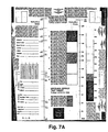
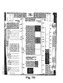
- FIG. 7A An example of a captured, skew gray scale document image using a production scanner is shown in Figure 7A.
- a few light vertical line image artifacts 500 are observed due to pieces of dust blocking light between an illumination light source and the paper document being scanned.
- a 3.9 degree of skew angle in a clockwise direction in the image is detected.
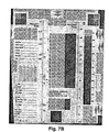
- Figure 7C is the thresholded image obtained by applying the described edge-based thresholding technique with a normal contrast setting to the skew corrected image.
- the pieces of unwanted, light diagonal lines (3.9 degree of skew line) in the gray scale image are also extracted and show up as pieces of broken black line segments 500' in the binary image of Figure 7C.
- the light contrast objects such as the light diagonal lines, light characters and any light objects are ignored in the thresholding process and they are not exhibited in the thresholded image as shown in Figure 7D.
- Figure 7E is the bitmap of the two thresholded images in Figures 7C and 7D.
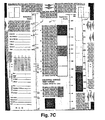
- the projection profile of the bitmap in Figure 7E at a 3.9 degree angle in a counter-clockwise direction is shown in Figure 7F.
- the multiple peaks in the projection profile indicate that there are multiple lines appearing in the bitmap.
- the angle (A) of the projection line as shown in Figure 5A is equal to -3.9 degree in a counter-clockwise direction.
- the locations of the peaks are detected by comparing the value of the count at every location with the given threshold value which is a value of 100 in the example.
- the peaks whose values are larger than the threshold are considered as the detected lines.
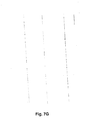
- Figure 7G a line bitmap is obtained and shown in Figure 7G.
- Figure 7H is the final thresholded image in which the line artifacts are removed from the bitmap of Figure 7C.
Description
- The present invention relates to an image processing method and system which removes diagonally disposed artifacts such as lines on skew corrected images produced by scanning an original document, without loss of image information.
- Unexpected vertical black patterns or artifacts such as lines, dots, dashes, etc., have been a common image artifact in binary document images produced by production paper scanners. The vertical black patterns are not part of the original document image, however, the patterns are the result of pieces of dust or dirt blocking light between an illumination light source and the paper documents being scanned. For example, pieces of dust or dirt which come to rest on transparent image guides in an illumination path of the scanner will result in shaded lines upon the document moving through the scanner. When the document is electronically captured by a CCD device, the shaded lines will appear in the digital document image. The shaded vertical lines within a grey scale image will be indistinguishably treated as part of image content. After an adaptive thresholding is applied to the grey scale image, the shaded lines will show up as black lines in the binary image.
- When a paper document is scanned by a production scanner, the resulting digital image is often skewed. The causes of a skewed image are either that the document is not fed properly, or the application of uneven paper carrying forces in a scanning system while transporting a paper document. The skew of a document image produces an unpleasant effect on viewing an image, hence an image skew correction is becoming a desired feature in a document scanning system.
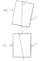
- If the phenomenon of vertical line artifacts occur in a skew image or
document 1 as shown in Figure 1A, avertical line artifact 3 will turn into adiagonal line artifact 5 in the skew corrected image or document 1' as shown in Figure 1B. - Other references have attempted to deal with these problems and may have relevance to the present application. EP-A-0 600 613 deals with separating light text from dark text. There is no indication that the technique would be applicable for removing streak artifacts generated by dust.
- Another reference may also be relevant. Ishitani Y: "Document skew detection based on local region complexity" DOCUMENT ANALYSIS AND RECOGNITION; 1993, shows skew angle detection methods. Ishitani is merely one example of a number of references which show skew angle information.
- An object of the present invention is to provide for an artifact detection and removal system and method for skew corrected images. This object is attained by the method as defined in
claim 1. - A further example useful for understanding the invention is a method including the steps of (1) applying an edge-based adaptive thresholding method twice with different contrast parameter settings to convert a skew corrected image such as a gray scale image into two binary images; (2) generating a bitmap of the difference from the two binary images; (3) projecting and accumulating black pixels in the two dimensional bitmap onto a straight line to form a projection profile; (4) detecting locations of local peaks (i.e., line locations) from the projection profile; (5) acquiring the equations of lines from the skew angle and the location values of the detected local peaks; (6) masking the black pixels whose coordinates are within a certain threshold distance along the equations of lines in the bitmap of the difference; and (7) reversing the pixels from a binary image based on the black pixels along the lines in the thresholded binary image.
- A further example of the system and method of the present invention includes deskewing a captured document image such as a gray scale image; applying an edge-based adaptive thresholding technique with a normal contrast setting to extract every detail of image information; storing the resulting binary image, named as B1; applying the same edge-based adaptive thresholding technique with a low contrast setting which only extracts high contrast details of the image, named as B2; labelling the difference of B1 and B2, and storing the map of the difference, named as D; projecting the black pixels in the two dimensional bitmap (D) onto a one dimensional straight line, where the direction of projection is determined by the document skew angle; accumulating the black pixels to form a projection profile; locating the lines by detecting the local peaks in the projection profile, where the detected lines are represented by a set of equations of lines; masking the black pixels whose coordinates are within a certain threshold distance along the equations of lines in the bitmap (D) and resulting in a bitmap of lines, named as V; reading the binary image (B1) and the map of the lines (V); and reversing the pixels in the binary image B1 at the corresponding black pixel locations in V.
- A further example of the present invention relates to an image processing method for processing skew corrected images which comprises the steps of: converting a captured skew corrected image into first and second binary images; generating a map indicative of a difference between the first and second binary images; projecting black pixels in the map onto a line to form a projection profile; and reversing pixels in the first binary images based on the projection profile.
- A further example of the present invention relates to an image processing method for processing skew corrected images which comprises the steps of: converting a captured skew corrected image into first and second binary images; comparing the first and second binary images and generating a map indicative of a difference between the first and second binary images; projecting black pixels in the map onto a line to form a projection profile, wherein a direction of projection of the line is based on an original skew angle of the captured image; detecting peaks in the projection profile which are above a specified threshold and generating a line based on the detected peaks, wherein the detected peaks correspond to artifacts on the captured image; masking black pixels in the map which are adjacent to the generated line; and reversing pixels in the first binary image based on the masked pixels.
- A further example of the present invention relates to an image processing method for processing a skewed captured image. The method comprises the steps of: deskewing the captured image; extracting image information from the captured image and storing a resulting image as a first binary image; extracting high contrast details from the captured image and storing a resulting image as a second binary image; comparing the first and second binary images and generating a map indicative of a difference between the first and second binary images; projecting black pixels in the map onto a line to form a projection profile, wherein a direction of projection of the line is based on a skew angle of the skewed captured image; detecting peaks in the projection profile which are above a specified threshold and generating a line based on the detected peaks, wherein the detected peaks correspond to artifacts on the captured image; masking black pixels in the map which are adjacent to the generated line; and reversing pixels in the first binary image based on the masked pixels.
- A further example of the present invention relates to an image capture assembly which comprises: an image capture section which captures an image; an image deskewing section which is adapted to correct a captured image that is skewed so as to provide for a captured skewed corrected image; a conversion section which converts the skewed corrected image into digital image information indicative of the skewed corrected captured image; and a processing section which receives the digital information and changes the skewed corrected captured image into first and second binary images, wherein the processing section generates a map indicative of a difference between the first and second binary images, projects black pixels in the map onto a line which is oriented based on a skew angle of the captured image to form a projection profile, and reverses pixels in said first binary image based on said projection profile.
-
- Figure 1A is a graphical example of a vertical line artifact due to pieces of dust in a skewed document;
- Figure 1B is a graphical example of a diagonal line artifact in a skew corrected document;
- Figure 2 is a flowchart of the steps of an image processing system for converting a skew corrected gray scale image into a binary image with minimal image artifacts;
- Figure 2A is a graphical representation of an image capture assembly in accordance with the present invention;
- Figure 3 is a flowchart outlining the steps of an edge-based adaptive thresholding processing (ATP);
- Figure 3A depicts a 3-by-3 matrix of pixel location definition used in determining gradient strength for current pixel(i,j);
- Figure 3B depicts a graphical representation of an N-by-N neighborhood of pixels centered about a current pixel(i,j) in an image intensity record;
- Figure 3C depicts a graphical representation of an (N-2)-by-(N-2) neighborhood of pixels centered about pixel position(i,j) in an image intensity gradient record;
- Figure 4 is a flowchart of generating a bitmap of the difference between two binary images;
- Figure 5 is a flowchart of line detection;
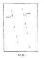
- Figure 5A is a graphical description of acquiring projection profile from a bitmap of the difference between two binary images;
- Figure 5B is an example of a bitmap of the difference (D);
- Figure 5C shows the two detected peaks (R1 and R2) in the acquired projection profile of the bitmap (D) in Figure 5B;
- Figure 5D shows the locations of the two detected lines in the bitmap;
- Figure 5E shows the unwanted line pixels to be deleted from the bitmap (B1);
- Figure 6 is a flowchart of removing the black lines in a thresholded image;
- Figure 7A is a real example of a scanned, skewed document image with 3.9 degree skew angle;
- Figure 7B is the resulting document image of skew correction for the image in Figure 7A;
- Figure 7C is the thresholded image (B1) with normal contrast parameter setting;
- Figure 7D is the thresholded image (B2) with low contrast parameter setting;
- Figure 7E is the bitmap of the difference between the binary images B1 and B2 in Figure 7C and Figure 7D, respectively;
- Figure 7F is the projection profile obtained from the bitmap of Figure 7E;
- Figure 7G is the bitmap of the detected diagonal lines; and
- Figure 7H is the final result of the thresholded image (B).
-
- Referring now to the drawings, wherein like reference numerals represent identical or corresponding parts throughout the several views, a block diagram of a line removal method that performs image deskewing such as gray scale image deskewing and thresholding with minimal line artifacts is shown in Figure 2. Although the invention is described with respect to line removal the invention is not limited thereto. The invention is applicable to the removal of lines, dashes, dots, marks, etc., and any combination thereof. In the method of the present invention, image data such as digital gray scale image data is received as input (step 7) and the method and system operate as follows: (1) Gray scale image deskewing with a known skew angle is applied (step 9); (2) An edge-based image thresholding (ATP) is first applied (
step 11a) to convert the gray scale image into a binary image (B1) with normal contrast parameter setting which extracts full details of image information; (3) The edge-based image thresholding is applied again (step 11b) to convert the gray scale image into another binary image (B2) with low contrast parameter setting which only extracts high-contrast objects; (4) The two binary images, B1 and B2, are compared pixel-by-pixel (step 14), identifying a pixel as a "black" pixel if there is a difference and "white" if there is no difference, to generate a bitmap of the difference, named as D, between the two binary images B1 and B2; (5) Line detection in the bitmap D is made (step 15) by firstly projecting the black pixels in the bitmap D onto a straight line whose angle is equal to a negative value of the skew angle in the original image, then detecting the locations of local peaks in the projection profile, such that the number of the detected peaks reflects the number of the detected lines; (6) A bitmap L of the detected lines is generated (step 17) by masking the black pixels in the bitmap D which are adjacent to the detected lines; and (7) A final thresholded image, binary image B, is obtained (step 19) by removing corresponding black pixels and by filling in corresponding white pixels in the thresholded image B1 in the location of the black pixels in the bitmap L. - Figure 2A is a schematic illustration of an
image capture assembly 300 which processes images in accordance with the described and illustrated features of the invention.Image capture assembly 300 can be a scanner which includes animage capture section 301 in the form of, for example, a charge coupled device that captures an image, an image deskewing orcorrection section 302, which corrects a captured image that is skewed so as to provide for a skew corrected image, and aconversion section 303 in the form of, for example, an A/D converter which converts the captured image into digital information indicative of the captured image. The digital information is sent to aprocessing section 305 which processes the digital information as described with reference to Figure 2, and as will be further described with reference to Figures 3, 3A, 4, 5 and 6. - Figure 3 is block diagram of an image processing system that performs the edge-based adaptive thresholding. The thresholding method receives as input the digital image from a scanner and operator specified input parameters IT (intensity threshold) and GT (gradient threshold) and includes the following steps:
- First, Sobel gradient operator is applied to the image intensity record to produce a gradient strength record (step 21). The Sobel operator works on a 3-by-3 window of pixels, as shown in Figure 3A, to compute the horizontal and vertical intensity gradients, GX(i,j) and GY(i,j) at pixel position (i,j). The gradient strength GS(i,j) at pixel position (i,j) is the absolute sum of the horizontal and vertical intensity gradients, GX(i,j) and GY(i,j) respectively. The GX(i,j) and GY(i,j) are defined as follows:
L(i,j) = Image intensity at pixel position (i,j). - Second, the minimal intensity - Lmin(i,j) and maximal intensity - Lmax(i,j) in a N-by-N window are measured (step 27) from the image intensity record as shown in Fig. 3B and the sum of gradient strength GS(i,j) in a (N-2)-by-(N-2) window, as shown in Figure 3C, is calculated from the gradient strength (
step 23 of Figure 3). The sum of gradient GS(i,j) is defined as an area gradient. Next, the three feature values GS(i,j), Lmin(i,j), Lmax(i,j) are used for classifying the pixel at (i,j) into black or white in the image intensity record. The final process is extraction of black pixels (objects). The first step of extraction is the detection of pixels near an edge. A pixel at (i,j) near an edge is confirmed whenever the area gradient is high and larger than a predetermined value - a gradient threshold (GT) (step 25). After a pixel near an edge is found the pixel (the center pixel of the local window) is classified as black (object) when its intensity is smaller than the average of Lmin(i,j) and Lmax(i,j) (steps 29 and 30). That is, it is in the darker side of an edge. On the other hand, if its intensity is larger than the average (PA) of Lmin(i,j) and Lmax(i,j) it is classified into white (background). In case of an area gradient smaller than the gradient threshold (GT), such as a NxN window moving in a flat region, the classification is then made by a simple thresholding. That is, comparing the gray value of the pixel with another predetermined intensity threshold value (IT). If the gray value of a pixel is smaller than IT, the pixel is classified as black; otherwise it is treated as white background (step 33). - The image quality after thresholding by the technique is controlled by the user's selection of the two threshold (GT and IT) setting. The GT is set for classifying pixels in vicinity of edges and the IT is then set for classifying pixels in uniform regions. A low GT setting tends to extract edge pixels of light objects and a low IT setting inclines to classify pixels of a gray uniform region into white background. On the other hand, with a very high GT setting, the algorithm acts just like a fixed thresholding with threshold setting at IT. Since under this situation GT is always larger than the area gradient, the pixel classification of the image as shown in Fig. 3 is solely determined by comparing IT with the intensity at the pixel of interest. The technique can also produce an outline image by simply setting the IT to zero in which all pixels classify as white except the edge pixels where area gradients are larger than GT.
- Figure 4 is a block diagram of generating the map of image difference between the two thresholded images B1 and B2. As shown in Figure 4, a bitmap value b1(i,j) which is either 1 (black) or 0 (white) at location (i,j) of the image B1 is read (step 40a), and a bitmap value b2(i,j) at the corresponding location (i,j) of the image B2 is also read (
step 40b). If the value b1(i,j) is different from the value b2(i,j) (step 41), that is one is black and the other is white, then the value d(i,j) at location (i,j) of a new map D is marked as 1 (black pixel) (step 42),
otherwise, it is marked as 0 (white pixel) (step 43). The process above is applied through every pixel location (i,j) in the images B1 and B2, and produces an image map D which indicates the difference of B1 and B2. The process indicates that only the low contrast or light objects are extracted and exhibited in the map of the difference. - Figure 5 is a block diagram of a pattern or artifact detection at a given orientation which will be described with respect to detecting lines but is applicable for detecting lines, dashes, dots, etc. and any combination thereof. The detection of lines is made by projecting the black pixels in the bitmap (D) into a straight line pointing at a given orientation as indicated in Figure 5A (step 70), and accumulating them into a one dimensional projection profile P(R), where R is the projected line orientation at angle A. The projection profile is the frequency distribution of black pixels in a one dimensional diagonal plane. It permits one to easily locate the lines by detecting the peaks (step 71) in the one-dimensional frequency distribution. Figure 5B is an example of a bitmap (D) with two detected lines or
artifacts 100a,100b. Its projection profile is shown in Figure 5C. Two peaks which are above a specified threshold are detected at R1 and R2. The two detected peaks reflect the two detected lines orartifacts 100a, 100b. Their equations (step 73) are R1 = X1 * cos(A) + Y1 * sin(A) and R2 = X2 * cos(A) + Y2 * sin(A), respectively, where x and y are the cartesian coordinates as defined in Figure 5A. The two detectedlines 100a, 100b are drawn in Figure 5D. Two narrow gray stripes (101) of regions along the lines in Figure 5D are set to mask the unwanted black line pixels in the bitmap (D) in Figure 5B. The resulting line bitmap 100a', 100b' is shown in Figure 5E. - Figure 6 is a block diagram of a pattern or artifact removal process which will be described with respect to removing a line but is applicable for removing lines, dashes, dots, etc., and any combination thereof. In the process, the bitmap value b1(i,j) at location (i,j) in the image B1 is read, and the bitmap value v(i,j) at the corresponding location (i,j) in the bitmap V is also read (step 80). If the value v(i,j) is marked as "1" (step 82), in which "1" indicates black and "0" indicates white, then the value b1(i,j) is examined (step 83). If the value v(i,j) is marked as "o", then b(i,j) is set equal to b1(i,j) (step 85). If the value b1(i,j) is marked as "1" (black pixel) (step 83), then the value b1(i,j) is turned into "0" (white) (step 84). On the other hand, if the value b1(i,j) is marked as "0", then the value b1(i,j) is turned into "1" (black) (step 86). The bitmap B is a copy of bitmap B1 after vertical line removal, where b(i,j) is the value of the bitmap B at location (i,j). The process is applied through every pixel location (i,j) in the images B1 and V, and produces a bitmap B whose lines are removed.
- An example of a captured, skew gray scale document image using a production scanner is shown in Figure 7A. A few light vertical
line image artifacts 500 are observed due to pieces of dust blocking light between an illumination light source and the paper document being scanned. A 3.9 degree of skew angle in a clockwise direction in the image is detected. After gray scale deskewing, it was observed that the original vertical line artifacts exhibit a 3.9 degree of skew in a counter-clockwise direction in the skew corrected image of Figure 7B. Figure 7C is the thresholded image obtained by applying the described edge-based thresholding technique with a normal contrast setting to the skew corrected image. Since the image thresholding with a normal contrast setting attempts to extract every details of image information in the gray scale image, the pieces of unwanted, light diagonal lines (3.9 degree of skew line) in the gray scale image are also extracted and show up as pieces of broken black line segments 500' in the binary image of Figure 7C. In the case of low contrast setting, the light contrast objects such as the light diagonal lines, light characters and any light objects are ignored in the thresholding process and they are not exhibited in the thresholded image as shown in Figure 7D. - Figure 7E is the bitmap of the two thresholded images in Figures 7C and 7D. The projection profile of the bitmap in Figure 7E at a 3.9 degree angle in a counter-clockwise direction is shown in Figure 7F. The multiple peaks in the projection profile indicate that there are multiple lines appearing in the bitmap. Setting the value of threshold at 100, there are four peaks in the projection profile detected at R=505, 930, 1450 and 1690, respectively. For a 3.9 degree skew angle in a clockwise direction, the angle (A) of the projection line as shown in Figure 5A is equal to -3.9 degree in a counter-clockwise direction. The equations of the corresponding four straight lines are acquired as follows:
- The locations of the peaks are detected by comparing the value of the count at every location with the given threshold value which is a value of 100 in the example. The peaks whose values are larger than the threshold are considered as the detected lines. According to the masking process described in the section of Line Detection mentioned above, a line bitmap is obtained and shown in Figure 7G. Figure 7H is the final thresholded image in which the line artifacts are removed from the bitmap of Figure 7C.
Claims (8)
- An image processing method for processing a skewed captured image, the method comprising the steps of:deskewing the skewed captured image;extracting image information from said deskewed captured image and storing a resulting image as a first binary image;extracting high contrast details from said deskewed captured image and storing a resulting image as a second binary image;comparing said first and second binary images and generating a map indicative of a difference between said first and second binary images;projecting black pixels in said map onto a line to form a projection profile, a direction of projection being based on a skew angle of said skewed captured image;detecting peaks in said projection profile which are above a specified threshold and generating a line corresponding to line artifacts on said deskewed captured image based on said detected peaks, the detected peaks corresponding to artifacts on said deskewed captured image;masking black pixels in said map which are adjacent to or on said generated line; andreversing black pixels in said first binary image based on said masked region.
- A method according to claim 1, wherein said first and second threshold settings are
edge-based image threshold settings. - A method according to claim 1, wherein said detected peaks represent linearly disposed artifacts in said deskewed captured image which each have the following equation:
- A method according to claim 1, wherein one of said first and second binary images has a normal contrast parameter, and the other of said first and second binary images has a low contrast parameter.
- A method according to claim 1, wherein said artifact is at least one of a line, dash, or dot.
- A method according to claim 1, wherein said skewed captured image is a gray scale image.
- A method according to claim 1, wherein said comparing step comprises the steps of:comparing said first and second binary images in a pixel by pixel manner; andidentifying a pixel as a black pixel if there is a difference between the compared pixels and a white pixel if there is no difference between the compared pixels to generate said map.
- An image processing method according to claim 1, wherein a direction of projection is based on an original skew angle of said skewed captured image.
Applications Claiming Priority (2)
| Application Number | Priority Date | Filing Date | Title |
|---|---|---|---|
| US09/211,125 US6282326B1 (en) | 1998-12-14 | 1998-12-14 | Artifact removal technique for skew corrected images |
| US211125 | 1998-12-14 |
Publications (3)
| Publication Number | Publication Date |
|---|---|
| EP1014677A2 EP1014677A2 (en) | 2000-06-28 |
| EP1014677A3 EP1014677A3 (en) | 2002-05-15 |
| EP1014677B1 true EP1014677B1 (en) | 2005-07-20 |
Family
ID=22785677
Family Applications (1)
| Application Number | Title | Priority Date | Filing Date |
|---|---|---|---|
| EP99203956A Expired - Lifetime EP1014677B1 (en) | 1998-12-14 | 1999-11-25 | An artifact removal technique for skew corrected images |
Country Status (4)
| Country | Link |
|---|---|
| US (1) | US6282326B1 (en) |
| EP (1) | EP1014677B1 (en) |
| JP (1) | JP4256042B2 (en) |
| DE (1) | DE69926205T2 (en) |
Families Citing this family (31)
| Publication number | Priority date | Publication date | Assignee | Title |
|---|---|---|---|---|
| US6317223B1 (en) * | 1998-12-14 | 2001-11-13 | Eastman Kodak Company | Image processing system for reducing vertically disposed patterns on images produced by scanning |
| US6529641B1 (en) * | 1999-10-29 | 2003-03-04 | Eastman Kodak Company | Method for deskewing a scanned text image |
| US6606421B1 (en) * | 2000-05-25 | 2003-08-12 | Hewlett-Packard Development Company, L.P. | Geometric deformation correction method and system for dot pattern images |
| US7031543B2 (en) * | 2002-01-02 | 2006-04-18 | Xerox Corporation | Grayscale image de-speckle algorithm |
| US6947607B2 (en) * | 2002-01-04 | 2005-09-20 | Warner Bros. Entertainment Inc. | Reduction of differential resolution of separations |
| US7092584B2 (en) | 2002-01-04 | 2006-08-15 | Time Warner Entertainment Company Lp | Registration of separations |
| US6873728B2 (en) * | 2002-01-16 | 2005-03-29 | Eastman Kodak Company | Vertical black line removal implementation |
| US7151859B2 (en) * | 2002-01-16 | 2006-12-19 | Ricoh Company, Ltd | Method and system for correcting direction or orientation of document image |
| US7068855B2 (en) * | 2002-07-16 | 2006-06-27 | Hewlett-Packard Development Company, L.P. | System and method for manipulating a skewed digital image |
| US7142718B2 (en) * | 2002-10-28 | 2006-11-28 | Lee Shih-Jong J | Fast pattern searching |
| US7773270B2 (en) * | 2004-01-07 | 2010-08-10 | Hewlett-Packard Development Company, L.P. | Image scanner feature detection |
| US7483591B2 (en) * | 2004-02-17 | 2009-01-27 | Xerox Corporation | Image transfer apparatus with streak removal system |
| US7593595B2 (en) * | 2004-08-26 | 2009-09-22 | Compulink Management Center, Inc. | Photographic document imaging system |
| US7391930B2 (en) * | 2004-12-17 | 2008-06-24 | Primax Electronics Ltd. | Angle de-skew device and method thereof |
| JP4123267B2 (en) * | 2005-10-31 | 2008-07-23 | コニカミノルタビジネステクノロジーズ株式会社 | Image processing device |
| US7330604B2 (en) * | 2006-03-02 | 2008-02-12 | Compulink Management Center, Inc. | Model-based dewarping method and apparatus |
| US7729559B2 (en) * | 2006-05-22 | 2010-06-01 | Ge Healthcare Bio-Sciences Corp. | System and method for optical section image line removal |
| EP2143041A4 (en) * | 2007-05-01 | 2011-05-25 | Compulink Man Ct Inc | Photo-document segmentation method and system |
| US8249391B2 (en) * | 2007-08-24 | 2012-08-21 | Ancestry.com Operations, Inc. | User interface method for skew correction |
| WO2009137073A1 (en) * | 2008-05-06 | 2009-11-12 | Compulink Management Center, Inc. | Camera-based document imaging |
| US9547799B2 (en) * | 2008-07-17 | 2017-01-17 | Sharp Laboratories Of America, Inc. | Methods and systems for content-boundary detection |
| US8370759B2 (en) | 2008-09-29 | 2013-02-05 | Ancestry.com Operations Inc | Visualizing, creating and editing blending modes methods and systems |
| US20110110604A1 (en) * | 2009-11-10 | 2011-05-12 | Prakash Reddy | Cropping scanned pages to remove artifacts |
| US8873864B2 (en) * | 2009-12-16 | 2014-10-28 | Sharp Laboratories Of America, Inc. | Methods and systems for automatic content-boundary detection |
| US8903173B2 (en) * | 2011-12-21 | 2014-12-02 | Ncr Corporation | Automatic image processing for document de-skewing and cropping |
| US9241128B2 (en) | 2013-02-14 | 2016-01-19 | Warner Bros. Entertainment Inc. | Video conversion technology |
| US20140279323A1 (en) * | 2013-03-15 | 2014-09-18 | Mitek Systems, Inc. | Systems and methods for capturing critical fields from a mobile image of a credit card bill |
| US9235755B2 (en) * | 2013-08-15 | 2016-01-12 | Konica Minolta Laboratory U.S.A., Inc. | Removal of underlines and table lines in document images while preserving intersecting character strokes |
| US9495343B2 (en) * | 2014-09-30 | 2016-11-15 | Konica Minolta Laboratory U.S.A., Inc. | Horizontal and vertical line detection and removal for document images |
| JP7030425B2 (en) * | 2017-05-22 | 2022-03-07 | キヤノン株式会社 | Image processing device, image processing method, program |
| CN113852730B (en) * | 2021-09-28 | 2023-12-01 | 科大讯飞股份有限公司 | Inclination angle determining method and related equipment thereof |
Family Cites Families (9)
| Publication number | Priority date | Publication date | Assignee | Title |
|---|---|---|---|---|
| JPS6478381A (en) * | 1987-09-21 | 1989-03-23 | Toshiba Corp | Picture processing method |
| US5054098A (en) * | 1990-05-21 | 1991-10-01 | Eastman Kodak Company | Method of detecting the skew angle of a printed business form |
| US5214470A (en) * | 1992-04-09 | 1993-05-25 | Xerox Corporation | Method and apparatus for compensating for dirt or etched areas on a document platen |
| US5594815A (en) * | 1992-10-19 | 1997-01-14 | Fast; Bruce B. | OCR image preprocessing method for image enhancement of scanned documents |
| GB9224952D0 (en) * | 1992-11-28 | 1993-01-20 | Ibm | Improvements in image processing |
| US5583659A (en) * | 1994-11-10 | 1996-12-10 | Eastman Kodak Company | Multi-windowing technique for thresholding an image using local image properties |
| US5949901A (en) * | 1996-03-21 | 1999-09-07 | Nichani; Sanjay | Semiconductor device image inspection utilizing image subtraction and threshold imaging |
| DE19613342A1 (en) * | 1996-04-03 | 1997-10-09 | Philips Patentverwaltung | Automatic image evaluation process |
| US6035072A (en) * | 1997-12-08 | 2000-03-07 | Read; Robert Lee | Mapping defects or dirt dynamically affecting an image acquisition device |
-
1998
- 1998-12-14 US US09/211,125 patent/US6282326B1/en not_active Expired - Lifetime
-
1999
- 1999-11-09 JP JP31878599A patent/JP4256042B2/en not_active Expired - Lifetime
- 1999-11-25 EP EP99203956A patent/EP1014677B1/en not_active Expired - Lifetime
- 1999-11-25 DE DE69926205T patent/DE69926205T2/en not_active Expired - Lifetime
Also Published As
| Publication number | Publication date |
|---|---|
| EP1014677A3 (en) | 2002-05-15 |
| JP2000184192A (en) | 2000-06-30 |
| DE69926205D1 (en) | 2005-08-25 |
| JP4256042B2 (en) | 2009-04-22 |
| US6282326B1 (en) | 2001-08-28 |
| DE69926205T2 (en) | 2006-05-24 |
| EP1014677A2 (en) | 2000-06-28 |
Similar Documents
| Publication | Publication Date | Title |
|---|---|---|
| EP1014677B1 (en) | An artifact removal technique for skew corrected images | |
| US6317223B1 (en) | Image processing system for reducing vertically disposed patterns on images produced by scanning | |
| US6160913A (en) | Method and apparatus for digital halftone dots detection and removal in business documents | |
| US7292375B2 (en) | Method and apparatus for color image processing, and a computer product | |
| EP0569962B1 (en) | Method and apparatus for processing a two dimensional digital image | |
| JP4261005B2 (en) | Region-based image binarization system | |
| EP0947947B1 (en) | Robust method for finding registration marker positions | |
| US20060039628A1 (en) | Detecting skew angle in a scanned image | |
| US8331670B2 (en) | Method of detection document alteration by comparing characters using shape features of characters | |
| JP2009535899A (en) | Generation of bi-tonal images from scanned color images. | |
| JP2003219184A (en) | Imaging process for forming clear and legible binary image | |
| US20060165292A1 (en) | Noise resistant edge detection | |
| US6993190B1 (en) | System and method for detecting text edges in digital document images | |
| US6381035B1 (en) | Edge compaction in antialiased images | |
| EP0505729B1 (en) | Image binarization system | |
| JP2005184787A (en) | Image processing method and device | |
| EP1184808A2 (en) | Method for detection of skew angle and border of document images in a production scanning environment | |
| RU2520407C1 (en) | Method and system of text improvement at digital copying of printed documents | |
| EP0869662B1 (en) | Image binarization system | |
| EP0569982B1 (en) | Method and apparatus for processing images with symbols with dense edges | |
| JPH09120456A (en) | Method and device for image processing, and copying machine, printer, and scanner using same | |
| KR19990011500A (en) | Local binarization method of the imaging system | |
| JP3877535B2 (en) | Color image processing method, color image processing apparatus, color image processing program, and recording medium | |
| JP2937603B2 (en) | Binary discrimination method of image data in image data reading device | |
| US20060239454A1 (en) | Image forming method and an apparatus capable of adjusting brightness of text information and image information of printing data |
Legal Events
| Date | Code | Title | Description |
|---|---|---|---|
| PUAI | Public reference made under article 153(3) epc to a published international application that has entered the european phase |
Free format text: ORIGINAL CODE: 0009012 |
|
| AK | Designated contracting states |
Kind code of ref document: A2 Designated state(s): AT BE CH CY DE DK ES FI FR GB GR IE IT LI LU MC NL PT SE |
|
| AX | Request for extension of the european patent |
Free format text: AL;LT;LV;MK;RO;SI |
|
| PUAL | Search report despatched |
Free format text: ORIGINAL CODE: 0009013 |
|
| AK | Designated contracting states |
Kind code of ref document: A3 Designated state(s): AT BE CH CY DE DK ES FI FR GB GR IE IT LI LU MC NL PT SE |
|
| AX | Request for extension of the european patent |
Free format text: AL;LT;LV;MK;RO;SI |
|
| RIC1 | Information provided on ipc code assigned before grant |
Free format text: 7H 04N 1/00 A, 7H 04N 1/387 B, 7H 04N 1/409 B, 7G 06T 5/50 B |
|
| 17P | Request for examination filed |
Effective date: 20021021 |
|
| AKX | Designation fees paid |
Designated state(s): DE FR GB |
|
| 17Q | First examination report despatched |
Effective date: 20031117 |
|
| GRAP | Despatch of communication of intention to grant a patent |
Free format text: ORIGINAL CODE: EPIDOSNIGR1 |
|
| GRAS | Grant fee paid |
Free format text: ORIGINAL CODE: EPIDOSNIGR3 |
|
| GRAA | (expected) grant |
Free format text: ORIGINAL CODE: 0009210 |
|
| AK | Designated contracting states |
Kind code of ref document: B1 Designated state(s): DE FR GB |
|
| REG | Reference to a national code |
Ref country code: GB Ref legal event code: FG4D |
|
| REF | Corresponds to: |
Ref document number: 69926205 Country of ref document: DE Date of ref document: 20050825 Kind code of ref document: P |
|
| ET | Fr: translation filed | ||
| PLBE | No opposition filed within time limit |
Free format text: ORIGINAL CODE: 0009261 |
|
| STAA | Information on the status of an ep patent application or granted ep patent |
Free format text: STATUS: NO OPPOSITION FILED WITHIN TIME LIMIT |
|
| 26N | No opposition filed |
Effective date: 20060421 |
|
| PGFP | Annual fee paid to national office [announced via postgrant information from national office to epo] |
Ref country code: FR Payment date: 20121113 Year of fee payment: 14 |
|
| PGFP | Annual fee paid to national office [announced via postgrant information from national office to epo] |
Ref country code: GB Payment date: 20121025 Year of fee payment: 14 |
|
| GBPC | Gb: european patent ceased through non-payment of renewal fee |
Effective date: 20131125 |
|
| REG | Reference to a national code |
Ref country code: FR Ref legal event code: ST Effective date: 20140731 |
|
| REG | Reference to a national code |
Ref country code: DE Ref legal event code: R082 Ref document number: 69926205 Country of ref document: DE Representative=s name: WAGNER & GEYER PARTNERSCHAFT PATENT- UND RECHT, DE |
|
| PG25 | Lapsed in a contracting state [announced via postgrant information from national office to epo] |
Ref country code: FR Free format text: LAPSE BECAUSE OF NON-PAYMENT OF DUE FEES Effective date: 20131202 Ref country code: GB Free format text: LAPSE BECAUSE OF NON-PAYMENT OF DUE FEES Effective date: 20131125 |
|
| REG | Reference to a national code |
Ref country code: DE Ref legal event code: R082 Ref document number: 69926205 Country of ref document: DE Representative=s name: WAGNER & GEYER PARTNERSCHAFT MBB PATENT- UND R, DE Effective date: 20141028 Ref country code: DE Ref legal event code: R082 Ref document number: 69926205 Country of ref document: DE Representative=s name: WAGNER & GEYER PARTNERSCHAFT PATENT- UND RECHT, DE Effective date: 20141028 Ref country code: DE Ref legal event code: R081 Ref document number: 69926205 Country of ref document: DE Owner name: KODAK ALARIS INC., ROCHESTER, US Free format text: FORMER OWNER: EASTMAN KODAK CO., ROCHESTER, N.Y., US Effective date: 20141028 |
|
| PGFP | Annual fee paid to national office [announced via postgrant information from national office to epo] |
Ref country code: DE Payment date: 20181015 Year of fee payment: 20 |
|
| REG | Reference to a national code |
Ref country code: DE Ref legal event code: R071 Ref document number: 69926205 Country of ref document: DE |