EP1014224B1 - Image forming apparatus and controlling method thereof - Google Patents
Image forming apparatus and controlling method thereof Download PDFInfo
- Publication number
- EP1014224B1 EP1014224B1 EP99125578A EP99125578A EP1014224B1 EP 1014224 B1 EP1014224 B1 EP 1014224B1 EP 99125578 A EP99125578 A EP 99125578A EP 99125578 A EP99125578 A EP 99125578A EP 1014224 B1 EP1014224 B1 EP 1014224B1
- Authority
- EP
- European Patent Office
- Prior art keywords
- sheet
- face
- conveying
- discharge portion
- sheet discharge
- Prior art date
- Legal status (The legal status is an assumption and is not a legal conclusion. Google has not performed a legal analysis and makes no representation as to the accuracy of the status listed.)
- Expired - Lifetime
Links
- 238000000034 method Methods 0.000 title claims description 16
- 230000001939 inductive effect Effects 0.000 claims description 30
- 238000005259 measurement Methods 0.000 claims description 21
- 238000012545 processing Methods 0.000 description 9
- 238000012546 transfer Methods 0.000 description 3
- 238000010276 construction Methods 0.000 description 2
- 238000010586 diagram Methods 0.000 description 2
- 238000010438 heat treatment Methods 0.000 description 2
- 230000001419 dependent effect Effects 0.000 description 1
- 238000011161 development Methods 0.000 description 1
- 230000018109 developmental process Effects 0.000 description 1
- 230000006698 induction Effects 0.000 description 1
- 238000012544 monitoring process Methods 0.000 description 1
- 230000001360 synchronised effect Effects 0.000 description 1
Images


Classifications
-
- G—PHYSICS
- G03—PHOTOGRAPHY; CINEMATOGRAPHY; ANALOGOUS TECHNIQUES USING WAVES OTHER THAN OPTICAL WAVES; ELECTROGRAPHY; HOLOGRAPHY
- G03G—ELECTROGRAPHY; ELECTROPHOTOGRAPHY; MAGNETOGRAPHY
- G03G15/00—Apparatus for electrographic processes using a charge pattern
- G03G15/65—Apparatus which relate to the handling of copy material
- G03G15/6552—Means for discharging uncollated sheet copy material, e.g. discharging rollers, exit trays
-
- B—PERFORMING OPERATIONS; TRANSPORTING
- B65—CONVEYING; PACKING; STORING; HANDLING THIN OR FILAMENTARY MATERIAL
- B65H—HANDLING THIN OR FILAMENTARY MATERIAL, e.g. SHEETS, WEBS, CABLES
- B65H29/00—Delivering or advancing articles from machines; Advancing articles to or into piles
- B65H29/52—Stationary guides or smoothers
-
- B—PERFORMING OPERATIONS; TRANSPORTING
- B65—CONVEYING; PACKING; STORING; HANDLING THIN OR FILAMENTARY MATERIAL
- B65H—HANDLING THIN OR FILAMENTARY MATERIAL, e.g. SHEETS, WEBS, CABLES
- B65H85/00—Recirculating articles, i.e. feeding each article to, and delivering it from, the same machine work-station more than once
-
- G—PHYSICS
- G03—PHOTOGRAPHY; CINEMATOGRAPHY; ANALOGOUS TECHNIQUES USING WAVES OTHER THAN OPTICAL WAVES; ELECTROGRAPHY; HOLOGRAPHY
- G03G—ELECTROGRAPHY; ELECTROPHOTOGRAPHY; MAGNETOGRAPHY
- G03G15/00—Apparatus for electrographic processes using a charge pattern
- G03G15/22—Apparatus for electrographic processes using a charge pattern involving the combination of more than one step according to groups G03G13/02 - G03G13/20
- G03G15/23—Apparatus for electrographic processes using a charge pattern involving the combination of more than one step according to groups G03G13/02 - G03G13/20 specially adapted for copying both sides of an original or for copying on both sides of a recording or image-receiving material
- G03G15/231—Arrangements for copying on both sides of a recording or image-receiving material
Definitions
- the present invention relates to an image forming apparatus such as a laser printer capable of forming images on a front surface and a back surface of a sheet and a controlling method of this image forming apparatus, and particularly relates to an image forming apparatus having a both-face conveying portion for reversing surfaces of a sheet on one surface of which an image is formed and conveying the sheet to an image forming portion.
- a both-face conveying portion having a both-face conveying path for conveying the sheet to the image forming portion by reversing the surfaces of the sheet is optionally mounted to a relatively large-sized device operated at high speed and high in cost, and images are recorded to both surfaces of the sheet.
- a tendency to the requirement of a function for recording images to both surfaces of the sheet is increasing to save resources, etc. even in a laser printer, etc. made compact and operated at low speed and low in cost.
- the conventional image recorder having such a both-face conveying portion has a one-face mode for forming an image on one surface of the sheet and a both-face mode for reversing by the both-face conveying portion the surfaces of the sheet on one surface of which an image is formed and conveying this reversed sheet to the image forming portion and forming an image on a back surface of the sheet.
- a face-up tray is openably and closably arranged in an apparatus body to face-up-discharge the sheet on one surface of which the image is formed.
- the sheet is stored in a face-up state by opening this face-up tray.
- the face-up tray When the sheet is stored in a face-down state in the one-face mode, the face-up tray is closed to form a sheet discharge path for conveying the sheet to a face-down storing portion arranged on an upper face of the apparatus body. Further, this face-up tray is closed in the both-face mode to form the sheet discharge path for conveying the sheet forming images on both surfaces thereof to the face-down storing portion and a conveying path to the both-face conveying portion.
- the present invention has been made in view of such a situation, and therefore has an object to provide an image recorder (image forming apparatus) able to be constructed such that no image recorder is jammed with a sheet even when a face-up tray is opened during a both-face mode.
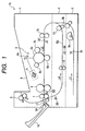
- Fig. 1 is a view for explaining the schematic construction of a laser beam printer as one example of an image forming apparatus in accordance with an embodiment of the present invention.
- reference character 1A designates a laser beam printer.
- This laser beam printer 1A has a one-face mode for forming an image on one surface of a sheet of paper and a both-face mode for forming an image on a back surface of the sheet of paper on one surface of which an image is formed.
- Reference characters 1, 2, and 3 respectively designate a main body of a laser beam printer (hereinafter called a main body), a both-face conveying portion having a both-face conveying path R2 and detachably mountable to the main body 1, and a sheet cassette (paper cassette) for storing the unexposed sheet of paper.
- the sheet stored to this sheet cassette 3 is fed in a direction indicated by reference character L1 by operating a cassette sheet pickup roller 3a and a pair of conveying rollers 3b. Thereafter, the sheet is conveyed in a direction indicated by reference character L2 by operating a pair of conveying rollers 3c.
- Reference numeral 4 designates a laser scanner unit.
- the laser scanner unit 4 raster-scans a laser beam on the basis of image data from a host computer, etc. described later and forms an electrostatic latent image by a reflecting mirror 4a on a photosensitive drum 5a charged by a charger 5b in advance.
- the electrostatic latent image formed on the photosensitive drum 5a is toner-developed by a developing device 5c and is then transferred in a transfer portion 5d to the sheet conveyed by the pair of conveying rollers 3c.
- thermal fixing device 6 is constructed by an unillustrated heating member, a thermistor for detecting a temperature of this heating member, etc. such that heat and pressure are applied to the sheet terminated with respect to the transfer process and the toner image is fixed to the sheet.
- Reference numeral 7 designates a pair of sheet discharge rollers constructing conveying means.
- the sheet passing through the thermal fixing device 6 is discharged by this pair of sheet discharge rollers 7 to a face-up tray 10 as a second sheet discharge portion, or a face-down sheet discharge portion 9 as a first sheet discharge portion arranged on an upper face of the main body 1.
- the face-up tray 10 is arranged in the main body 1 so as to be openable and closable. When the sheet is discharged in a face-up state, this face-up tray 10 is opened as shown in Fig. 1.
- the face-up tray 10 is closed as shown by a broken line of Fig. 2.
- a sheet discharge path R1 for conveying the sheet to the face-down sheet discharge portion 9 is secured by closing the face-up tray 10 in this way.
- the sheet can be discharged to the face-down sheet discharge portion 9 in the one-face mode and the both-face mode by operating a pair of face-down sheet discharge rollers 8 as forward and reverse rotatable conveying means in the direction indicated by arrows a.
- the face-up tray 10 is closed and the pair of face-down sheet discharge rollers 8 is forwardly rotated for a predetermined time period so that the sheet is conveyed toward the face-down sheet discharge portion 9. Thereafter, the pair of face-down sheet discharge rollers 8 is reversely rotated so that the sheet is conveyed toward the both-face conveying portion 2.
- the sheet conveyed toward the both-face conveying portion 2 in this way is conveyed to the both-face conveying path R2 by a reversed sheet inducing roller 11 as reversed sheet inducing means. Further, the sheet conveyed to this both-face conveying path R2 is conveyed by a pair of reversed sheet conveying rollers 12 in a direction indicated by reference character L4. Thereafter, the sheet is stopped before a pair of reversed sheet re-feeding rollers 13 shown in Fig. 1 and is on standby until this sheet is re-fed as a sheet for a second surface (a back surface) of both-face printing.
- reference character S6 designates a re-feeding sensor arranged in the both-face conveying portion 2.
- this re-feeding sensor S6 detects that the sheet conveyed to the both-face conveying path R2 reaches a predetermined re-feeding position, the re-feeding sensor S6 outputs a detecting signal to an engine controller portion 14 as control means shown in Fig. 3 and described later.
- the engine controller portion 14 stops rotations of the pair of reversed sheet conveying rollers 12 on the basis of the detecting signal from this re-feeding sensor S6 and sets the sheet to be on standby in the predetermined re-feeding position. thereafter, the engine controller portion 14 operates the pair of reversed sheet re-feeding rollers 13 in predetermined timing.
- the sheet on standby in the both-face conveying path R2 is re-fed to the image forming portion 5 through the pair of conveying rollers 3c. Thereafter, this sheet is printed on the second surface (back surface) in both-face printing in a conveying path similar to that in the printing operation from the sheet cassette 3 described before. Thereafter, the sheet is discharged to the face-down sheet discharge portion 9.
- reference characters S3 and S4 respectively designate a sheet discharge sensor as sheet detecting means for detecting that the sheet passes through the thermal fixing device 6, and a face-up tray open and close detecting sensor as second sheet discharge portion open and close detecting means for detecting that the face-up tray 10 is opened and closed.
- this face-up tray open and close detecting sensor S4 detects that the face-up tray 10 is closed, the engine controller portion 14 performs face-down sheet discharge and sheet conveyance to the both-face conveying path R2 as already mentioned above.
- reference characters S1 and S2 respectively designate a sheet sensor for detecting existence and nonexistence of the sheet in the sheet cassette 3, and a sheet feeding sensor for detecting a leading end and a trailing end of the sheet conveyed by operating the pair of conveying rollers 3c.
- the engine controller portion 14 judges image write timing on the basis of a detecting signal from this sheet feeding sensor S2.
- Reference character S5 designates a reversed sheet induction detecting sensor for detecting timing of the sheet conveyed to the both-face conveying path R2 and the leading and trailing ends of the sheet.
- Fig. 3 is a block diagram of a printer controller portion for controlling the above series of printing operations.
- This printer controller portion is mainly constructed by the engine controller portion 14 and an image controller portion 15.
- the image controller portion 15 receives encoded image information (code data) from a host computer 17, etc. through an unillustrated external interface. Thereafter, the image controller portion 15 converts the code data into video data of a dot image and sends out printing commands to the engine controller portion 14 through an unillustrated video interface. Further, the image controller portion 15 sequentially sends out the video data to the engine controller portion 14 in synchronization with main scanning and subscanning synchronous signals from the engine controller portion 14.
- code data encoded image information
- the image controller portion 15 converts the code data into video data of a dot image and sends out printing commands to the engine controller portion 14 through an unillustrated video interface. Further, the image controller portion 15 sequentially sends out the video data to the engine controller portion 14 in synchronization with main scanning and subscanning synchronous signals from the engine controller portion 14.
- the engine controller portion 14 also generally controls the operation of a printer engine such as the laser scanner unit 4, the thermal fixing device 6 by monitoring the operations of respective rollers such as the sheet discharge roller 7, the pair of face-down sheet discharge rollers 8, the pair of conveying rollers, etc. and inputs from the face-up tray open and close detecting sensor S4 and the other sensors.
- the engine controller portion 14 is also arranged to print the video data from the image controller portion 15 to the sheet.
- this engine controller portion 14 has a timer 20 as time measuring means as shown in Fig. 3.
- the engine controller portion 14 operates the timer 20 on the basis of this detecting signal and judges by time measurement information from this timer 20 that the sheet passing through the sheet discharge sensor S3 reaches the pair of face-down sheet discharge rollers 8.
- the pair of face-down sheet discharge rollers 8 When the engine controller portion 14 judges by the time measurement information from this timer 20 that the sheet has reached the pair of face-down sheet discharge rollers 8, the pair of face-down sheet discharge rollers 8 is forwardly rotated for a predetermined time period and is then stopped in the both-face mode. Thereafter, the pair of face-down sheet discharge rollers 8 is reversely rotated in a predetermined timing so that the sheet is fed to the both-face conveying portion 2.
- a detecting signal for detecting the opening of the face-up tray 10 is inputted from the face-up tray open and close detecting sensor S4 to the engine controller portion 14.
- this detecting signal is inputted to the engine controller portion 14, the engine controller portion 14 performs the following controls according to opening timing of the face-up tray 10, i.e., the time measurement information from the timer 20.
- the engine controller portion 14 judges in accordance with the time measurement information from the timer 20 that the face-up tray 10 is opened before the sheet reaches the pair of face-down sheet discharge rollers 8, the engine controller portion 14 continues the operation of the sheet discharge roller 7 for a predetermined time period.
- the sheet can be discharged to the face-up tray 10 even when the face-up tray 10 is opened and no sheet discharge path R1 can be formed.
- the engine controller portion 14 judges that the face-up tray 10 is opened after the pair of face-down sheet discharge rollers 8 nips the sheet having reached the pair of face-down sheet discharge rollers 8 and is forwardly rotated and before the pair of face-down sheet discharge rollers 8 is stopped for reverse rotation, the engine controller portion 14 continues the forward rotation of the pair of face-down sheet discharge rollers 8 for a predetermined time period.
- the sheet can be discharged to the face-down sheet discharge portion 9 without jamming even when the face-up tray 10 is opened.
- the engine controller portion 14 judges that the face-up tray 10 is opened in a state in which the pair of face-down sheet discharge rollers 8 nips the sheet and is stopped, the engine controller portion 14 restarts the forward rotation of the pair of face-down sheet discharge rollers 8 for a predetermined time period.
- the sheet can be discharged to the face-down sheet discharge portion 9 without jamming even when the face-up tray 10 is opened.
- the engine controller portion 14 judges that the face-up tray 10 is opened after the pair of face-down sheet discharge rollers 8 is reversely rotated and before the sheet reaches the pair of reversed sheet inducing rollers 11, the engine controller portion 14 again rotates the pair of face-down sheet discharge rollers 8 forwardly.
- the sheet can be discharged to the face-down sheet discharge portion 9 without jamming even when the face-up tray 10 is opened.
- the sheet can be normally conveyed without having any influence on the conveyance of the sheet to the both-face conveying path R2 even when the face-up tray 10 is opened. Therefore, the printing operation in the normal both-face mode is continued even when the opening of the face-up tray 10 is detected.
- the timer 20 When the sheet discharge sensor S3 detects passage of the sheet (YES of F101) after the printing operation is performed on the front surface of the sheet in the both-face mode, the timer 20 is operated and a measurement of time is started after the sheet has passed through the sheet discharge sensor S3 (F102). It is then judged by time measurement information from this timer 20 whether or not the sheet reaches the pair of face-down sheet discharge rollers 8 (F103). When it is judged that the sheet has reached the pair of face-down sheet discharge rollers 8 (YES of F103), thereafter the pair of face-down sheet discharge rollers 8 is forwardly rotated for a predetermined time period as already described and is then reversely rotated and the printing operation in the normal both-face mode is continued (F107).
- the sheet is conveyed by continuously operating the sheet discharge roller 7 for a predetermined time period required to discharge the sheet to the face-up tray 10, and is discharged to the face-up tray 10. After the sheet is completely discharged, the measurement of time using the timer 20 is stopped (F105). Further, thereafter, the both-face mode is discontinued.
- the face-up tray 10 is opened in the both-face mode before the sheet completed with respect to the printing operation on the first surface reaches the pair of face-down sheet discharge rollers 8, the sheet is discharged to the face-up tray 10 as it is so that jamming of the sheet can be prevented. Further, after the sheet is completely discharged, the printing operation on the next page can be received by ending the both-face mode operation of this sheet.
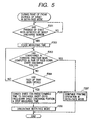
- a processing operation when the face-up tray 10 is opened after the completion of the printing operation on the first surface and before a conveyance completing time of the sheet fed toward the face-down sheet discharge portion in the pair of face-down sheet discharge rollers 8, i.e., after the pair of face-down sheet discharge rollers 8 begins to be forwardly rotated and before the pair of face-down sheet discharge rollers 8 is stopped for reverse rotation will be explained in conjunction with a flowchart shown in Fig. 5.
- the timer 20 is operated and the measurement of a time from the passage of the sheet in the sheet discharge sensor S3 is started (F202). It is then judged by time measurement information from this timer 20 whether or not the sheet reaches the pair of face-down sheet discharge rollers 8 and conveyance of the sheet in a predetermined forward direction (toward the face-down sheet discharge portion) is completed by a subsequent forward rotation of the pair of face-down sheet discharge rollers 8 for a predetermined time period (F203).
- the pair of face-down sheet discharge rollers 8 is then reversely rotated for a predetermined time period as already mentioned before so that the sheet is fed toward the both-face conveying portion 2 and the printing operation in the normal both-face mode is continued (F207).
- the face-up tray 10 when the face-up tray 10 is opened before the pair of face-down sheet discharge rollers 8 conveys the sheet in the predetermined forward direction (NO of F203) and this opening is detected by a detecting signal from the face-up tray open and close detecting sensor S4 (YES of F204), the sheet is conveyed for a predetermined time period by continuing the forward rotation of the pair of face-down sheet discharge rollers 8 for a predetermined time period required to discharge the sheet to the face-down sheet discharge portion 9, and is discharged to the face-down sheet discharge portion 9. After the sheet is completely discharged, the measurement of time using the timer 20 is stopped (F205). Further, thereafter, the both-face mode is discontinued (F206).
- the face-up tray 10 is opened in the both-face mode before a conveyance completing time of the sheet completed with respect to the printing operation on the first surface in the forward direction using the pair of face-down sheet discharge rollers 8, the sheet is discharged to the face-down sheet discharge portion 9 as it is so that jamming of the sheet can be prevented. Further, after the sheet is completely discharged, the printing operation on the next page can be received by ending the both-face mode operation of this sheet.
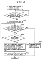
- the conveyance of the sheet in a predetermined forward direction is terminated by the forward rotation of the pair of face-down sheet discharge rollers 8 for a predetermined time period. Further, it is judged whether subsequent stop and wait of the pair of face-down sheet discharge rollers 8 is completed or not (F303). When it is judged that the stop and wait is completed (YES of F303), the pair of face-down sheet discharge rollers 8 is then reversely rotated for a predetermined time period as already described so that the sheet is fed toward the both-face conveying portion 2 and the printing operation in the normal both-face mode is continued (F307).
- the face-up tray 10 when the face-up tray 10 is opened in the stopping state of the pair of face-down sheet discharge rollers 8 in the both-face mode, the sheet is discharged to the face-down sheet discharge portion 9 so that jamming of the sheet can be prevented. Further, after the sheet is completely discharged, the printing operation on the next page can be received by ending the both-face mode operation of this sheet.
- the timer 20 is operated and the measurement of time from the passage of the sheet in the sheet discharge sensor S3 is started (F402).
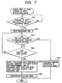
- the reverse rotation of the pair of face-down sheet discharge rollers 8 is started by time measurement information from this timer 20. Further, it is judged whether or not the sheet reaches the pair of reversed sheet inducing rollers 11 by this reverse rotation of the pair of face-down sheet discharge rollers 8 (F403). When it is judged that the sheet has reached the pair of reversed sheet inducing rollers 11 (YES of F403), the printing operation in the normal both-face mode is then continued (F407).
- the face-up tray 10 is opened in the both-face mode before the sheet completed with respect to the printing operation on the first surface reaches the pair of reversed sheet inducing rollers 11, the sheet is discharged to the face-down sheet discharge portion 9 by re-rotating the pair of face-down sheet discharge rollers 8 forwardly so that jamming of the sheet can be prevented. Further, after the sheet is completely discharged, the printing operation on the next page can be received by ending the both-face mode operation of this sheet.
- the sheet When the sheet reaches the pair of reversed sheet inducing rollers 11 and begins to be conveyed by the pair of reversed sheet inducing rollers 11, the sheet can be normally conveyed without having any influence on the conveyance of the sheet to the both-face conveying path R1 even when the face-up tray 10 is opened. Therefore, the printing operation in the normal both-face mode is continued.
- a sheet on one surface of which an image is formed can be conveyed to the first or second sheet discharge portion or the both-face conveying portion by controlling a rotating direction of a both-face conveying means on the basis of time measurement information from time measuring means so that jamming of the sheet can be prevented.
- uselessness of the sheet can be omitted and the printing operation on the next page can be performed so that a user friendly image forming apparatus can be provided.
Landscapes
- Physics & Mathematics (AREA)
- General Physics & Mathematics (AREA)
- Engineering & Computer Science (AREA)
- Mechanical Engineering (AREA)
- Separation, Sorting, Adjustment, Or Bending Of Sheets To Be Conveyed (AREA)
- Conveyance By Endless Belt Conveyors (AREA)
- Counters In Electrophotography And Two-Sided Copying (AREA)
- Paper Feeding For Electrophotography (AREA)
- Control Or Security For Electrophotography (AREA)
Description
- The present invention relates to an image forming apparatus such as a laser printer capable of forming images on a front surface and a back surface of a sheet and a controlling method of this image forming apparatus, and particularly relates to an image forming apparatus having a both-face conveying portion for reversing surfaces of a sheet on one surface of which an image is formed and conveying the sheet to an image forming portion.
- There is a conventional image forming apparatus in which surfaces of a sheet on one surface of which an image is formed by an image forming portion is reversed and the sheet is again conveyed to the image forming portion and an image is formed on a back surface of the sheet.
- For example, in an image recorder such as a laser printer as one example of the conventional image forming apparatus, a both-face conveying portion having a both-face conveying path for conveying the sheet to the image forming portion by reversing the surfaces of the sheet is optionally mounted to a relatively large-sized device operated at high speed and high in cost, and images are recorded to both surfaces of the sheet. Recently, a tendency to the requirement of a function for recording images to both surfaces of the sheet is increasing to save resources, etc. even in a laser printer, etc. made compact and operated at low speed and low in cost.
- The conventional image recorder having such a both-face conveying portion has a one-face mode for forming an image on one surface of the sheet and a both-face mode for reversing by the both-face conveying portion the surfaces of the sheet on one surface of which an image is formed and conveying this reversed sheet to the image forming portion and forming an image on a back surface of the sheet.
- Further, for example, a face-up tray is openably and closably arranged in an apparatus body to face-up-discharge the sheet on one surface of which the image is formed. In the one-face mode, the sheet is stored in a face-up state by opening this face-up tray.
- When the sheet is stored in a face-down state in the one-face mode, the face-up tray is closed to form a sheet discharge path for conveying the sheet to a face-down storing portion arranged on an upper face of the apparatus body. Further, this face-up tray is closed in the both-face mode to form the sheet discharge path for conveying the sheet forming images on both surfaces thereof to the face-down storing portion and a conveying path to the both-face conveying portion.
- However, when the sheet discharge path is formed by the face-up tray in this way, there is a case in which the sheet on one surface of which the image is formed is not conveyed to the both-face conveying portion but the sheet discharge path is jammed with the sheet when the face-up tray is opened in error particularly in the both-face mode.
- Therefore, the present invention has been made in view of such a situation, and therefore has an object to provide an image recorder (image forming apparatus) able to be constructed such that no image recorder is jammed with a sheet even when a face-up tray is opened during a both-face mode.
- This object is achieved by an image forming apparatus according to claim 1 and a control method of an image forming apparatus according to
claim 11. Advantageous further developments are subject to the dependent claims. -
- Fig. 1 is a view for explaining the schematic construction of a laser beam printer as one example of an image forming apparatus in accordance with an embodiment of the present invention;
- Fig. 2 is an enlarged view of a main portion of the laser beam printer;
- Fig. 3 is a control block diagram of the laser beam printer;
- Fig. 4 is a flowchart for explaining a processing operation when a face-up tray is opened before a sheet in an engine controller portion of the laser beam printer reaches a pair of face-down sheet discharge rollers;
- Fig. 5 is a flowchart for explaining a processing operation when the face-up tray is opened after the pair of face-down sheet discharge rollers of the engine controller portion begins to be forwardly rotated and before the pair of face-down sheet discharge rollers is stopped for reverse rotation;
- Fig. 6 is a flowchart for explaining a processing operation when the face-up tray is opened in a stopping state of the pair of face-down sheet discharge rollers of the engine controller portion; and
- Fig. 7 is a flowchart for explaining a processing operation when the face-up tray is opened during reverse conveyance of the pair of face-down sheet discharge rollers of the engine controller portion.
-
- The embodiments of the present invention will be explained in conjunction with the drawings.
- Fig. 1 is a view for explaining the schematic construction of a laser beam printer as one example of an image forming apparatus in accordance with an embodiment of the present invention.
- In Fig. 1,
reference character 1A designates a laser beam printer. Thislaser beam printer 1A has a one-face mode for forming an image on one surface of a sheet of paper and a both-face mode for forming an image on a back surface of the sheet of paper on one surface of which an image is formed.Reference characters - The sheet stored to this
sheet cassette 3 is fed in a direction indicated by reference character L1 by operating a cassettesheet pickup roller 3a and a pair ofconveying rollers 3b. Thereafter, the sheet is conveyed in a direction indicated by reference character L2 by operating a pair ofconveying rollers 3c. -
Reference numeral 4 designates a laser scanner unit. Thelaser scanner unit 4 raster-scans a laser beam on the basis of image data from a host computer, etc. described later and forms an electrostatic latent image by a reflectingmirror 4a on aphotosensitive drum 5a charged by acharger 5b in advance. The electrostatic latent image formed on thephotosensitive drum 5a is toner-developed by a developingdevice 5c and is then transferred in atransfer portion 5d to the sheet conveyed by the pair ofconveying rollers 3c. - Further, the toner image transferred onto this sheet is fixed to the sheet by a
thermal fixing device 6. Thisthermal fixing device 6 is constructed by an unillustrated heating member, a thermistor for detecting a temperature of this heating member, etc. such that heat and pressure are applied to the sheet terminated with respect to the transfer process and the toner image is fixed to the sheet. - Reference numeral 7 designates a pair of sheet discharge rollers constructing conveying means. The sheet passing through the
thermal fixing device 6 is discharged by this pair of sheet discharge rollers 7 to a face-uptray 10 as a second sheet discharge portion, or a face-downsheet discharge portion 9 as a first sheet discharge portion arranged on an upper face of the main body 1. Here, the face-uptray 10 is arranged in the main body 1 so as to be openable and closable. When the sheet is discharged in a face-up state, this face-up tray 10 is opened as shown in Fig. 1. - In contrast to this, when the sheet is discharged in a face-down state, the face-
up tray 10 is closed as shown by a broken line of Fig. 2. A sheet discharge path R1 for conveying the sheet to the face-downsheet discharge portion 9 is secured by closing the face-uptray 10 in this way. The sheet can be discharged to the face-downsheet discharge portion 9 in the one-face mode and the both-face mode by operating a pair of face-downsheet discharge rollers 8 as forward and reverse rotatable conveying means in the direction indicated by arrows a. - In the both-face mode, the face-
up tray 10 is closed and the pair of face-downsheet discharge rollers 8 is forwardly rotated for a predetermined time period so that the sheet is conveyed toward the face-downsheet discharge portion 9. Thereafter, the pair of face-downsheet discharge rollers 8 is reversely rotated so that the sheet is conveyed toward the both-face conveying portion 2. - The sheet conveyed toward the both-
face conveying portion 2 in this way is conveyed to the both-face conveying path R2 by a reversedsheet inducing roller 11 as reversed sheet inducing means. Further, the sheet conveyed to this both-face conveying path R2 is conveyed by a pair of reversedsheet conveying rollers 12 in a direction indicated by reference character L4. Thereafter, the sheet is stopped before a pair of reversedsheet re-feeding rollers 13 shown in Fig. 1 and is on standby until this sheet is re-fed as a sheet for a second surface (a back surface) of both-face printing. - In Fig. 1, reference character S6 designates a re-feeding sensor arranged in the both-
face conveying portion 2. When this re-feeding sensor S6 detects that the sheet conveyed to the both-face conveying path R2 reaches a predetermined re-feeding position, the re-feeding sensor S6 outputs a detecting signal to anengine controller portion 14 as control means shown in Fig. 3 and described later. - The
engine controller portion 14 stops rotations of the pair of reversedsheet conveying rollers 12 on the basis of the detecting signal from this re-feeding sensor S6 and sets the sheet to be on standby in the predetermined re-feeding position. thereafter, theengine controller portion 14 operates the pair of reversedsheet re-feeding rollers 13 in predetermined timing. Thus, the sheet on standby in the both-face conveying path R2 is re-fed to the image forming portion 5 through the pair ofconveying rollers 3c. Thereafter, this sheet is printed on the second surface (back surface) in both-face printing in a conveying path similar to that in the printing operation from thesheet cassette 3 described before. Thereafter, the sheet is discharged to the face-downsheet discharge portion 9. - In Fig. 1, reference characters S3 and S4 respectively designate a sheet discharge sensor as sheet detecting means for detecting that the sheet passes through the
thermal fixing device 6, and a face-up tray open and close detecting sensor as second sheet discharge portion open and close detecting means for detecting that the face-up tray 10 is opened and closed. When this face-up tray open and close detecting sensor S4 detects that the face-up tray 10 is closed, theengine controller portion 14 performs face-down sheet discharge and sheet conveyance to the both-face conveying path R2 as already mentioned above. - In Fig. 1, reference characters S1 and S2 respectively designate a sheet sensor for detecting existence and nonexistence of the sheet in the
sheet cassette 3, and a sheet feeding sensor for detecting a leading end and a trailing end of the sheet conveyed by operating the pair ofconveying rollers 3c. Theengine controller portion 14 judges image write timing on the basis of a detecting signal from this sheet feeding sensor S2. Reference character S5 designates a reversed sheet induction detecting sensor for detecting timing of the sheet conveyed to the both-face conveying path R2 and the leading and trailing ends of the sheet. - Fig. 3 is a block diagram of a printer controller portion for controlling the above series of printing operations. This printer controller portion is mainly constructed by the
engine controller portion 14 and animage controller portion 15. - Here, the
image controller portion 15 receives encoded image information (code data) from ahost computer 17, etc. through an unillustrated external interface. Thereafter, theimage controller portion 15 converts the code data into video data of a dot image and sends out printing commands to theengine controller portion 14 through an unillustrated video interface. Further, theimage controller portion 15 sequentially sends out the video data to theengine controller portion 14 in synchronization with main scanning and subscanning synchronous signals from theengine controller portion 14. - The
engine controller portion 14 also generally controls the operation of a printer engine such as thelaser scanner unit 4, thethermal fixing device 6 by monitoring the operations of respective rollers such as the sheet discharge roller 7, the pair of face-downsheet discharge rollers 8, the pair of conveying rollers, etc. and inputs from the face-up tray open and close detecting sensor S4 and the other sensors. Theengine controller portion 14 is also arranged to print the video data from theimage controller portion 15 to the sheet. - Further, this
engine controller portion 14 has atimer 20 as time measuring means as shown in Fig. 3. When a detecting signal from the sheet discharge sensor S3 is inputted to theengine controller portion 14, theengine controller portion 14 operates thetimer 20 on the basis of this detecting signal and judges by time measurement information from thistimer 20 that the sheet passing through the sheet discharge sensor S3 reaches the pair of face-downsheet discharge rollers 8. - When the
engine controller portion 14 judges by the time measurement information from thistimer 20 that the sheet has reached the pair of face-downsheet discharge rollers 8, the pair of face-downsheet discharge rollers 8 is forwardly rotated for a predetermined time period and is then stopped in the both-face mode. Thereafter, the pair of face-downsheet discharge rollers 8 is reversely rotated in a predetermined timing so that the sheet is fed to the both-face conveying portion 2. - When the face-up
tray 10 is opened in error in such a both-face mode, a detecting signal for detecting the opening of the face-uptray 10 is inputted from the face-up tray open and close detecting sensor S4 to theengine controller portion 14. When this detecting signal is inputted to theengine controller portion 14, theengine controller portion 14 performs the following controls according to opening timing of the face-uptray 10, i.e., the time measurement information from thetimer 20. - Namely, when the
engine controller portion 14 judges in accordance with the time measurement information from thetimer 20 that the face-uptray 10 is opened before the sheet reaches the pair of face-downsheet discharge rollers 8, theengine controller portion 14 continues the operation of the sheet discharge roller 7 for a predetermined time period. Thus, the sheet can be discharged to the face-uptray 10 even when the face-uptray 10 is opened and no sheet discharge path R1 can be formed. - Further, when the
engine controller portion 14 judges that the face-uptray 10 is opened after the pair of face-downsheet discharge rollers 8 nips the sheet having reached the pair of face-downsheet discharge rollers 8 and is forwardly rotated and before the pair of face-downsheet discharge rollers 8 is stopped for reverse rotation, theengine controller portion 14 continues the forward rotation of the pair of face-downsheet discharge rollers 8 for a predetermined time period. Thus, the sheet can be discharged to the face-downsheet discharge portion 9 without jamming even when the face-uptray 10 is opened. - When the
engine controller portion 14 judges that the face-uptray 10 is opened in a state in which the pair of face-downsheet discharge rollers 8 nips the sheet and is stopped, theengine controller portion 14 restarts the forward rotation of the pair of face-downsheet discharge rollers 8 for a predetermined time period. Thus, the sheet can be discharged to the face-downsheet discharge portion 9 without jamming even when the face-uptray 10 is opened. - When the
engine controller portion 14 judges that the face-uptray 10 is opened after the pair of face-downsheet discharge rollers 8 is reversely rotated and before the sheet reaches the pair of reversedsheet inducing rollers 11, theengine controller portion 14 again rotates the pair of face-downsheet discharge rollers 8 forwardly. Thus, the sheet can be discharged to the face-downsheet discharge portion 9 without jamming even when the face-uptray 10 is opened. - When the
engine controller portion 14 judges that the face-uptray 10 is opened after the sheet reaches the pair of reversedsheet inducing rollers 11, the sheet can be normally conveyed without having any influence on the conveyance of the sheet to the both-face conveying path R2 even when the face-uptray 10 is opened. Therefore, the printing operation in the normal both-face mode is continued even when the opening of the face-uptray 10 is detected. - A processing operation of the
engine controller portion 14 constructed above will next be explained when the face-uptray 10 is opened in the both-face mode. - First, the processing operation of the
engine controller portion 14 will be explained both-face mode in conjunction with a flowchart shown in Fig. 4 when the face-uptray 10 is opened as shown in Fig. 2 after transfer and fixture of an image on a first surface (front surface) of the sheet are completed in the both-face mode and before the conveyed sheet reaches the pair of face-downsheet discharge rollers 8. - When the sheet discharge sensor S3 detects passage of the sheet (YES of F101) after the printing operation is performed on the front surface of the sheet in the both-face mode, the
timer 20 is operated and a measurement of time is started after the sheet has passed through the sheet discharge sensor S3 (F102). It is then judged by time measurement information from thistimer 20 whether or not the sheet reaches the pair of face-down sheet discharge rollers 8 (F103). When it is judged that the sheet has reached the pair of face-down sheet discharge rollers 8 (YES of F103), thereafter the pair of face-downsheet discharge rollers 8 is forwardly rotated for a predetermined time period as already described and is then reversely rotated and the printing operation in the normal both-face mode is continued (F107). - In contrast to this, when the face-up
tray 10 is opened before the sheet reaches the pair of face-down sheet discharge rollers 8 (NO of F103) and this opening is detected by a detecting signal'from the face-up tray open and close detecting sensor S4 (YES of F104), the sheet is conveyed by continuously operating the sheet discharge roller 7 for a predetermined time period required to discharge the sheet to the face-uptray 10, and is discharged to the face-uptray 10. After the sheet is completely discharged, the measurement of time using thetimer 20 is stopped (F105). Further, thereafter, the both-face mode is discontinued. - Thus, when the face-up
tray 10 is opened in the both-face mode before the sheet completed with respect to the printing operation on the first surface reaches the pair of face-downsheet discharge rollers 8, the sheet is discharged to the face-uptray 10 as it is so that jamming of the sheet can be prevented. Further, after the sheet is completely discharged, the printing operation on the next page can be received by ending the both-face mode operation of this sheet. - Next, a processing operation when the face-up
tray 10 is opened after the completion of the printing operation on the first surface and before a conveyance completing time of the sheet fed toward the face-down sheet discharge portion in the pair of face-downsheet discharge rollers 8, i.e., after the pair of face-downsheet discharge rollers 8 begins to be forwardly rotated and before the pair of face-downsheet discharge rollers 8 is stopped for reverse rotation will be explained in conjunction with a flowchart shown in Fig. 5. - When the sheet discharge sensor S3 detects passage of the sheet after the printing operation is performed on a front surface of the sheet in the both-face mode (YES of F201), the
timer 20 is operated and the measurement of a time from the passage of the sheet in the sheet discharge sensor S3 is started (F202). It is then judged by time measurement information from thistimer 20 whether or not the sheet reaches the pair of face-downsheet discharge rollers 8 and conveyance of the sheet in a predetermined forward direction (toward the face-down sheet discharge portion) is completed by a subsequent forward rotation of the pair of face-downsheet discharge rollers 8 for a predetermined time period (F203). When it is judged that the conveyance of the sheet in the predetermined forward direction is completed (YES of F203), the pair of face-downsheet discharge rollers 8 is then reversely rotated for a predetermined time period as already mentioned before so that the sheet is fed toward the both-face conveying portion 2 and the printing operation in the normal both-face mode is continued (F207). - In contrast to this, when the face-up
tray 10 is opened before the pair of face-downsheet discharge rollers 8 conveys the sheet in the predetermined forward direction (NO of F203) and this opening is detected by a detecting signal from the face-up tray open and close detecting sensor S4 (YES of F204), the sheet is conveyed for a predetermined time period by continuing the forward rotation of the pair of face-downsheet discharge rollers 8 for a predetermined time period required to discharge the sheet to the face-downsheet discharge portion 9, and is discharged to the face-downsheet discharge portion 9. After the sheet is completely discharged, the measurement of time using thetimer 20 is stopped (F205). Further, thereafter, the both-face mode is discontinued (F206). - Thus, when the face-up
tray 10 is opened in the both-face mode before a conveyance completing time of the sheet completed with respect to the printing operation on the first surface in the forward direction using the pair of face-downsheet discharge rollers 8, the sheet is discharged to the face-downsheet discharge portion 9 as it is so that jamming of the sheet can be prevented. Further, after the sheet is completely discharged, the printing operation on the next page can be received by ending the both-face mode operation of this sheet. - Next, a processing operation when the face-up
tray 10 is opened after the printing operation on the first surface is completed and during reverse conveyance standby in the pair of face-downsheet discharge rollers 8 will be explained in conjunction with a flowchart shown in Fig. 6. - When the sheet discharge sensor S3 detects passage of the sheet after the printing operation is performed on a front surface of the sheet in the both-face mode (YES of F301), the
timer 20 is operated and the measurement of time from the passage of the sheet in the sheet discharge sensor S3 is started (F302). - After the sheet reaches the pair of face-down
sheet discharge rollers 8 by time measurement information from thistimer 20, the conveyance of the sheet in a predetermined forward direction is terminated by the forward rotation of the pair of face-downsheet discharge rollers 8 for a predetermined time period. Further, it is judged whether subsequent stop and wait of the pair of face-downsheet discharge rollers 8 is completed or not (F303). When it is judged that the stop and wait is completed (YES of F303), the pair of face-downsheet discharge rollers 8 is then reversely rotated for a predetermined time period as already described so that the sheet is fed toward the both-face conveying portion 2 and the printing operation in the normal both-face mode is continued (F307). - In contrast to this, when the face-up
tray 10 is opened before the completion of the stop and wait of the pair of face-downsheet discharge rollers 8, i.e., in a stopping state of the pair of face-down sheet discharge rollers 8 (NO of F303) and this opening is detected by a detecting signal from the face-up tray open and close detecting sensor S4 (YES of F304), the sheet is conveyed by restarting the forward rotation of the pair of face-downsheet discharge rollers 8 for a predetermined time period required to discharge the sheet to the face-downsheet discharge portion 9, and is discharged to the face-downsheet discharge portion 9. After the sheet is completely discharged, the measurement of time is stopped (F305). Further, thereafter, the both-face mode is discontinued (F306). - Thus, when the face-up
tray 10 is opened in the stopping state of the pair of face-downsheet discharge rollers 8 in the both-face mode, the sheet is discharged to the face-downsheet discharge portion 9 so that jamming of the sheet can be prevented. Further, after the sheet is completely discharged, the printing operation on the next page can be received by ending the both-face mode operation of this sheet. - Next, a processing operation when the face-up
tray 10 is opened after the printing operation on the first surface is completed and during reverse conveyance of the sheet using the pair of face-downsheet discharge rollers 8 will be explained in conjunction with a flowchart shown in Fig. 7. - When the sheet discharge sensor S3 detects passage of the sheet after the printing operation is performed on a front surface of the sheet in the both-face mode (YES of F401), the
timer 20 is operated and the measurement of time from the passage of the sheet in the sheet discharge sensor S3 is started (F402). The reverse rotation of the pair of face-downsheet discharge rollers 8 is started by time measurement information from thistimer 20. Further, it is judged whether or not the sheet reaches the pair of reversedsheet inducing rollers 11 by this reverse rotation of the pair of face-down sheet discharge rollers 8 (F403). When it is judged that the sheet has reached the pair of reversed sheet inducing rollers 11 (YES of F403), the printing operation in the normal both-face mode is then continued (F407). - In contrast to this, when the face-up
tray 10 is opened before the sheet reaches the pair of reversed sheet inducing rollers 11 (NO of F403), this opening is detected by a detecting signal from the face-up tray open and close detecting sensor S4 (YES of F404), and the sheet is conveyed by re-rotating the pair of face-downsheet discharge rollers 8 forwardly for a predetermined time period (reverse rotation) and is discharged to the face-downsheet discharge portion 9. After the discharge of the sheet is terminated, the measurement of time is stopped (F405). Further, thereafter, the both-face mode is discontinued (F406). - Thus, when the face-up
tray 10 is opened in the both-face mode before the sheet completed with respect to the printing operation on the first surface reaches the pair of reversedsheet inducing rollers 11, the sheet is discharged to the face-downsheet discharge portion 9 by re-rotating the pair of face-downsheet discharge rollers 8 forwardly so that jamming of the sheet can be prevented. Further, after the sheet is completely discharged, the printing operation on the next page can be received by ending the both-face mode operation of this sheet. - When the sheet reaches the pair of reversed
sheet inducing rollers 11 and begins to be conveyed by the pair of reversedsheet inducing rollers 11, the sheet can be normally conveyed without having any influence on the conveyance of the sheet to the both-face conveying path R1 even when the face-uptray 10 is opened. Therefore, the printing operation in the normal both-face mode is continued. - As explained above, in accordance with the present invention, when the face-up tray (a second sheet discharge portion) is opened in the both-face mode, a sheet on one surface of which an image is formed can be conveyed to the first or second sheet discharge portion or the both-face conveying portion by controlling a rotating direction of a both-face conveying means on the basis of time measurement information from time measuring means so that jamming of the sheet can be prevented. Thus, uselessness of the sheet can be omitted and the printing operation on the next page can be performed so that a user friendly image forming apparatus can be provided.
Claims (20)
- An image forming apparatus having a one-face mode for forming an image on one surface of a sheet and a both-face mode in which surfaces of said sheet on the one surface of which the image is formed are reversed and said sheet is again conveyed to an image forming portion (5) through a both-face conveying portion (2) and an image is formed on a back surface of said sheet, said image forming apparatus comprising:a first sheet discharge portion (9) for storing said sheet discharged after the image is formed on the one surface of said sheet or after the images are formed on the both surfaces of said sheet;a second sheet discharge portion (10) arranged so as to be openable and closable in said image forming apparatus for forming a sheet discharge path (R1) communicated with said first sheet discharge portion (9) when said second sheet discharge portion (10) is closed and for storing said sheet when said second sheet discharge portion (10) is opened;second sheet discharge portion open and close detecting means (S4) for detecting opening and closing of said second sheet discharge portion (10);conveying means (7) arranged between said image forming portion (5) and said second sheet discharge portion (10) for conveying said sheet on which the image is formed;forward and reverse rotatable conveying means (8) which is arranged in said sheet discharge path (R1) so as to be rotatable forwardly and reversely and nips said sheet on the one surface of which the image is formed, conveyed by said conveying means (7) and is forwardly rotated for a predetermined time period and is then reversely rotated to convey said sheet to said both-face conveying portion (2);means for detecting a position of said sheet in said sheet discharge path (R1); andcontrol means (14) for controlling an operation of at least one of said forward and reverse rotatable conveying means (8) and said conveying means (7) so as to convey said sheet to one of said first sheet discharge portion (9), said second sheet discharge portion (10) and said both-face conveying portion (2) in accordance with the position of said sheet in said sheet discharge path (R1) when said sheet on the one surface of which the image is formed is located in said sheet discharge path (R1) in said both-face mode and when the opening of said second sheet discharge portion (10) is detected by said second sheet discharge portion open and close detecting means (S4).
- An image forming apparatus according to claim 1, wherein said control means (14) controls the operation of said conveying means (7) so as to discharge said sheet to said second sheet discharge portion (10) when said second sheet discharge portion (10) is opened before said sheet reaches said forward and reverse rotatable conveying means (8).
- An image forming apparatus according to claim 1, wherein said control means (14) performs a control operation for forwardly rotating said forward and reverse rotatable conveying means (8) for a predetermined time period so as to discharge said sheet to said first sheet discharge portion (9) when said second sheet discharge portion (10) is opened after said forward and reverse rotatable conveying means (8) is forwardly rotated while nipping said sheet having reached said forward and reverse rotatable conveying means (8) and before said forward and reverse rotatable conveying means (8) is stopped for the reverse rotation.
- An image forming apparatus according to claim 1, wherein said control means (14) performs a control operation for forwardly rotating said forward and reverse rotatable conveying means (8) for a predetermined time period so as to discharge said sheet to said first sheet discharge portion (9) when said forward and reverse rotatable conveying means (8) is stopped in a nipping state of said sheet and when said second sheet discharge portion (10) is opened.
- An image forming apparatus according to claim 1,
wherein said both-face conveying portion (2) has a both-face conveying path (R2) for conveying said sheet conveyed from said forward and reverse rotatable conveying means (8) to said image forming portion (5) and has reversed sheet inducing means (11) for inducing said sheet to said both-face conveying path (R2), and
wherein said control means (14) performs a control operation for forwardly rotating said forward and reverse rotatable conveying means (8) for a predetermined time period so as to discharge said sheet to said first sheet discharge portion (9) when said second sheet discharge portion (10) is opened before said sheet conveyed by reverse rotation of said forward and reverse rotatable conveying means (8) reaches said reversed sheet inducing means (11). - An image forming apparatus according to claim 1,
wherein said both-face conveying portion (2) has a both-face conveying path (R2) for conveying said sheet conveyed from said forward and reverse rotatable conveying means (8) to said image forming portion (5) and has reversed sheet inducing means (11) for inducing said sheet to said both-face conveying path (R2), and
wherein said control means (14) performs a control operation for reversely rotating said forward and reverse rotatable conveying means (8) for a predetermined time period so as to convey said sheet to said both-face conveying portion (2) when said second sheet discharge portion (10) is opened after said sheet conveyed by reverse rotation of said forward and reverse rotatable conveying means (8) reaches said reversed sheet inducing means (11). - An image forming apparatus according to claim 1, wherein
said both-face conveying portion (2) having a both-face conveying path (R2) for conveying said sheet conveyed by reverse rotation of said forward and reverse rotatable conveying means (8) to said image forming portion (5) and reversed sheet inducing means (11) for inducing said sheet to said both-face conveying path (R2); and wherein
said control means (14) control an operation such that when said second sheet discharge portion (10) is opened before said sheet on the one surface of which the images is formed in said both-face mode reaches said forward and reverse rotatable conveying means (8), said conveying means (7) is rotated for a predetermined time period so as to discharge said sheet to said second sheet discharge portion (10),
when said second sheet discharge portion (10) is opened after said sheet reaches said forward and reverse rotatable conveying means (8) and before said sheet reaches said reversed sheet inducing means (11), said forward and reverse rotatable conveying means (8) is forwardly rotated for a predetermined time period so as to discharge said sheet to said first sheet discharge portion (9), and
when said second sheet discharge portion (10) is opened after said sheet reaches said reversed sheet inducing means (11), said forward and reverse rotatable conveying means (8) is reversely rotated for a predetermined time period so as to convey said sheet to said both-face conveying portion (2). - An image forming apparatus according to any one of claims 1 to 7, wherein said both-face mode is stopped after the opening of the second sheet discharge portion (10) has effected that said sheet having an image formed on only one surface and still not being directable to the both-face conveying portion (2) is conveyed to said first or said second sheet discharge portion (9, 10).
- An image forming apparatus according to claim 8, wherein the image forming apparatus is able to proceed with the image forming on a next sheet after said both-face mode is stopped.
- An image forming apparatus according to any one of claims 1 to 7, wherein the means for detecting the position of said sheet in said sheet discharge path (R1) has sheet detecting means (S3, S4) for detecting passage of said sheet and time measuring means (20) for starting a measurement of time based on a detecting signal from said sheet detecting means (S3, S4), and the position of said sheet in said sheet discharge path (R1) is detected by time measurement information of said time measuring means (20).
- A controlling method of an image forming apparatus having a one-face mode for forming an image on one surface of a sheet and a both-face mode in which surfaces of said sheet on the one surface of which the image is formed are reversed and said sheet is again conveyed to an image forming portion (5) through a both-face conveying portion (2) and an image is formed on a back surface of said sheet, said image forming apparatus comprising:wherein said controlling method controls an operation of at least one of said forward and reverse rotatable conveying means (8) and said conveying means (7) so as to convey said sheet to one of said first sheet discharge portion (9), said second sheet discharge portion (10) and said both-face conveying portion (2) in accordance with the position of said sheet in said sheet discharge path (R1) when the sheet on the one surface of which the image is formed is located in said sheet discharge path (R1) in said both-face mode and when the opening of said second sheet discharge portion (10) is detected by said second sheet discharge portion open and close detecting means (S4).a first sheet discharge portion (9) for storing said sheet discharged after the image is formed on the one surface of said sheet or the images are formed on the both surfaces of the sheet;a second sheet discharge portion (10) arranged so as to be openable and closable in said image forming apparatus for forming a sheet discharge path (R1) communicated with said first sheet discharge portion (9) when said second sheet discharge portion (10) is closed and for storing said sheet when said second sheet discharge portion (10) is opened;second sheet discharge portion open and close detecting means (S4) for detecting opening and closing of said second sheet discharge portion (10);conveying means (7) arranged between said image forming portion (5) and said second sheet discharge portion (10) for conveying said sheet on which the image is formed;forward and reverse rotatable conveying means (8) which is arranged in said sheet discharge path (R1) so as to be rotatable forwardly and reversely and nips said sheet, on the one surface of which the image is formed, conveyed by said conveying means (7) and is forwardly rotated for a predetermined time period and is then reversely rotated to convey said sheet to said both-face conveying portion (2); andmeans for detecting a position of said sheet in said sheet discharge path (R1),
- A controlling method of an image forming apparatus according to claim 11, wherein the operation of said conveying means (7) is controlled so as to discharge said sheet to said second sheet discharge portion (10) when said second sheet discharge portion (10) is opened before said sheet reaches said forward and reverse rotatable conveying means (8).
- A controlling method of an image forming apparatus according to claim 11, wherein a control operation for forwardly rotating said forward and reverse rotatable conveying means (8) for a predetermined time period is performed so as to discharge said sheet to said first sheet discharge portion (9) when said second sheet discharge portion (10) is opened after said forward and reverse rotatable conveying means (8) is forwardly rotated while nipping said sheet having reached said forward and reverse rotatable conveying means (8) and before said forward and reverse rotatable conveying means (8) is stopped for reverse rotation.
- A controlling method of an image forming apparatus according to claim 11, wherein a control operation for forwardly rotating said forward and reverse rotatable conveying means (8) for a predetermined time period is performed so as to discharge said sheet to said first sheet discharge portion (9) when said forward and reverse rotatable conveying means (8) is stopped in a nipping state of said sheet and when said second sheet discharge portion (10) is opened.
- A controlling method of an image forming apparatus according to claim 11, wherein said both-face conveying portion (2) has a both-face conveying path (R2) for conveying said sheet conveyed from said forward and reverse rotatable conveying means (8) to said image forming portion (5) and has reversed sheet inducing means (11) for inducing said sheet to said both-face conveying path (R2), and wherein a control operation for forwardly rotating said forward and reverse rotatable conveying means (8) for a predetermined time period is performed so as to discharge said sheet to said first sheet discharge portion (9) when said second sheet discharge portion (10) is opened before said sheet conveyed by reverse rotation of said forward and reverse rotatable conveying means (8) reaches said reversed sheet inducing means (11).
- A controlling method of an image forming apparatus according to claim 11, wherein said both-face conveying portion (2) has a both-face conveying path (R2) for conveying said sheet conveyed from said forward and reverse rotatable conveying means (8) to said image forming portion (5) and has reversed sheet inducing means (11) for inducing said sheet to said both-face conveying path (R2), and wherein a control operation for reversely rotating said forward and reverse rotatable conveying means (8) for a predetermined time period is performed so as to convey said sheet to said both-face conveying portion (2) when said second sheet discharge portion (10) is opened after said sheet conveyed by reverse rotation of said forward and reverse rotatable conveying means (8) reaches said reversed sheet inducing means (11).
- A controlling method of an image forming apparatus according to claim 11,
wherein said both-face conveying portion (2) has a both-face conveying path (R2) for conveying said sheet conveyed by reverse rotation of said forward and reverse rotatable conveying means (8) to said image forming portion (5) and reversed sheet inducing means (11) for inducing said sheet to said both-face conveying path (R2); and
wherein said controlling method controls such that when said second sheet discharge portion (10) is opened before said sheet on the one surface of which the image is formed in said both-face mode reaches said forward and reverse rotatable conveying means (8), said conveying means (7) is rotated for a predetermined time period so as to discharge said sheet to said second sheet discharge portion (10),
when said second sheet discharge portion (10) is opened after said sheet reaches said forward and reverse rotatable conveying means (8) and before said sheet reaches said reversed sheet inducing means (11), said forward and reverse rotatable conveying means (8) is forwardly rotated for a predetermined time period so as to discharge said sheet to said first sheet discharge portion (9), and
when said second sheet discharge portion (10) is opened after said sheet reaches said reversed sheet inducing means (11), said forward and reverse rotatable conveying means (8) is reversely rotated for a predetermined time period so as to convey said sheet to said both-face conveying portion (2). - A controlling method of an image forming apparatus according to any one of claims 11 to 17, wherein said both-face mode is stopped after the opening of the second sheet discharge portion (10) has effected that said sheet having an image formed on only one surface and still not being directable to the both-face conveying portion (2) is conveyed to said first or said second sheet discharge portion (9, 10).
- A controlling method of an image forming apparatus according to claim 18, wherein the image forming apparatus is able to proceed with the image forming on a next sheet after said both-face mode is stopped.
- A controlling method of an image forming apparatus according to any one of claims 11 to 17, wherein the means for detecting the position of said sheet in said sheet discharge path (R1) has sheet detecting means (S3, S4) for detecting passage of said sheet and time measuring means (20) for starting a measurement of time based on a detecting signal from said sheet detecting means (S3, S4), and the position of said sheet in said sheet discharge path (R1) is detected by time measurement information of said time measuring means (20).
Applications Claiming Priority (2)
| Application Number | Priority Date | Filing Date | Title |
|---|---|---|---|
| JP36537698 | 1998-12-22 | ||
| JP36537698A JP3445175B2 (en) | 1998-12-22 | 1998-12-22 | Image forming device |
Publications (3)
| Publication Number | Publication Date |
|---|---|
| EP1014224A2 EP1014224A2 (en) | 2000-06-28 |
| EP1014224A3 EP1014224A3 (en) | 2001-05-09 |
| EP1014224B1 true EP1014224B1 (en) | 2004-12-01 |
Family
ID=18484106
Family Applications (1)
| Application Number | Title | Priority Date | Filing Date |
|---|---|---|---|
| EP99125578A Expired - Lifetime EP1014224B1 (en) | 1998-12-22 | 1999-12-21 | Image forming apparatus and controlling method thereof |
Country Status (4)
| Country | Link |
|---|---|
| US (1) | US6177977B1 (en) |
| EP (1) | EP1014224B1 (en) |
| JP (1) | JP3445175B2 (en) |
| DE (1) | DE69922331T2 (en) |
Families Citing this family (16)
| Publication number | Priority date | Publication date | Assignee | Title |
|---|---|---|---|---|
| JP5054868B2 (en) * | 2001-07-03 | 2012-10-24 | キヤノン株式会社 | Image forming apparatus |
| US6947679B2 (en) * | 2002-08-29 | 2005-09-20 | Canon Kabushiki Kaisha | Image forming apparatus and fixing temperature control method |
| US7382472B2 (en) * | 2003-02-28 | 2008-06-03 | Canon Kabushiki Kaisha | Image forming apparatus |
| JP4670927B2 (en) | 2008-09-24 | 2011-04-13 | ブラザー工業株式会社 | Image forming apparatus |
| JP4670926B2 (en) | 2008-09-24 | 2011-04-13 | ブラザー工業株式会社 | Image forming apparatus |
| US8371582B2 (en) | 2009-06-29 | 2013-02-12 | Brother Kogyo Kabushiki Kaisha | Image forming apparatus |
| JP5956823B2 (en) * | 2012-05-07 | 2016-07-27 | キヤノン株式会社 | Image forming apparatus, control method therefor, and program |
| JP6142776B2 (en) * | 2013-10-30 | 2017-06-07 | ブラザー工業株式会社 | Image processing device |
| JP6128035B2 (en) * | 2014-03-28 | 2017-05-17 | ブラザー工業株式会社 | Image forming apparatus |
| JP6075318B2 (en) | 2014-03-28 | 2017-02-08 | ブラザー工業株式会社 | Image forming apparatus |
| JP6711680B2 (en) | 2016-04-26 | 2020-06-17 | キヤノン株式会社 | Image forming device |
| JP7516105B2 (en) | 2020-05-19 | 2024-07-16 | キヤノン株式会社 | Image forming device |
| JP7551344B2 (en) * | 2020-06-10 | 2024-09-17 | キヤノン株式会社 | Image forming device |
| US11435964B2 (en) | 2020-03-16 | 2022-09-06 | Canon Kabushiki Kaisha | Information processing method, information processing program, information processing apparatus, and image forming apparatus |
| JP7643256B2 (en) * | 2021-08-23 | 2025-03-11 | 富士フイルムビジネスイノベーション株式会社 | Reading device, image forming device |
| JP2024168421A (en) * | 2023-05-24 | 2024-12-05 | ブラザー工業株式会社 | Printer |
Family Cites Families (8)
| Publication number | Priority date | Publication date | Assignee | Title |
|---|---|---|---|---|
| US4814825A (en) * | 1986-06-13 | 1989-03-21 | Minolta Camera Kabushiki Kaisha | Multiple speed sheet inverting and discharge |
| DE4002785A1 (en) * | 1989-02-01 | 1990-08-02 | Ricoh Kk | METHOD FOR PRODUCING DOUBLE-SIDED COPIES IN AN IMAGE GENERATING DEVICE |
| US5257064A (en) * | 1990-04-17 | 1993-10-26 | Sharp Kabushiki Kaisha | Copying machine provided with a recirculating document feeder apparatus |
| EP0492616B1 (en) * | 1990-12-28 | 1997-04-23 | Konica Corporation | Copier having copy mode selection means |
| JPH04308148A (en) * | 1991-04-05 | 1992-10-30 | Matsushita Electric Ind Co Ltd | Paper discharging device for printer |
| JP2828866B2 (en) * | 1993-02-22 | 1998-11-25 | キヤノン株式会社 | Automatic document feeder |
| JP2997619B2 (en) * | 1994-03-03 | 2000-01-11 | キヤノン株式会社 | Sheet discharging apparatus and image forming apparatus having the same |
| JP3715390B2 (en) * | 1996-12-12 | 2005-11-09 | 富士通株式会社 | Image forming apparatus |
-
1998
- 1998-12-22 JP JP36537698A patent/JP3445175B2/en not_active Expired - Fee Related
-
1999
- 1999-12-20 US US09/467,178 patent/US6177977B1/en not_active Expired - Lifetime
- 1999-12-21 EP EP99125578A patent/EP1014224B1/en not_active Expired - Lifetime
- 1999-12-21 DE DE69922331T patent/DE69922331T2/en not_active Expired - Lifetime
Also Published As
| Publication number | Publication date |
|---|---|
| DE69922331T2 (en) | 2005-12-01 |
| JP3445175B2 (en) | 2003-09-08 |
| JP2000191244A (en) | 2000-07-11 |
| EP1014224A3 (en) | 2001-05-09 |
| EP1014224A2 (en) | 2000-06-28 |
| US6177977B1 (en) | 2001-01-23 |
| DE69922331D1 (en) | 2005-01-05 |
Similar Documents
| Publication | Publication Date | Title |
|---|---|---|
| EP1014225B1 (en) | Image forming apparatus | |
| EP1014224A2 (en) | Image forming apparatus and controlling method thereof | |
| US7957687B2 (en) | Image forming apparatus and conveyance malfunction decision method | |
| EP1470925B1 (en) | Double-sided image forming apparatus | |
| JP3610076B2 (en) | Recording device | |
| JP4289749B2 (en) | Image forming apparatus | |
| JP2005219860A (en) | Image forming apparatus | |
| JP2001305918A (en) | Image forming device | |
| US11144003B2 (en) | Image forming apparatus | |
| JPH08202169A (en) | Image recorder | |
| JP4541514B2 (en) | Image forming apparatus | |
| JP2008191453A (en) | Image forming apparatus | |
| JP2007065411A (en) | Image forming apparatus | |
| JP2002255442A (en) | Image forming device | |
| JP2001109330A (en) | Image forming device | |
| JP3189846B2 (en) | Image forming apparatus and method of controlling image forming apparatus | |
| JP2008111888A (en) | Image forming apparatus | |
| JP2005164712A (en) | Image forming apparatus | |
| JPH0820140A (en) | Double-sided image recording device | |
| JP2001139219A (en) | Image forming device | |
| JP2003241458A (en) | Image forming apparatus | |
| JP2000132007A (en) | Image forming apparatus and image forming system | |
| JP2005234310A (en) | Image forming apparatus | |
| JPH10316317A (en) | Image recording device | |
| JPH056035A (en) | Fixing method in image forming apparatus |
Legal Events
| Date | Code | Title | Description |
|---|---|---|---|
| PUAI | Public reference made under article 153(3) epc to a published international application that has entered the european phase |
Free format text: ORIGINAL CODE: 0009012 |
|
| AK | Designated contracting states |
Kind code of ref document: A2 Designated state(s): DE FR GB IT |
|
| AX | Request for extension of the european patent |
Free format text: AL;LT;LV;MK;RO;SI |
|
| PUAL | Search report despatched |
Free format text: ORIGINAL CODE: 0009013 |
|
| AK | Designated contracting states |
Kind code of ref document: A3 Designated state(s): AT BE CH CY DE DK ES FI FR GB GR IE IT LI LU MC NL PT SE |
|
| AX | Request for extension of the european patent |
Free format text: AL;LT;LV;MK;RO;SI |
|
| 17P | Request for examination filed |
Effective date: 20010921 |
|
| AKX | Designation fees paid |
Free format text: DE FR GB IT |
|
| 17Q | First examination report despatched |
Effective date: 20030728 |
|
| GRAP | Despatch of communication of intention to grant a patent |
Free format text: ORIGINAL CODE: EPIDOSNIGR1 |
|
| GRAS | Grant fee paid |
Free format text: ORIGINAL CODE: EPIDOSNIGR3 |
|
| GRAA | (expected) grant |
Free format text: ORIGINAL CODE: 0009210 |
|
| AK | Designated contracting states |
Kind code of ref document: B1 Designated state(s): DE FR GB IT |
|
| REG | Reference to a national code |
Ref country code: GB Ref legal event code: FG4D |
|
| REF | Corresponds to: |
Ref document number: 69922331 Country of ref document: DE Date of ref document: 20050105 Kind code of ref document: P |
|
| ET | Fr: translation filed | ||
| PLBE | No opposition filed within time limit |
Free format text: ORIGINAL CODE: 0009261 |
|
| STAA | Information on the status of an ep patent application or granted ep patent |
Free format text: STATUS: NO OPPOSITION FILED WITHIN TIME LIMIT |
|
| 26N | No opposition filed |
Effective date: 20050902 |
|
| REG | Reference to a national code |
Ref country code: FR Ref legal event code: PLFP Year of fee payment: 17 |
|
| PGFP | Annual fee paid to national office [announced via postgrant information from national office to epo] |
Ref country code: GB Payment date: 20151218 Year of fee payment: 17 |
|
| PGFP | Annual fee paid to national office [announced via postgrant information from national office to epo] |
Ref country code: FR Payment date: 20151223 Year of fee payment: 17 |
|
| PGFP | Annual fee paid to national office [announced via postgrant information from national office to epo] |
Ref country code: IT Payment date: 20151204 Year of fee payment: 17 Ref country code: DE Payment date: 20151231 Year of fee payment: 17 |
|
| REG | Reference to a national code |
Ref country code: DE Ref legal event code: R119 Ref document number: 69922331 Country of ref document: DE |
|
| GBPC | Gb: european patent ceased through non-payment of renewal fee |
Effective date: 20161221 |
|
| REG | Reference to a national code |
Ref country code: FR Ref legal event code: ST Effective date: 20170831 |
|
| PG25 | Lapsed in a contracting state [announced via postgrant information from national office to epo] |
Ref country code: IT Free format text: LAPSE BECAUSE OF NON-PAYMENT OF DUE FEES Effective date: 20161221 Ref country code: FR Free format text: LAPSE BECAUSE OF NON-PAYMENT OF DUE FEES Effective date: 20170102 |
|
| PG25 | Lapsed in a contracting state [announced via postgrant information from national office to epo] |
Ref country code: GB Free format text: LAPSE BECAUSE OF NON-PAYMENT OF DUE FEES Effective date: 20161221 Ref country code: DE Free format text: LAPSE BECAUSE OF NON-PAYMENT OF DUE FEES Effective date: 20170701 |