EP1014036B2 - Device and procedure to examine an object - Google Patents
Device and procedure to examine an object Download PDFInfo
- Publication number
- EP1014036B2 EP1014036B2 EP99125794A EP99125794A EP1014036B2 EP 1014036 B2 EP1014036 B2 EP 1014036B2 EP 99125794 A EP99125794 A EP 99125794A EP 99125794 A EP99125794 A EP 99125794A EP 1014036 B2 EP1014036 B2 EP 1014036B2
- Authority
- EP
- European Patent Office
- Prior art keywords
- laser diodes
- phase
- image
- light
- interferometer
- Prior art date
- Legal status (The legal status is an assumption and is not a legal conclusion. Google has not performed a legal analysis and makes no representation as to the accuracy of the status listed.)
- Expired - Lifetime
Links
- 238000000034 method Methods 0.000 title claims abstract description 20
- 238000011156 evaluation Methods 0.000 claims description 6
- 238000003384 imaging method Methods 0.000 claims description 5
- 238000009826 distribution Methods 0.000 claims description 3
- 230000003287 optical effect Effects 0.000 claims 1
- 238000001454 recorded image Methods 0.000 claims 1
- 238000005286 illumination Methods 0.000 abstract description 9
- 230000007547 defect Effects 0.000 description 13
- 238000012360 testing method Methods 0.000 description 10
- 238000005259 measurement Methods 0.000 description 4
- 230000010363 phase shift Effects 0.000 description 4
- 238000012805 post-processing Methods 0.000 description 3
- 238000012545 processing Methods 0.000 description 3
- 230000001154 acute effect Effects 0.000 description 2
- 238000005305 interferometry Methods 0.000 description 2
- 239000011159 matrix material Substances 0.000 description 2
- 238000010008 shearing Methods 0.000 description 2
- 230000003321 amplification Effects 0.000 description 1
- 230000001427 coherent effect Effects 0.000 description 1
- 230000003247 decreasing effect Effects 0.000 description 1
- 238000001514 detection method Methods 0.000 description 1
- 238000010586 diagram Methods 0.000 description 1
- 238000006073 displacement reaction Methods 0.000 description 1
- 230000000694 effects Effects 0.000 description 1
- 238000007689 inspection Methods 0.000 description 1
- 238000011835 investigation Methods 0.000 description 1
- 238000013507 mapping Methods 0.000 description 1
- 238000003199 nucleic acid amplification method Methods 0.000 description 1
- 230000002093 peripheral effect Effects 0.000 description 1
- 230000005855 radiation Effects 0.000 description 1
- 239000007787 solid Substances 0.000 description 1
- 238000004154 testing of material Methods 0.000 description 1
- 230000009466 transformation Effects 0.000 description 1
- 238000009827 uniform distribution Methods 0.000 description 1
Images


Classifications
-
- G—PHYSICS
- G01—MEASURING; TESTING
- G01B—MEASURING LENGTH, THICKNESS OR SIMILAR LINEAR DIMENSIONS; MEASURING ANGLES; MEASURING AREAS; MEASURING IRREGULARITIES OF SURFACES OR CONTOURS
- G01B11/00—Measuring arrangements characterised by the use of optical techniques
- G01B11/16—Measuring arrangements characterised by the use of optical techniques for measuring the deformation in a solid, e.g. optical strain gauge
- G01B11/161—Measuring arrangements characterised by the use of optical techniques for measuring the deformation in a solid, e.g. optical strain gauge by interferometric means
Definitions
- the invention relates to a device and a method for examining objects.
- the invention relates to a device and a method for the investigation of deformations occurring on objects with a diffusely scattering surface.
- Non-destructive object checks are particularly interesting where quality checks on workpieces or other work objects are to be carried out. For example, in practice the task is to examine tires for defects.
- a plurality of laser diodes are used, each of which generates a light spot.
- the luminescent spots adjoin one another and at most overlap in peripheral zones.
- the illuminated partial surfaces combine the total area.
- the imaging quality of the device is limited.
- the measuring device has a plurality of laser sources which illuminate the relevant object from different spatial directions. The lighting takes place alternately. Serve arranged in the respective light paths of the two laser light sources closures, which are opened and closed alternately. From the two different illuminations ultimately two different interferometer programs are calculated, namely one for the in-plane deformation and another for the out-of-plane deformations.
- the device according to the invention has a measuring head which generates an interference image on the basis of the light backscattered by the object surface.
- An electronic image sensor which can be integrated in the measuring head, detects the interference pattern and converts it into corresponding electrical signals, which can then be further evaluated.
- the image field captured by the measuring head is illuminated by a lighting unit which has a plurality of laser diodes. These are arranged so that they form a common spot. This is uniform, illuminated, so that within the light spot only small differences in brightness can be found. This is achieved by a relatively large overlap of the light beams emerging from the individual laser diodes.
- the common spot is not subdivided into single spot spots.
- the light beams of the laser diodes can overlap so strongly that more than half of the area of the light spot receives light from two laser diodes. There is at least one area hit by the light from more than two laser diodes.
- the orientation is expediently aligned in most cases to uniform brightness distribution. It is also possible to illuminate almost the entire surface of the light spot of more than two diodes and also of different numbers of diodes.
- the laser diodes of the entire group shine simultaneously, preferably in continuous operation.
- the laser diodes can be operated pulsating. As a result, a higher light output for the moment of image acquisition is possible, which either increases the observed object field or the illumination power can be reduced or the exposure time can be shortened.
- the laser diodes it is possible to control the laser diodes in such a way or to arrange them, for example, with a shutter device such that the light of the laser diodes of the group strikes the object surface with a time offset.
- the resulting Einzelinterferogramme can be superimposed on the image sensor and summed (integrated) or, depending on the hardware, individually recorded and combined in a computer with each other. As with continuous lighting, the result is a uniformly illuminated field.
- the laser diodes can be arranged stationary or moved.
- the image sensor is preferably connected to an image evaluation device, which determines a deformation of the object surface on the basis of a plurality of recorded interference images. This is particularly useful in cases where the structure or shape of the undeformed object surface is of no interest. Such measurements are for example the workpiece or material testing appropriate. For example, they can be used to detect defects on tires. The tire surface to be examined is recorded at two different ambient pressures. Emerging deformations are made visible.
- the interferometer can work without a direct interference beam. This is possible if the beam backscattered by the object is divided into two sub-beams, one of which is subjected to a phase shift.
- the phase shift is preferably controllable or controllable.
- a device for phase shifting for example a mirror, which is adjusted by a piezoelectric actuator, is used for this purpose.
- a Michelson interferometer as the interferometer.
- a particularly advantageous embodiment uses as an interferometer, an arrangement in which the object light beam is split into two sub-beams, which arrive at different ways to the image sensor and only meet again there. This has the advantage that light losses, such as occur in the Michelson interferometer when merging the partial beams in the beam splitter are avoided.
- the image sensor is connected to an image evaluation device, which preferably has a computing unit.
- the arithmetic unit for example, a correspondingly powerful computer, executes a program that accomplishes the image processing.
- a phase image is calculated from a plurality of images recorded by the stationary object with phase shift shifted relative to one another.
- the phase positions of individual pixels are usually stochastically distributed and give no direct information about the object. If, however, the object surface is deformed or displaced by a small amount toward or away from the measuring head, and a phase image is obtained in this state, for example by linking a plurality of interferences which have been changed by phase shifting, a phase difference image can be determined from the two phase images obtained.
- the phase difference image provides information about local displacements or deformations and can be displayed.
- a gray value is assigned to the respective phase difference angle of the pixel, which is displayed on a reproduction device at the relevant point.
- a phase difference angle of zero the display value is black and the phase difference angle of 2 ⁇ gray value assigned to white.
- the phase difference angles, before they are displayed 2 ⁇ / n-modulated.
- the difference angles of the phase difference image are subjected point by point to a modulo 2 ⁇ / n division.
- This result value is multiplied by the factor n and gives the 2 ⁇ / n-modulated value, which is displayed in the value range from zero to 2 ⁇ / n with gray values between black and white.
- a colored display can also be selected.
- the factor n is preferably an integer greater than 1. This results in an amplification of the existing and visible in the phase difference image object deformations, and thus a clearer recognizability of defects on the object.
- n the higher the resolution, i. the more stripes account for a given object deformation.
- the operator it is expedient for the operator to be able to select the factor n by means of suitable input means.
- the factor may also be switched after image acquisition to perform the same test run, i. to represent the same object deformation with different modulations.
- the method is suitable for test objects with a diffusely scattering surface and gives a pictorial representation of phase difference angles. This allows the operator to easily detect structural errors in the measured object. In this case, this method is applicable for any test objects or error sizes and requires a low computational effort, so that the result representation is guaranteed virtually in real time.
- the value to be displayed is scaled so that the displayable gray value range of the image processing system is fully utilized.
- the greyscale value or color value corresponding to an angle of zero size can be interactively set by the user.
- the 2 ⁇ / n-modulated phase difference image can also be obtained directly from the phase-shifted intensity images of a first series of images in a first object state and a second series of phase-shifted images (intensity images) in a second state of the object.
- the equations for 2 ⁇ / n modulation are used in the equations for generating the phase difference images from the intensity images.
- all points of the luminous spot which are detected by the camera or another image capture device, are illuminated by at least two laser diodes.
- Fig. 1 is a measuring system for deformation measurement on a test object 1 by means of shearing interferometry shown.
- a lighting unit E which has a plurality of laser diodes 2, 3.
- Fig. 2 In this case, the illumination of the surface of the test object 1 is illustrated in more detail.
- the schematically illustrated illumination unit E has, in addition to the laser diodes 2, 3 further laser diodes 4, 5, 6, each of which generates a light cone 2a, 3a, 4a, 5a, 6a.
- the light cones 2a,..., 6a flow into one another, so that they overlap one another several times on the object surface 1.
- a light spot 7 which is largely uniformly illuminated.
- An arbitrarily selected location S is illuminated by a plurality of light cones 4a, 5a, 6a, which can have the same or different opening angles.
- the light of the respective laser diode 4, 5, 6 has substantially the same wavelength, but is not coherent with each other. The same applies to the backscattered light.
- a measuring head 8 which is connected to an image evaluation unit 9.
- image evaluation unit 9 include a computer 10 and a monitor 11 and an input device, such as a keyboard 12.
- the measuring head 8 contains an interferometer 14 which receives light radiation backscattered by the object surface via an objective 15.
- a light spot 7 which is formed of a plurality of mutually strongly overlapping partial luminous spots 7a, 7b, 7c, 7d, 7f, 7g, 7h, 7i.
- Parts of the light spot 7 are illuminated by up to four different laser diodes.
- the beam fanning can also be made larger, so that each laser diode almost illuminates the same spot 7.
- the illumination can be made from different solid angles out, so that there is a uniform distribution of scattered light in the room and a uniform spot illumination.
- the objective 15 has an aperture angle ⁇ with which the object surface is recorded. In this case, the arrangement is preferably made such that the light spot 7 fills the field of view of the objective 15 relatively precisely. If necessary, however, deviations may also be present.
- the objective 15 preferably includes an aperture and a subjacent lens system 17 for forming a light beam from the light backscattered from the object surface. This is fed to a beam splitter 18 which is arranged in the beam path of the lens system 17.
- the beam splitter 18 splits the incoming light beam into two partial beams which strike the mirrors 19, 20 almost at right angles. These are arranged so that they reflect the respective partial light beam substantially back into itself, whereby a certain tilting is permitted or necessary for the generation of shearing mappings.
- the mirror 19 is mounted stationary, while the mirror 20 by a, for example Fig. 1 apparent piezoelectric drive device is adjustable in and against the beam direction.
- the piezoactuator is controlled by the computer 10 and adapted to adjust the mirror, based on the wavelength of light, for example in ⁇ / 4-steps.
- the beam splitter 18 merges the partial beams reflected by the mirrors 19, 20 back together and to a camera 24 via an imaging objective 23.
- the camera 24 contains as image sensor, a CCD matrix 25 and the corresponding electronic components for controlling the same.
- the camera 24 is with the Computer 10 connected.
- the object 1 is placed in front of the measuring head 8 and illuminated with the laser diodes 2, 3, 4, 5, 6.
- the laser diodes 2, 3, 4, 5, 6 can be operated in continuous operation, i. shine constantly at the same time.
- the light spot 7 is thereby generated, which falls on the area to be examined for defects.
- several images are now taken of the object surface. For this purpose, given a given positioning of the mirrors 19, 20, first a first image is taken and stored.
- the image captured by the image sensor 25 is an object surface interference pattern containing stochastically distributed light, dark, and gray areas called "speckles."
- the computer controls the mirror 20 so that it is shifted by a known amount. This results in a defined phase shift between the two partial beams of the mirrors 19 and 20.
- the speckle image changes thereby, as the individual speckles assume changed brightness. The speckle, however, remain in the same place.
- the computer 10 calculates the phase angle valid for each speckle or pixel.
- the object 1 to be tested is subjected to a test force, for example. In the case of tires this can be done by changing the ambient pressure. This results in the surface of the object 1 characteristic deformations that are greater in particular at flaws than the deformation of the environment.
- a plurality of speckle images phase-shifted by adjusting the mirror 20 are recorded again, from which the changed phase angles are then calculated pixel-by-pixel. This results in a second phase angle image.
- a phase difference image is now generated from the two phase images obtained. This is done pixel by pixel or pixel by pixel. The phase angle difference between deformed and undeformed state is determined for each pixel. If the phase difference image is obtained in this way, it can be displayed on the monitor 11.
- a defect image generated by this method is shown in Fig. 6 played. While a black-appearing flaw is still relatively well visible, the left flank next to it seems to be relatively weak.
- FIG. 5 This operation is in Fig. 5 illustrated.
- the diagram illustrates the assignment of a gray value G to a phase difference angle ⁇ at a selected point x, y.
- phase difference angle values between zero and 2 ⁇ gray values corresponding to a straight line 30 are assigned.
- the existing phase difference angle ⁇ for example 3 ⁇ / 4
- the remaining division value is ⁇ / 4 and represents the result of the modulo 2 ⁇ / 4 division.
- n is the factor which characterizes the increase in the straight line 31 compared to the straight line 30.
- the difference gray angle ⁇ / 4 is assigned the same gray value as the difference angles 3 ⁇ / 4, 1 1/4 ⁇ and 1 3/4 ⁇ .
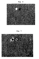
- the resulting monitor image is in Fig. 7 illustrated. The two defects are clearly highlighted as a bright or dark spot. This allows a safe and accurate representation of defects and avoids the danger of being at the inspection of the object will be overlooked structural errors due to blurred appearance.
- phase difference angle ⁇ or the 2 ⁇ / n-modulated difference angle ⁇ as an argument in a sine function to perform a sine transform. This must be done point by point.
- the transformation is: ⁇ x y ⁇ sin ⁇ x y ,
- the amplitude of the interference lines is normalized, ie the amplitude of the sine modulation is constant everywhere in the picture regardless of the location. The result is a good readable image, especially flaw image ( Fig. 8 ).
- the number of interference lines also increases with increasing n.
- the image processing device 9, i. the program running on the computer 10 may be such that the choice of the modulation is possible, for example by input of the factor n.
- the program may be such that between playback, the phase difference angle (with and without modulation) and the playback of a sinustransform Being image can be switched.
- Fig. 1 is based on a measuring head 8 with Michelson interferometer.
- a measuring head 8 can be used with an interferometer 14, in which a light beam is split into partial beams A, B, which are first combined at the CCD matrix 25 to form an interference pattern.
- the interferometer 14 has a recording lens 41, which directs a light beam onto a beam splitter 42.
- the partial beams A and B are formed.
- the partial beam A is forwarded to a tilting mirror 43 and deflected approximately at right angles.
- the partial beam B initially strikes a mirror 44 which is displaceably mounted with a drive, for example a piezo drive, in order to be reflected at an acute angle.
- a measuring system is used in particular for the detection of defects on test objects.
- the measurement object 1 is uniformly illuminated from a lighting unit E which contains a plurality of laser diodes 2, 3, 4, 5, 6.
- the beam cones of the individual lasers overlap strongly, which provides homogeneous illumination even with large exposure angles and changing imaging ratios due to different object sizes and distances.
- the measuring object 1 is observed interferometrically. From individual images phase difference images are determined. These are 2 ⁇ / n-modulated, which in particular in the range of defects phase jumps arise, which give particularly good contrasts.
Landscapes
- Physics & Mathematics (AREA)
- General Physics & Mathematics (AREA)
- Investigating Materials By The Use Of Optical Means Adapted For Particular Applications (AREA)
- Length Measuring Devices By Optical Means (AREA)
- Instruments For Measurement Of Length By Optical Means (AREA)
- Analysing Materials By The Use Of Radiation (AREA)
Abstract
Description
Die Erfindung betrifft eine Vorrichtung und ein Verfahren zum Untersuchen von Objekten. Insbesondere betrifft die Erfindung eine Vorrichtung und ein Verfahren zur Untersuchung von an Objekten mit diffus streuender Oberfläche auftretenden Verformungen.The invention relates to a device and a method for examining objects. In particular, the invention relates to a device and a method for the investigation of deformations occurring on objects with a diffusely scattering surface.
Nicht zerstörende Objektprüfungen sind insbesondere dort praktisch interessant, wo Qualitätsprüfungen an Werkstücken oder anderweitigen Arbeitsobjekten vorzunehmen sind. Beispielsweise stellt sich in der Praxis die Aufgabe, Reifen auf Fehlstellen zu untersuchen.Non-destructive object checks are particularly interesting where quality checks on workpieces or other work objects are to be carried out. For example, in practice the task is to examine tires for defects.
Dazu ist es aus der
Zur Beleuchtung der Objektoberfläche werden mehrere Laserdioden eingesetzt, die jeweils einen Leuchtfleck erzeugen. Die Leuchtflecke grenzen aneinander und überlappen sich allenfalls in Randzonen. Die beleuchteten Teilflächen setzen die Gesamtfläche zusammen. Die Abbildungsqualität der Einrichtung ist eingeschränkt.To illuminate the object surface, a plurality of laser diodes are used, each of which generates a light spot. The luminescent spots adjoin one another and at most overlap in peripheral zones. The illuminated partial surfaces combine the total area. The imaging quality of the device is limited.
Aus der
Davon ausgehend ist es Aufgabe der Erfindung, eine Vorrichtung und ein Verfahren zum Beobachten von Objektoberflächen zu schaffen, die bzw. das eine verbesserte Bildqualität aufweist.On this basis, it is an object of the invention to provide an apparatus and a method for observing object surfaces, which has an improved image quality.
Diese Aufgabe wird mit der Vorrichtung nach Anspruch 1 und dem Verfahren nach Anspruch 16 gelöst.This object is achieved with the device according to
Die erfindungsgemäße Vorrichtung weist einen Messkopf auf, der anhand des von der Objektoberfläche rückgestreuten Lichts ein Interferenzbild erzeugt. Ein elektronischer Bildsensor, der in den Messkopf integriert sein kann, erfasst das Interferenzbild und wandelt es in entsprechende elektrische Signale um, die dann weiter auswertbar sind.The device according to the invention has a measuring head which generates an interference image on the basis of the light backscattered by the object surface. An electronic image sensor, which can be integrated in the measuring head, detects the interference pattern and converts it into corresponding electrical signals, which can then be further evaluated.
Das von dem Messkopf erfasste Bildfeld wird von einer Beleuchtungseinheit beleuchtet, die mehrere Laserdioden aufweist. Diese sind so angeordnet, dass sie einen gemeinsamen Leuchtfleck bilden. Dieser ist gleichmäßig,ausgeleuchtet, so dass innerhalb des Leuchtflecks nur geringe Helligkeitsunterschiede anzutreffen sind. Dies wird durch eine relativ große Überlappung der aus den einzelnen Laserdioden austretenden Lichtbündel erreicht. Der gemeinsame Leuchtfleck ist nicht in Einzelleuchtflecke unterteilt.The image field captured by the measuring head is illuminated by a lighting unit which has a plurality of laser diodes. These are arranged so that they form a common spot. This is uniform, illuminated, so that within the light spot only small differences in brightness can be found. This is achieved by a relatively large overlap of the light beams emerging from the individual laser diodes. The common spot is not subdivided into single spot spots.
Durch die gleichmäßige Ausleuchtung der zu untersuchenden Objektoberfläche wird trotz fehlender Kohärenz der einzelnen die Oberfläche treffenden Lichtanteile eine erhöhte Bildqualität erreicht. In dem erzeugten Interferenzbild sind sowohl in Bildmitte als auch an den Bildrändern die gewünschten Verformungen gut zu erkennen.Due to the uniform illumination of the object surface to be examined, an increased image quality is achieved despite the lack of coherence of the individual light components striking the surface. In the generated interference image, the desired deformations are clearly visible both in the center of the image and at the edges of the image.
Die Lichtbündel der.Laserdioden können so stark überlappen, dass mehr als die Hälfte der Fläche des Leuchtflecks Licht von zwei Laserdioden erhält. Es ist wenigstens ein Bereich vorhanden der von dem Licht von mehr als zwei Laserdioden getroffen wird. Die Ausrichtung wird zweckmäßigerweise in den meisten Fällen auf gleichmäßige Helligkeitsverteilung ausgerichtet. Dabei ist es auch möglich, nahezu die gesamte Fläche des Leuchtflecks von mehr als zwei Dioden und auch von unterschiedlich vielen Dioden beleuchten zu lassen.The light beams of the laser diodes can overlap so strongly that more than half of the area of the light spot receives light from two laser diodes. There is at least one area hit by the light from more than two laser diodes. The orientation is expediently aligned in most cases to uniform brightness distribution. It is also possible to illuminate almost the entire surface of the light spot of more than two diodes and also of different numbers of diodes.
Es ist möglich, die Laserdioden der gesamten Gruppe gleichzeitig, vorzugsweise im Dauerbetrieb, leuchten zu lassen. Bei einer abgewandelten Ausführungsform können die Laserdioden pulsierend betrieben werden. Dadurch ist eine höhere Lichtausbeute für den Moment der Bildaufnahme möglich, wodurch entweder das beobachtete Objektfeld vergrößert oder die Beleuchtungsleistung verkleinert oder die Belichtungszeit verkürzt werden kann.It is possible to make the laser diodes of the entire group shine simultaneously, preferably in continuous operation. In a modified embodiment, the laser diodes can be operated pulsating. As a result, a higher light output for the moment of image acquisition is possible, which either increases the observed object field or the illumination power can be reduced or the exposure time can be shortened.
Alternativ ist es möglich, die Laserdioden derart anzusteuern oder beispielsweise mit einer Shuttervorrichtung derart anzuordnen, dass das Licht der Laserdioden der Gruppe zeitlich versetzt auf die Objektoberfläche trifft. Die entstehenden Einzelinterferogramme können an dem Bildsensor überlagert und summiert (integriert) oder, je nach Hardware, einzeln aufgenommen und in einem Rechner miteinander kombiniert werden. Wie bei Dauerbeleuchtung ergibt sich insgesamt ein gleichmäßig ausgeleuchtetes Feld. Die Laserdioden können ruhend oder bewegt angeordnet sein.Alternatively, it is possible to control the laser diodes in such a way or to arrange them, for example, with a shutter device such that the light of the laser diodes of the group strikes the object surface with a time offset. The resulting Einzelinterferogramme can be superimposed on the image sensor and summed (integrated) or, depending on the hardware, individually recorded and combined in a computer with each other. As with continuous lighting, the result is a uniformly illuminated field. The laser diodes can be arranged stationary or moved.
Der Bildsensor ist vorzugsweise an eine Bildauswerteeinrichtung angeschlossen, die anhand mehrerer aufgenommener Interferenzbilder eine verformung der Objektoberfläche bestimmt. Dies ist insbesondere in Fällen zweckmäßig, bei denen die Struktur oder Form der unverformten Objektoberfläche ohne Interesse ist. Solche Messungen sind beispielsweise bei der Werkstück- oder Materialprüfung zweckmäßig. Z.B. können sie dazu eingesetzt werden, Fehlstellen an Reifen zu erkennen. Die zu untersuchende Reifenoberfläche wird dabei bei zwei voneinander verschiedenen Umgebungsdrücken aufgenommen. Entstehende Verformungen werden sichtbar gemacht.The image sensor is preferably connected to an image evaluation device, which determines a deformation of the object surface on the basis of a plurality of recorded interference images. This is particularly useful in cases where the structure or shape of the undeformed object surface is of no interest. Such measurements are for example the workpiece or material testing appropriate. For example, they can be used to detect defects on tires. The tire surface to be examined is recorded at two different ambient pressures. Emerging deformations are made visible.
Das Interferometer kann ohne direkten Interferenzstrahl arbeiten. Dies ist möglich, wenn der von dem Objekt rückgestreute Strahl in zwei Teilstrahlen aufgeteilt wird, von denen einer einer Phasenverschiebung unterworfen wird. Die Phasenverschiebung ist vorzugsweise steuer- oder kontrollierbar. Dazu dient vorteilhafterweise eine Einrichtung zur Phasenverschiebung, beispielsweise ein Spiegel, der von einem Piezo-Aktuator verstellt wird. Es ist möglich, als Interferometer ein Michelson-Interferometer zu verwenden. Eine besonders vorteilhaft Ausführungsform nutzt jedoch als Interferometer eine Anordnung, bei der der Objektlichtstrahl in zwei Teilstrahlen aufgeteilt wird, die auf unterschiedlichen Wegen zu dem Bildsensor gelangen und sich erst dort wieder treffen. Dies hat den Vorteil, dass Lichtverluste, wie sie beim Michelson-Interferometer beim Zusammenführen der Teilstrahlen im Strahlteiler auftreten, vermieden werden.The interferometer can work without a direct interference beam. This is possible if the beam backscattered by the object is divided into two sub-beams, one of which is subjected to a phase shift. The phase shift is preferably controllable or controllable. Advantageously, a device for phase shifting, for example a mirror, which is adjusted by a piezoelectric actuator, is used for this purpose. It is possible to use a Michelson interferometer as the interferometer. However, a particularly advantageous embodiment uses as an interferometer, an arrangement in which the object light beam is split into two sub-beams, which arrive at different ways to the image sensor and only meet again there. This has the advantage that light losses, such as occur in the Michelson interferometer when merging the partial beams in the beam splitter are avoided.
Der Bildsensor ist an eine Bildauswerteeinrichtung angeschlossen, die vorzugsweise eine Recheneinheit aufweist. Die Recheneinheit, beispielsweise ein entsprechend leistungsfähiger Computer, arbeitet ein Programm ab, das die Bildverarbeitung bewerkstelligt. Dabei wird beispielsweise aus mehreren, von dem ruhenden Objekt mit gegeneinander verschobener Phasenlage aufgenommenen Bildern ein Phasenbild berechnet. Die Phasenlagen einzelner Bildpunkte sind in der Regel stochastisch verteilt und geben keinen direkten Aufschluss über das Objekt. Wird die Objektoberfläche jedoch verformt oder um einen geringen Betrag auf den Messkopf hin oder von diesem weg verschoben und wird in diesem Zustand beispielsweise durch Verknüpfung mehrerer, durch Phasenverschiebung veränderter Interferenzen untereinander ein Phasenbild erhalten, kann aus beiden erhaltenen Phasenbildern ein Phasendifferenzbild bestimmt werden. Das Phasendifferenzbild gibt Aufschluss über lokale Verschiebungen oder Verformungen und kann zur Anzeige gebracht werden. Dazu wird dem jeweiligen Phasendifferenzwinkel des Bildpunkts ein Grauwert zugeordnet, der auf einer Wiedergabeeinrichtung an der betreffenden Stelle angezeigt wird. Beispielsweise wird einem Phasendifferenzwinkel von Null der Anzeigewert schwarz und dem Phasendifferenzwinkel von 2π der Grauwert weiß zugeordnet.The image sensor is connected to an image evaluation device, which preferably has a computing unit. The arithmetic unit, for example, a correspondingly powerful computer, executes a program that accomplishes the image processing. In this case, for example, a phase image is calculated from a plurality of images recorded by the stationary object with phase shift shifted relative to one another. The phase positions of individual pixels are usually stochastically distributed and give no direct information about the object. If, however, the object surface is deformed or displaced by a small amount toward or away from the measuring head, and a phase image is obtained in this state, for example by linking a plurality of interferences which have been changed by phase shifting, a phase difference image can be determined from the two phase images obtained. The phase difference image provides information about local displacements or deformations and can be displayed. For this purpose, a gray value is assigned to the respective phase difference angle of the pixel, which is displayed on a reproduction device at the relevant point. For example, a phase difference angle of zero, the display value is black and the phase difference angle of 2π gray value assigned to white.
Bei einer vorteilhaften Ausgestaltung des Verfahrens und der zugehörigen Vorrichtung werden die Phasendifferenzwinkel, bevor sie zur Anzeige gebracht werden, 2π/n-moduliert. Dazu werden die Differenzwinkel des Phasendifferenzbildes punktweise einer Modulo 2π/n-Division unterworfen. Dies bedeutet, dass der Phasendifferenzwinkel durch 2π/n dividiert wird und der verbleibende Rest den Ergebniswert bildet. Dieser Ergebniswert wird mit dem Faktor n multipliziert und ergibt den 2π/n-modulierten Wert, der im Wertbereich von Null bis 2 π/n mit Grauwerten zwischen schwarz und weiß zur Anzeige gebracht wird. Bedarfsweise kann auch eine farbige Anzeige gewählt werden. Der Faktor n ist dabei vorzugsweise eine ganze Zahl größer 1. Dies ergibt eine Verstärkung der in dem Phasendifferenzbild vorhandenen und sichtbaren Objektverformungen und somit eine deutlichere Erkennbarkeit von Fehlstellen an dem Objekt.In an advantageous embodiment of the method and the associated device, the phase difference angles, before they are displayed, 2π / n-modulated. For this purpose, the difference angles of the phase difference image are subjected point by point to a modulo 2π / n division. This means that the phase difference angle is divided by 2π / n and the remaining remainder forms the result value. This result value is multiplied by the factor n and gives the 2π / n-modulated value, which is displayed in the value range from zero to 2 π / n with gray values between black and white. If necessary, a colored display can also be selected. The factor n is preferably an integer greater than 1. This results in an amplification of the existing and visible in the phase difference image object deformations, and thus a clearer recognizability of defects on the object.
Es ist alternativ möglich, die Phasendifferenz oder die 2 π/n-modulierten Werte der Phasendifferenzen mit einer Sinusfunktion zu modulieren und den erhaltenen Wert zur Anzeige zu bringen. Es ergibt sich dann ein Streifenmuster, das die Objektverformung kennzeichnet. Je höher n gewählt wird, desto höher ist die Auflösung, d.h. desto mehr Streifen entfallen auf eine bestimmte Objektverformung. Hierbei ist es zweckmäßig, wenn der Bediener den Faktor n durch geeignete Eingabemittel wählen kann. Der Faktor kann beispielsweise auch nach einer Bildaufnahme umgeschaltet werden, um ein und denselben Testlauf, d.h. die gleiche Objektverformung mit unterschiedlichen Modulationen darstellen zu können.Alternatively, it is possible to modulate the phase difference or the 2 π / n modulated values of the phase differences with a sine function and display the obtained value. This results in a fringe pattern that characterizes the object deformation. The higher n is selected, the higher the resolution, i. the more stripes account for a given object deformation. In this case, it is expedient for the operator to be able to select the factor n by means of suitable input means. For example, the factor may also be switched after image acquisition to perform the same test run, i. to represent the same object deformation with different modulations.
Das Verfahren ist für Prüfobjekte mit diffus streuender Oberfläche geeignet und ergibt eine bildhafte Darstellung von Phasendifferenzwinkeln. Dies gestattet dem Bediener ein leichtes Erkennen von Strukturfehlern im vermessenen Objekt. Dabei ist dieses Verfahren für beliebige Prüfobjekte bzw. Fehlergrößen anwendbar und erfordert einen geringen Rechenaufwand, so dass die Ergebnisdarstellung quasi in Echtzeit gewährleistet ist.The method is suitable for test objects with a diffusely scattering surface and gives a pictorial representation of phase difference angles. This allows the operator to easily detect structural errors in the measured object. In this case, this method is applicable for any test objects or error sizes and requires a low computational effort, so that the result representation is guaranteed virtually in real time.
Bei einer weiteren vorteilhaften Ausgestaltung der Erfindung wird der anzuzeigende Wert so skaliert, dass der darstellbare Grauwertbereich des Bildverarbeitungssystems vollständig ausgenutzt wird. Zur Verbesserung der Sichtbarkeit von Fehlstellen kann der einem Winkel der Größe Null entsprechende Grauwert oder Farbwert vom Benutzer interaktiv eingestellt werden.In a further advantageous embodiment of the invention, the value to be displayed is scaled so that the displayable gray value range of the image processing system is fully utilized. To improve the visibility of defects, the greyscale value or color value corresponding to an angle of zero size can be interactively set by the user.
Das 2π/n-modulierte Phasendifferenzbild kann auch unmittelbar aus den phasenverschobenen Intensitätsbildern einer ersten Aufnahmeserie bei einem ersten Objektzustand und einer zweiten Serie phasenverschobener Aufnahmen (Intensitätsbildern) bei einem zweiten Objektzustand gewonnen werden. Die Gleichungen zur 2π/n-Modulation werden dazu in die Gleichungen zur Erzeugung der Phasendifferenzbilder aus den Intensitätsbildern eingesetzt.The 2π / n-modulated phase difference image can also be obtained directly from the phase-shifted intensity images of a first series of images in a first object state and a second series of phase-shifted images (intensity images) in a second state of the object. The equations for 2π / n modulation are used in the equations for generating the phase difference images from the intensity images.
Bei einer vorteilhaften Ausführungsform werden alle Punkte des Leuchtflecks, die von der Kamera oder einer anderen Bilderfassungseinrichtung erfasst werden, von wenigstens zwei Laserdioden beleuchtet. Dadurch können auch dann ordentliche Messergebnisse erhalten werden, wenn eine Laserdiode ausgefallen ist. Das Licht ist somit in dem gesamten von der Kamera erfassten Bereich inkohärent.In an advantageous embodiment, all points of the luminous spot, which are detected by the camera or another image capture device, are illuminated by at least two laser diodes. As a result, proper measurement results can be obtained even if a laser diode has failed. The light is thus in the whole of the camera covered area incoherently.
Weitere Einzelheiten vorteilhafter Ausführungsformen der Erfindung sind Gegenstand von Unteransprüchen, der Zeichnung oder der Beschreibung.Further details of advantageous embodiments of the invention are the subject of subclaims, the drawings or the description.
In der Zeichnung sind Ausführungsbeispiele des Gegenstandes der Erfindung veranschaulicht. Es zeigen:
-
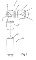
Fig. 1 eine erfindungsgemäße Vorrichtung zur Ermittlung von Verformungen an einer Objektoberfläche, in schematisierter Darstellung, -
Fig. 2 eine Beleuchtungseinheit und eine von dieser beleuchtete Objektoberfläche zur interferometrischen Auswertung von Oberflächenverformungen, in schematisierter Prinzipdarstellung, -
Fig. 3 eine Objektoberfläche mit einem auf sie fallenden Leuchtfleck einer Beleuchtungseinheit nachFig. 2 , -
Fig. 4 einen Messkopf der Vorrichtung nachFig. 1 , in schematisierter gesonderter Darstellung, -
Fig. 5 Grauwerte G in Abhängigkeit von Phasendifferenzwinkeln Δπ bei unterschiedlichen Modulationen, -
Fig. 6 ein 2 π/n-moduliertes Bild einer Objektoberfläche, -
Fig. 7 ein π-moduliertes Fehlstellenbild der gleichen Objektoberfläche, -
Fig. 8 ein sinustransformiertes moduliertes Phasendifferenzbild, gebildet aus dem Fehlstellenbild nachFig. 3 und -
Fig. 9 eine weitere Ausführungsform des Interferometers in schematischer Darstellung:
-
Fig. 1 a device according to the invention for determining deformations on an object surface, in a schematic representation, -
Fig. 2 a lighting unit and an illuminated by this object surface for the interferometric evaluation of surface deformations, in a schematic outline representation, -
Fig. 3 an object surface with a falling light spot of a lighting unit afterFig. 2 . -
Fig. 4 a measuring head of the device according toFig. 1 in a schematic separate representation, -
Fig. 5 Gray values G as a function of phase difference angles Δπ for different modulations, -
Fig. 6 a 2π / n modulated image of an object surface, -
Fig. 7 a π-modulated defect image of the same object surface, -
Fig. 8 a sinusoidally modulated modulated phase difference image formed from the defect image afterFig. 3 and -
Fig. 9 a further embodiment of the interferometer in a schematic representation:
In
Zur Beobachtung der Oberfläche des Prüfobjekts 1 dient ein Messkopf 8, der an einer Bildauswerteeinheit 9 angeschlossen ist. Zu dieser gehören ein Computer 10 und ein Monitor 11 sowie eine Eingabeeinrichtung, beispielsweise eine Tastatur 12.To observe the surface of the
Der Messkopf 8 enthält ein Interferometer 14, das über ein Objektiv 15 von der Objektoberfläche rückgestreute Lichtstrahlung erhält.The measuring
In
Das in
Der Spiegel 19 ist ortsfest gelagert, während der Spiegel 20 durch eine, beispielsweise aus
Der Strahlteiler 18 führt die von den Spiegeln 19, 20 reflektierten Teilstrahlen wieder zusammen und über ein Abbildungsobjektiv 23 einer Kamera 24 zu. Die Kamera 24 enthält als Bildsensor eine CCD-Matrix 25 und die entsprechenden Elektronikbausteine zur Ansteuerung derselben. Die Kamera 24 ist mit dem Computer 10 verbunden.The
Das insoweit beschriebene Mess-System arbeitet wie folgt:The measuring system described so far works as follows:
Zur Bestimmung von Objektfehlstellen wird das Objekt 1 vor dem Messkopf 8 platziert und mit den Laserdioden 2, 3, 4, 5, 6 beleuchtet. Die Laserdioden 2, 3, 4, 5, 6 können dabei im Dauerbetrieb betrieben werden, d.h. gleichzeitig dauernd leuchten. Auf dem Objekt 1 wird dadurch der Leuchtfleck 7 erzeugt, der auf den auf Fehlstellen zu untersuchenden Bereich fällt. Ohne dass das Objekt 1 in irgendeiner Weise merklich bewegt würde, werden nun mehrere Bilder von der Objektoberfläche aufgenommen. Dazu wird bei gegebener Positionierung der Spiegel 19, 20 zunächst ein erstes Bild aufgenommen und abgespeichert. Das von dem Bildsensor 25 erfasste Bild ist ein Interferenzmuster der Objektoberfläche, das stochastisch verteilte helle, dunkle und graue Bereiche, sogenannte "Speckles" enthält. Ist das Bild aufgenommen, steuert der Rechner den Spiegel 20 so an, dass er um einen bekannten Betrag verschoben wird. Es ergibt sich eine definierte Phasenverschiebung zwischen den beiden Teilstrahlen der Spiegel 19 und 20. Das Speckle-Bild ändert sich dabei, indem die einzelnen Speckles geänderte Helligkeit annehmen. Die Speckle bleiben selbst jedoch am gleichen Ort.To determine object defects, the
Ist das Bild aufgenommen, wird eine weitere Verstellung des Spiegels 20 aufgenommen, um ein drittes Bild aufzunehmen. Ist das dritte Bild aufgenommen, wird nach einer nochmaligen Verstellung des Spiegels 20 um einen bekannten Phasenbetrag ein viertes Bild aufgenommen. Aus den vier unterschiedlichen Speckle-Bildern berechnet der Computer 10 die für jeden Speckle oder jeden Pixel gültigen Phasenwinkel.Once the image is taken, another adjustment of the
Ist auf diese Weise das erste Phasendifferenzbild erzeugt, wird das zu prüfende Objekt 1 beispielsweise mit einer Prüfkraft beaufschlagt. Dies kann im Falle von Reifen dadurch geschehen, dass der Umgebungsdruck geändert wird. Es ergeben sich dadurch an der Oberfläche des Objekts 1 charakteristische Verformungen, die insbesondere an Fehlstellen größer sind als die Verformung der Umgebung. Ist das Objekt 1 verformt, werden wiederum mehrere, durch Verstellung des Spiegels 20 phasenverschobene Speckle-Bilder aufgenommen, aus denen dann die geänderten Phasenwinkel pixelweise berechnet werden. Es ergibt sich ein zweites Phasenwinkelbild. Zur Bestimmung der Oberflächenverformung wird aus beiden erhaltenen Phasenbildern nun ein Phasendifferenzbild erzeugt. Dies erfolgt bildpunkt- oder pixelweise. Es wird die Phasenwinkeldifferenz zwischen verformtem und unverformtem Zustand für jeden Bildpunkt bestimmt. Ist auf diese Weise das Phasendifferenzbild erhalten, kann es auf dem Monitor 11 zur Anzeige gebracht werden. Ein nach diesem Verfahren erzeugtes Fehlstellenbild ist in
Eine Betonung der Fehlstellen wird erhalten, wenn der Computer 10 die Phasendifferenzbilder nachbearbeitet. In der Nachbearbeitung wird dem Phasendifferenzbildern Δϕ(x, y) ein 2 π/nmoduliertes Phasendifferenzbild erzeugt. Dazu wird für jeden Bildpunkt folgende Gleichung abgearbeitet:![]()
![]()
- Δϕ x,y) :
- Phasendifferenzwinkel am Punkt (x,y)
- ϕ1(x,y) :
- Phasendifferenzwinkel am Punkt (x,y)
im Zustand 1 - ϕ2(x,y) :
- Phasendifferenzwinkel am Punkt (x,y)
im Zustand 2 - ϕdiff(x,y) :
- Phasendifferenzwinkel mit 2π/n-Modulation am Punkt (x,y)
- n :
- ganze
Zahl größer gleich 1 - S :
- Umrechnungsfaktor von Phasendifferenzwinkel in Grauwert
- MOD :
- Modulo-Operator.
- Δφ x, y):
- Phase difference angle at the point (x, y)
- φ 1 (x, y):
- Phase difference angle at point (x, y) in
state 1 - φ 2 (x, y):
- Phase difference angle at point (x, y) in
state 2 - φ diff (x, y):
- Phase difference angle with 2π / n modulation at point (x, y)
- n:
- integer greater than or equal to 1
- S:
- Conversion factor of phase difference angle in gray value
- MOD:
- Modulo operator.
Diese Operation ist in
Außerdem ist es möglich, die erhaltenen Phasendifferenzwinkel Δϕ oder die 2π/n-modulierten Differenzwinkel Δϕ als Argument in eine Sinusfunktion einzusetzen, um eine Sinustransformation durchzuführen. Dies muss wiederum punktweise geschehen. Die Transformation lautet:![]()
![]()
Die Amplitude der Interferenzlinien ist normiert, d.h. die Amplitude der Sinusmodulation ist im Bild unabhängig vom Ort überall konstant. Es ergibt sich ein gut lesbares Bild, insbesondere Fehlstellenbild (
Die Bildverarbeitungseinrichtung 9, d.h. das auf dem Computer 10 laufende Programm kann so beschaffen sein, dass die Wahl der Modulation beispielsweise durch Eingabe des Faktors n möglich ist. Außerdem kann das Programm so beschaffen sein, dass zwischen Wiedergabe der Phasendifferenzwinkel (mit und ohne Modulation) und der Wiedergabe eines sinustransformierten Bilds umgeschaltet werden kann.The
In
Ein Mess-System dient insbesondere der Erfassung von Fehlstellen an Prüfobjekten. Das Messobjekt 1 wird dazu aus einer Beleuchtungseinheit E, die mehrere Laserdioden 2, 3, 4, 5, 6 enthält, gleichmäßig ausgeleuchtet. Die Strahlkegel der einzelnen Laser überlappen sich stark, was eine homogene Beleuchtung auch bei großen Aufnahmewinkeln und sich ändernden Abbildungsverhältnissen durch unterschiedliche Objektgrößen und Abstände erbringt. Das Messobjekt 1 wird interferometrisch beobachtet. Aus einzelnen Bildern werden Phasendifferenzbilder ermittelt. Diese werden 2π/n-moduliert, wodurch insbesondere im Bereich von Fehlstellen Phasensprünge entstehen, die besonders gute Kontraste ergeben.A measuring system is used in particular for the detection of defects on test objects. For this purpose, the
Claims (24)
- Device for determining deformations on the surface of an object to be tested, in particular a diffusely scattering object surface, with
an illuminating unit (E), which has an array of laser diodes (2, 3, 4, 5, 6) which respectively generate a light cone (2a, 3a, 4a, 5a, 6a);
a measuring head (8) which has an interferometer (14), wherein the interferometer (14) generates an interference image from the light reflected by the surface of the object to be tested;
an electronic image sensor (25), which is arranged in the optical path of the interferometer (14), so that the interference image is captured by the image sensor (25), and,
wherein the laser diodes (2, 3, 4, 5, 6) are arranged such that the light cones (2a, 3a, 4a, 5a, 6a) fade into one another and overlap multiply on the surface of the object to be tested and generate a joint illuminating spot (7) with a uniform brightness distribution, which has at least a region that is illuminated by the light of at least two laser diodes (2, 3, 4, 5, 6). - Device according to Claim 1, characterised in that the illuminating spot (7) has several regions, which are illuminated by the light from more than two laser diodes.
- Device according to Claim 1, characterised in that the laser diodes (2, 3, 4, 5, 6) of the array illuminate in continuous operation.
- Device according to Claim 1, characterised in that the laser diodes (2, 3, 4, 5, 6) of the array are operated in a pulsating manner.
- Device according to Claim 1, characterised in that every point of the illuminating spot (7) is illuminated by at least two laser diodes (2, 3, 4, 5, 6), in the region of the illuminating spot (7) detected by the image sensor (25).
- Device according to Claim 1, characterised in that the image sensor (25) is connected to an image evaluation means (9), which determines a deformation of the object surface on the basis of several recorded interference images.
- Device according to Claim 1, characterised in that the interferometer (14) has a means (20, 21) for phase shifting two component beams relative to one another.
- Device according to Claim 6, characterised in that the image evaluation means (9) has a calculation unit (10), which is configured to calculate a phase pattern form several images taken of the object in different phase positions.
- Device according to Claim 8, characterised in that the calculation unit (10) is configured to determine a phase difference pattern Δϕ(x, y) from at least two different phase patterns, preferably obtained in different object states, by subtracting the phase angle ϕ1(x, y) of an image point (x, y) assigned to a first object state from the phase angle ϕ2(x, y) of the same image point (x, y) assigned to a second object state.
- Device according to Claim 9, characterised in that the calculation unit (10) divides the phase difference values point by point modulo 2π/n and multiplies the result by a factor n and also supplies the value obtained.
- Device according to Claim 10, characterised in that n is a whole number, which is greater than or equal to 1.
- Device according to one of the Claims 9 to 11, characterised in that the calculation unit (10) puts the phase differences Δϕ(x, y) or the 2π/n-modulated values pixel by pixel as argument into a sine function and supplies the value obtained.
- Device according to one of the Claims 8 to 12, characterised in that the calculation unit (10) is connected to a display means (11) and that the supplied value is displayed by the display means (11).
- Device according to claim 1, characterised in that the interferometer (14) is structured in the manner of a Michelson interferometer.
- Device according to Claim 1, characterised in that the interferometer (14) has a beam splitter (18), which divides the light coming from the object surface into two component beams, which run through different paths up to the image sensor (25) and meet on the image sensor (25) for generation of an interference pattern.
- Procedure for determining deformations on the surface of an object to be tested, in particular a diffusely scattering object surface, by means of interferometric surface observation or imaging, which has the following steps:a) the surface of the object to be tested is illuminated by an array of laser diodes (2, 3, 4, 5, 6) which respectively generate a light cone (2a, 3a, 4a, 5a, 6a);b) the light of the laser diodes (2, 3, 4, 5, 6) is directed to a joint illuminating spot (7) on the object to be tested, wherein the laser diodes (2, 3, 4, 5, 6) are arranged in such a way that the light cones (2a, 3a, 4a, 5a, 6a) merge into each other and overlap multiply on the surface of the object to be tested and generate a joint illuminating spot (7) with a uniform brightness distribution, which has at least a region that is illuminated by the light of at least two laser diodes (2, 3, 4, 5, 6).c) an interference image is generated from the light reflected by the surface of the object to be tested by superposing the individual interferograms obtained.
- Procedure according to Claim 16, characterised in that the illuminating spot (7) has several regions, which are illuminated by the light from more than two laser diodes.
- Procedure according to Claim 16, characterised in that the laser diodes (2, 3, 4, 5, 6) of the array illuminate simultaneously, preferably in continuous operation.
- Procedure according to claim 16, characterised in that the laser diodes (2, 3, 4, 5, 6) of the array are operated in a pulsating manner.
- Procedure according to Claim 16, characterised in thatphase patterns ϕ(x, y) are obtained from several mutually phase-shifted recorded images of the object surface in one and the same state, anda phase difference pattern Δϕ(x, y) is determined at least from two different phase patterns ϕ1(x, y), ϕ2(x, y)), preferably obtained in different object states, by subtracting the phase angle Δϕ1(x, y) of an image point (x, y) assigned to a first object state from the phase angle Δϕ2(x, y) of the same image point (x, y) assigned to a second object state.
- Procedure according to Claim 20, characterised in that
the phase difference values are divided point by point by 2π(nεN, n≥1);
the remainder multiplied by a factor n, and
that the value obtained is supplied as a 2-π/n-mudulated value. - Procedure according to claim 20, characterised in that a 2π/n-mudulated phase difference pattern is obtained from phase-shifted recorded intensity images.
- Procedure according to one of the Claims 20 to 22, characterised in that the phase differences Δϕ(x, y) or the 2-π/n-modulated values are put pixel by pixel as an argument into a sine function and the value obtained is supplied.
- Procedure according to one of the Claims 21 to 23, characterised in that the supplied value is displayed by a display means (11).
Priority Applications (1)
| Application Number | Priority Date | Filing Date | Title |
|---|---|---|---|
| DE29924939U DE29924939U1 (en) | 1998-12-23 | 1999-12-23 | Device to measure deformations on object surface, especially diffusely reflecting object surface; has interferometer, electric image sensor to measure interference pattern and several laser diodes to form common light spot on object |
Applications Claiming Priority (2)
| Application Number | Priority Date | Filing Date | Title |
|---|---|---|---|
| DE19859725 | 1998-12-23 | ||
| DE19859725A DE19859725C2 (en) | 1998-12-23 | 1998-12-23 | Device for determining deformations on an object surface, in particular a diffusely scattering object surface, and use of the device |
Publications (4)
| Publication Number | Publication Date |
|---|---|
| EP1014036A2 EP1014036A2 (en) | 2000-06-28 |
| EP1014036A3 EP1014036A3 (en) | 2002-05-02 |
| EP1014036B1 EP1014036B1 (en) | 2004-01-07 |
| EP1014036B2 true EP1014036B2 (en) | 2010-04-21 |
Family
ID=7892434
Family Applications (1)
| Application Number | Title | Priority Date | Filing Date |
|---|---|---|---|
| EP99125794A Expired - Lifetime EP1014036B2 (en) | 1998-12-23 | 1999-12-23 | Device and procedure to examine an object |
Country Status (4)
| Country | Link |
|---|---|
| US (1) | US6417916B1 (en) |
| EP (1) | EP1014036B2 (en) |
| AT (1) | ATE257582T1 (en) |
| DE (2) | DE19859725C2 (en) |
Families Citing this family (32)
| Publication number | Priority date | Publication date | Assignee | Title |
|---|---|---|---|---|
| US6717681B1 (en) * | 1999-03-31 | 2004-04-06 | Benjamin A. Bard | Portable real-time high-resolution digital phase-stepping shearography with integrated excitation mechanisms |
| DE10101057B4 (en) * | 2000-11-29 | 2004-01-15 | Steinbichler Optotechnik Gmbh | Method and device for detecting the deformation of objects |
| EP1215465A1 (en) | 2000-11-29 | 2002-06-19 | Steinbichler Optotechnik Gmbh | Method and apparatus for measuring the deformation of objects |
| EP1333260A3 (en) * | 2002-01-31 | 2004-02-25 | Canon Kabushiki Kaisha | Phase measuring method and apparatus |
| US7310139B2 (en) * | 2002-03-28 | 2007-12-18 | Takai Tofu & Soymilk Equipment Company Limited | Evaluation method and device for gel state or sol-gel state change of object |
| JP2004271381A (en) * | 2003-03-10 | 2004-09-30 | Fuji Photo Optical Co Ltd | Speckle interferometer device |
| DE10319099B4 (en) * | 2003-04-28 | 2005-09-08 | Steinbichler Optotechnik Gmbh | Method for interference measurement of an object, in particular a tire |
| JP2005134196A (en) * | 2003-10-29 | 2005-05-26 | Nec Electronics Corp | Non-destructive analysis method and non-destructive analysis device |
| DE10354582A1 (en) * | 2003-11-21 | 2005-06-30 | Hentze-Lissotschenko Patentverwaltungs Gmbh & Co.Kg | Arrangement and method for suppressing speckle structures of a pulsed laser beam |
| US7474297B2 (en) * | 2004-03-22 | 2009-01-06 | Avago Technologies Ecbu Ip (Singapore) Pte. | Contaminant-resistant optical mouse and cradle |
| US7423765B2 (en) * | 2004-07-31 | 2008-09-09 | Carl Zeiss Smt Ag | Optical system of a microlithographic projection exposure apparatus |
| US7791727B2 (en) * | 2004-08-16 | 2010-09-07 | Asml Netherlands B.V. | Method and apparatus for angular-resolved spectroscopic lithography characterization |
| US20080144036A1 (en) * | 2006-12-19 | 2008-06-19 | Asml Netherlands B.V. | Method of measurement, an inspection apparatus and a lithographic apparatus |
| DE102005032735B3 (en) * | 2005-06-16 | 2007-02-22 | Mähner, Bernward | Tire testing device using interferometric measurement, has positioning device arranged in additional chamber allowing tread of tire to be scanned from outside by measuring head |
| DE102005049607A1 (en) * | 2005-10-17 | 2007-04-19 | Steinbichler Optotechnik Gmbh | Method and device for detecting the deformation of objects |
| US7492450B2 (en) * | 2005-10-24 | 2009-02-17 | General Electric Company | Methods and apparatus for inspecting an object |
| DE102006014070B4 (en) | 2006-03-27 | 2008-02-07 | Mähner, Bernward | Device and method for testing a tire, in particular by means of an interferometric measuring method |
| DE102006014058B4 (en) | 2006-03-27 | 2008-04-17 | Mähner, Bernward | Apparatus and method for optically testing a tire |
| DE102006015123B4 (en) | 2006-03-31 | 2008-03-20 | Mähner, Bernward | Device and method for testing a tire, in particular by means of an interferometric measuring method |
| DE102006061003B4 (en) | 2006-12-22 | 2009-03-26 | Mähner, Bernward | Device for testing a test object, in particular a tire, by means of a non-destructive measuring method |
| DE102007009040C5 (en) | 2007-02-16 | 2013-05-08 | Bernward Mähner | Device and method for testing a tire, in particular by means of an interferometric measuring method |
| DE102007031774A1 (en) | 2007-07-07 | 2009-01-15 | Mähner, Bernward | High dynamic range imaging, to measure the shape or shape changes of objects, uses different illuminating lighting and a multiple light sensor scanned in steps to compensate for dark and bright areas |
| DE102007040353B3 (en) * | 2007-08-27 | 2009-04-23 | Mähner, Bernward | Test object e.g. off-the-road tire, testing device for e.g. earthmoving machine, has pressure chamber with hood having edge section arranged in recess filled with sealing compound for pressure tight sealing of hood with respect to base |
| DE102008037356C5 (en) | 2008-08-12 | 2020-09-17 | Bernward Mähner | Stacking module and centering module for a testing system for testing tires |
| DE102013102296B4 (en) | 2012-12-21 | 2018-11-08 | Bernward Mähner | Device and method for testing a tire by means of an interferometric measuring method |
| DE102013010402A1 (en) | 2013-06-21 | 2014-12-24 | Steinbichler Optotechnik Gmbh | Tire tester, tire tester and tire testing method |
| JP2016040541A (en) * | 2014-08-13 | 2016-03-24 | ソニー株式会社 | Signal processor, signal processing method and program |
| DE102018001255A1 (en) | 2018-02-18 | 2019-08-22 | Bernward Mähner | Method and device for investigating rotationally symmetrical test objects |
| US10962419B2 (en) * | 2019-04-09 | 2021-03-30 | Carl Zeiss Optotechnik GmbH | Method for testing a tire by interferometry |
| WO2023062096A1 (en) | 2021-10-12 | 2023-04-20 | Dengler, Stefan | Method for testing tyres |
| DE102022126613A1 (en) | 2022-10-12 | 2024-04-18 | Stefan Dengler | Procedure for testing tires |
| DE102023132675B3 (en) | 2023-11-23 | 2024-12-24 | Stefan Dengler | Device and method for testing a tire, in particular by means of an interferometric measuring method |
Citations (1)
| Publication number | Priority date | Publication date | Assignee | Title |
|---|---|---|---|---|
| DE4231578C2 (en) † | 1992-09-21 | 1995-06-29 | Nova C O R D Ag | Method for determining deformations on a test object with a diffusely scattering surface, in particular on tires, and device for carrying out the method |
Family Cites Families (7)
| Publication number | Priority date | Publication date | Assignee | Title |
|---|---|---|---|---|
| IT1135701B (en) * | 1981-03-23 | 1986-08-27 | Cise Spa | EQUIPMENT FOR DETECTION OF MOVEMENTS OF POINTS OF EXCITED STRUCTURES |
| DE4013309A1 (en) * | 1990-04-26 | 1991-10-31 | Zeiss Carl Fa | METHOD AND ARRANGEMENT FOR THE OPTICAL EXAMINATION OF TEST UNITS |
| DE4102881A1 (en) * | 1991-01-31 | 1992-08-06 | Man Technologie Gmbh | METHOD AND DEVICE FOR DETECTING THE SURFACE INFORMATION BY MEANS OF SPECKLE INTERFEROMETRY |
| JP3414417B2 (en) * | 1992-09-30 | 2003-06-09 | 富士通株式会社 | 3D image information transmission system |
| DE4446887A1 (en) * | 1994-12-28 | 1996-07-04 | Wolfgang Prof Dr Ing Steinchen | Non-destructive surface inspection by shearing speckle interferometry |
| DE19501073A1 (en) * | 1995-01-16 | 1996-08-01 | Nova C O R D Ag | Image processing method for determining the structural strength of a test object with a diffusely scattering surface |
| US6043870A (en) * | 1996-07-01 | 2000-03-28 | Cybernet Systems Corporation | Compact fiber optic electronic laser speckle pattern interferometer |
-
1998
- 1998-12-23 DE DE19859725A patent/DE19859725C2/en not_active Expired - Fee Related
-
1999
- 1999-12-23 EP EP99125794A patent/EP1014036B2/en not_active Expired - Lifetime
- 1999-12-23 DE DE59908245T patent/DE59908245D1/en not_active Expired - Lifetime
- 1999-12-23 AT AT99125794T patent/ATE257582T1/en not_active IP Right Cessation
-
2000
- 2000-05-09 US US09/566,727 patent/US6417916B1/en not_active Expired - Lifetime
Patent Citations (1)
| Publication number | Priority date | Publication date | Assignee | Title |
|---|---|---|---|---|
| DE4231578C2 (en) † | 1992-09-21 | 1995-06-29 | Nova C O R D Ag | Method for determining deformations on a test object with a diffusely scattering surface, in particular on tires, and device for carrying out the method |
Non-Patent Citations (3)
| Title |
|---|
| BISLE W.J.: "Optische Prüfung an Luftfahrtkomponenten: Weiterentwicklung des Scherografie-Prüfverfahrens für Nicht-Kooperative Oberflächen von Flugzeugstrukturen", DGLR JAHRESTAGUNG, DEUTSCHER LUFT- UND RAUMFAHRTKONGRESS 1998, 5 October 1998 (1998-10-05) - 8 October 1998 (1998-10-08), BREMEN † |
| STEINCHEN WOLFGANG ET AL: "Application of Laser Diodes in Digital Speckle Pattern Shearing Interferometry", vol. 3415, July 1998, QUEBEC, CANADA, article "SPIE Conference on Laser Diodes and Applications III" † |
| YANG, LIANGXIANG: "Fortschrittsberichte VDI Reihe 8", vol. 682, 1998, VDI VERLAG, DÜSSELDORF, article "Grundlagen und Anwendungen der Phasenschiebe-Shearografie zur zerstörungsfreien Werkstoffprüfung, Dehnungsmessung und Schwingungsanalyse" † |
Also Published As
| Publication number | Publication date |
|---|---|
| ATE257582T1 (en) | 2004-01-15 |
| DE59908245D1 (en) | 2004-02-12 |
| DE19859725C2 (en) | 2001-02-22 |
| DE19859725A1 (en) | 2000-07-06 |
| EP1014036A2 (en) | 2000-06-28 |
| EP1014036B1 (en) | 2004-01-07 |
| EP1014036A3 (en) | 2002-05-02 |
| US6417916B1 (en) | 2002-07-09 |
Similar Documents
| Publication | Publication Date | Title |
|---|---|---|
| EP1014036B2 (en) | Device and procedure to examine an object | |
| DE4231578C2 (en) | Method for determining deformations on a test object with a diffusely scattering surface, in particular on tires, and device for carrying out the method | |
| DE102014108789B4 (en) | Multi-stage procedure for examining surfaces and corresponding device | |
| EP1567827B1 (en) | Method and device for optical form measurement and/or estimation | |
| DE102017009099B4 (en) | Phase Shift Interferometer and Shape Measurement Methods | |
| DE10242373B4 (en) | Confocal distance sensor | |
| EP1284409A1 (en) | Method and apparatus for the inspection of the deformation of objects | |
| DE19859801C2 (en) | Method for real-time determination and display of deformations or displacements of test objects and device for carrying out the method | |
| DE19929406A1 (en) | Line OCT as an optical sensor for measurement and medical technology | |
| DE102010037207B3 (en) | Device for measuring surface roughness of material surface of planar measuring object i.e. mirror, in e.g. semiconductor industry, has determining unit for determining surface roughness based on interference fringe contrasts | |
| EP1030161B1 (en) | Phase difference image with low pass filtering and gray scale shifting | |
| DE3020044C2 (en) | ||
| DE10101057B4 (en) | Method and device for detecting the deformation of objects | |
| DE19513233C2 (en) | Method and device for determining phases and phase differences | |
| DE29924939U1 (en) | Device to measure deformations on object surface, especially diffusely reflecting object surface; has interferometer, electric image sensor to measure interference pattern and several laser diodes to form common light spot on object | |
| DE29924968U1 (en) | Device to measure deformations on object surface, especially diffusely reflecting object surface; has interferometer, electric image sensor to measure interference pattern and several laser diodes to form common light spot on object | |
| DE29924967U1 (en) | Device to measure deformations on object surface, especially diffusely reflecting object surface; has interferometer, electric image sensor to measure interference pattern and several laser diodes to form common light spot on object | |
| EP1239261B1 (en) | Testing device and method for deformable objects | |
| DE19716785A1 (en) | Shearing speckle interferometry measuring deformation gradients at free form surfaces | |
| DE102010029627A1 (en) | Device for determining structure of reflecting surface area of e.g. concave object in motor car, has measuring unit that measures pattern surface, where spatial coordinate of pixel of surface is determined for each image capturing point | |
| DE19521551C2 (en) | Speckle interferometry method for obtaining topographic information from a constant object surface | |
| EP1012534B1 (en) | Method and device for determining deformations and elongations on curved objects | |
| DE69218558T2 (en) | Non-contact method and device for measuring the height difference of two surfaces | |
| DE19625830A1 (en) | Process for obtaining shearing patterns by speckle interferometry | |
| EP1794572B1 (en) | Method of operating an interferometric system with a reference element with one or multiple mirrored zones |
Legal Events
| Date | Code | Title | Description |
|---|---|---|---|
| PUAI | Public reference made under article 153(3) epc to a published international application that has entered the european phase |
Free format text: ORIGINAL CODE: 0009012 |
|
| AK | Designated contracting states |
Kind code of ref document: A2 Designated state(s): AT BE CH CY DE DK ES FI FR GB GR IE IT LI LU MC NL PT SE Kind code of ref document: A2 Designated state(s): AT DE FR GB IT |
|
| AX | Request for extension of the european patent |
Free format text: AL;LT;LV;MK;RO;SI |
|
| RAP1 | Party data changed (applicant data changed or rights of an application transferred) |
Owner name: MAEHNER, BERNWARD Owner name: DENGLER, STEFAN |
|
| RIN1 | Information on inventor provided before grant (corrected) |
Inventor name: MAEHNER, BERNWARD Inventor name: DENGLER, STEFAN |
|
| PUAL | Search report despatched |
Free format text: ORIGINAL CODE: 0009013 |
|
| AK | Designated contracting states |
Kind code of ref document: A3 Designated state(s): AT BE CH CY DE DK ES FI FR GB GR IE IT LI LU MC NL PT SE |
|
| AX | Request for extension of the european patent |
Free format text: AL;LT;LV;MK;RO;SI |
|
| RIC1 | Information provided on ipc code assigned before grant |
Free format text: 7G 01B 11/16 A, 7G 01M 17/02 B |
|
| 17P | Request for examination filed |
Effective date: 20021015 |
|
| 17Q | First examination report despatched |
Effective date: 20021127 |
|
| AKX | Designation fees paid |
Free format text: AT DE FR GB IT |
|
| GRAP | Despatch of communication of intention to grant a patent |
Free format text: ORIGINAL CODE: EPIDOSNIGR1 |
|
| GRAS | Grant fee paid |
Free format text: ORIGINAL CODE: EPIDOSNIGR3 |
|
| GRAA | (expected) grant |
Free format text: ORIGINAL CODE: 0009210 |
|
| AK | Designated contracting states |
Kind code of ref document: B1 Designated state(s): AT DE FR GB IT |
|
| REG | Reference to a national code |
Ref country code: GB Ref legal event code: FG4D Free format text: NOT ENGLISH |
|
| REG | Reference to a national code |
Ref country code: IE Ref legal event code: FG4D Free format text: GERMAN |
|
| REF | Corresponds to: |
Ref document number: 59908245 Country of ref document: DE Date of ref document: 20040212 Kind code of ref document: P |
|
| GBT | Gb: translation of ep patent filed (gb section 77(6)(a)/1977) |
Effective date: 20040318 |
|
| REG | Reference to a national code |
Ref country code: IE Ref legal event code: FD4D |
|
| ET | Fr: translation filed | ||
| PLBQ | Unpublished change to opponent data |
Free format text: ORIGINAL CODE: EPIDOS OPPO |
|
| PLBI | Opposition filed |
Free format text: ORIGINAL CODE: 0009260 |
|
| PLAX | Notice of opposition and request to file observation + time limit sent |
Free format text: ORIGINAL CODE: EPIDOSNOBS2 |
|
| 26 | Opposition filed |
Opponent name: STEINBICHLER OPTOTECHNIK GMBH Effective date: 20041007 |
|
| PLAX | Notice of opposition and request to file observation + time limit sent |
Free format text: ORIGINAL CODE: EPIDOSNOBS2 |
|
| PLBB | Reply of patent proprietor to notice(s) of opposition received |
Free format text: ORIGINAL CODE: EPIDOSNOBS3 |
|
| RAP2 | Party data changed (patent owner data changed or rights of a patent transferred) |
Owner name: MAEHNER, BERNWARD Owner name: DENGLER, STEFAN |
|
| RIN2 | Information on inventor provided after grant (corrected) |
Inventor name: MAEHNER, BERNWARD Inventor name: DENGLER, STEFAN |
|
| APBP | Date of receipt of notice of appeal recorded |
Free format text: ORIGINAL CODE: EPIDOSNNOA2O |
|
| APAH | Appeal reference modified |
Free format text: ORIGINAL CODE: EPIDOSCREFNO |
|
| APBQ | Date of receipt of statement of grounds of appeal recorded |
Free format text: ORIGINAL CODE: EPIDOSNNOA3O |
|
| APBP | Date of receipt of notice of appeal recorded |
Free format text: ORIGINAL CODE: EPIDOSNNOA2O |
|
| APBQ | Date of receipt of statement of grounds of appeal recorded |
Free format text: ORIGINAL CODE: EPIDOSNNOA3O |
|
| PGFP | Annual fee paid to national office [announced via postgrant information from national office to epo] |
Ref country code: AT Payment date: 20081218 Year of fee payment: 10 |
|
| PLBP | Opposition withdrawn |
Free format text: ORIGINAL CODE: 0009264 |
|
| APBU | Appeal procedure closed |
Free format text: ORIGINAL CODE: EPIDOSNNOA9O |
|
| PLAB | Opposition data, opponent's data or that of the opponent's representative modified |
Free format text: ORIGINAL CODE: 0009299OPPO |
|
| PUAH | Patent maintained in amended form |
Free format text: ORIGINAL CODE: 0009272 |
|
| STAA | Information on the status of an ep patent application or granted ep patent |
Free format text: STATUS: PATENT MAINTAINED AS AMENDED |
|
| 27A | Patent maintained in amended form |
Effective date: 20100421 |
|
| AK | Designated contracting states |
Kind code of ref document: B2 Designated state(s): AT DE FR GB IT |
|
| PG25 | Lapsed in a contracting state [announced via postgrant information from national office to epo] |
Ref country code: AT Free format text: LAPSE BECAUSE OF NON-PAYMENT OF DUE FEES Effective date: 20091223 |
|
| REG | Reference to a national code |
Ref country code: DE Ref legal event code: R008 Ref document number: 59908245 Country of ref document: DE |
|
| REG | Reference to a national code |
Ref country code: DE Ref legal event code: R039 Ref document number: 59908245 Country of ref document: DE Effective date: 20130404 |
|
| PGFP | Annual fee paid to national office [announced via postgrant information from national office to epo] |
Ref country code: GB Payment date: 20141216 Year of fee payment: 16 |
|
| REG | Reference to a national code |
Ref country code: DE Ref legal event code: R097 Ref document number: 59908245 Country of ref document: DE Ref country code: DE Ref legal event code: R040 Ref document number: 59908245 Country of ref document: DE |
|
| REG | Reference to a national code |
Ref country code: FR Ref legal event code: PLFP Year of fee payment: 17 |
|
| GBPC | Gb: european patent ceased through non-payment of renewal fee |
Effective date: 20151223 |
|
| PG25 | Lapsed in a contracting state [announced via postgrant information from national office to epo] |
Ref country code: GB Free format text: LAPSE BECAUSE OF NON-PAYMENT OF DUE FEES Effective date: 20151223 |
|
| REG | Reference to a national code |
Ref country code: FR Ref legal event code: PLFP Year of fee payment: 18 |
|
| REG | Reference to a national code |
Ref country code: FR Ref legal event code: PLFP Year of fee payment: 19 |
|
| PGFP | Annual fee paid to national office [announced via postgrant information from national office to epo] |
Ref country code: FR Payment date: 20171219 Year of fee payment: 19 |
|
| PGFP | Annual fee paid to national office [announced via postgrant information from national office to epo] |
Ref country code: IT Payment date: 20171218 Year of fee payment: 19 |
|
| PGFP | Annual fee paid to national office [announced via postgrant information from national office to epo] |
Ref country code: DE Payment date: 20180125 Year of fee payment: 19 |
|
| REG | Reference to a national code |
Ref country code: DE Ref legal event code: R119 Ref document number: 59908245 Country of ref document: DE |
|
| PG25 | Lapsed in a contracting state [announced via postgrant information from national office to epo] |
Ref country code: FR Free format text: LAPSE BECAUSE OF NON-PAYMENT OF DUE FEES Effective date: 20181231 Ref country code: DE Free format text: LAPSE BECAUSE OF NON-PAYMENT OF DUE FEES Effective date: 20190702 Ref country code: IT Free format text: LAPSE BECAUSE OF NON-PAYMENT OF DUE FEES Effective date: 20181223 |