EP1013803A2 - Hairiness supressing device for automatic winder - Google Patents
Hairiness supressing device for automatic winder Download PDFInfo
- Publication number
- EP1013803A2 EP1013803A2 EP99125574A EP99125574A EP1013803A2 EP 1013803 A2 EP1013803 A2 EP 1013803A2 EP 99125574 A EP99125574 A EP 99125574A EP 99125574 A EP99125574 A EP 99125574A EP 1013803 A2 EP1013803 A2 EP 1013803A2
- Authority
- EP
- European Patent Office
- Prior art keywords
- yarn
- passage
- whirling
- twisting
- suppressing device
- Prior art date
- Legal status (The legal status is an assumption and is not a legal conclusion. Google has not performed a legal analysis and makes no representation as to the accuracy of the status listed.)
- Granted
Links
- 206010020112 Hirsutism Diseases 0.000 title claims abstract description 184
- 239000000835 fiber Substances 0.000 claims description 35
- 238000012545 processing Methods 0.000 claims description 22
- 230000001902 propagating effect Effects 0.000 claims description 10
- 238000011144 upstream manufacturing Methods 0.000 claims description 9
- 238000003672 processing method Methods 0.000 claims description 6
- 238000002347 injection Methods 0.000 claims description 2
- 239000007924 injection Substances 0.000 claims description 2
- 238000004804 winding Methods 0.000 description 19
- 239000000428 dust Substances 0.000 description 18
- 238000003780 insertion Methods 0.000 description 16
- 230000037431 insertion Effects 0.000 description 16
- 238000004018 waxing Methods 0.000 description 9
- 230000000694 effects Effects 0.000 description 8
- 230000007547 defect Effects 0.000 description 7
- 230000001105 regulatory effect Effects 0.000 description 7
- 230000001629 suppression Effects 0.000 description 6
- 238000004891 communication Methods 0.000 description 5
- 239000000919 ceramic Substances 0.000 description 4
- 238000010276 construction Methods 0.000 description 3
- 230000015556 catabolic process Effects 0.000 description 2
- 238000006731 degradation reaction Methods 0.000 description 2
- 230000000149 penetrating effect Effects 0.000 description 2
- 238000004140 cleaning Methods 0.000 description 1
- 230000002950 deficient Effects 0.000 description 1
- 230000001747 exhibiting effect Effects 0.000 description 1
- 238000002474 experimental method Methods 0.000 description 1
- 238000010438 heat treatment Methods 0.000 description 1
- 238000009434 installation Methods 0.000 description 1
- 230000009191 jumping Effects 0.000 description 1
- 238000000034 method Methods 0.000 description 1
- 238000007378 ring spinning Methods 0.000 description 1
- XLYOFNOQVPJJNP-UHFFFAOYSA-N water Substances O XLYOFNOQVPJJNP-UHFFFAOYSA-N 0.000 description 1
Images


Classifications
-
- D—TEXTILES; PAPER
- D02—YARNS; MECHANICAL FINISHING OF YARNS OR ROPES; WARPING OR BEAMING
- D02J—FINISHING OR DRESSING OF FILAMENTS, YARNS, THREADS, CORDS, ROPES OR THE LIKE
- D02J3/00—Modifying the surface
-
- B—PERFORMING OPERATIONS; TRANSPORTING
- B65—CONVEYING; PACKING; STORING; HANDLING THIN OR FILAMENTARY MATERIAL
- B65H—HANDLING THIN OR FILAMENTARY MATERIAL, e.g. SHEETS, WEBS, CABLES
- B65H49/00—Unwinding or paying-out filamentary material; Supporting, storing or transporting packages from which filamentary material is to be withdrawn or paid-out
-
- B—PERFORMING OPERATIONS; TRANSPORTING
- B65—CONVEYING; PACKING; STORING; HANDLING THIN OR FILAMENTARY MATERIAL
- B65H—HANDLING THIN OR FILAMENTARY MATERIAL, e.g. SHEETS, WEBS, CABLES
- B65H54/00—Winding, coiling, or depositing filamentary material
- B65H54/70—Other constructional features of yarn-winding machines
- B65H54/705—Arrangements for reducing hairyness of the filamentary material
-
- B—PERFORMING OPERATIONS; TRANSPORTING
- B65—CONVEYING; PACKING; STORING; HANDLING THIN OR FILAMENTARY MATERIAL
- B65H—HANDLING THIN OR FILAMENTARY MATERIAL, e.g. SHEETS, WEBS, CABLES
- B65H69/00—Methods of, or devices for, interconnecting successive lengths of material; Knot-tying devices ;Control of the correct working of the interconnecting device
- B65H69/06—Methods of, or devices for, interconnecting successive lengths of material; Knot-tying devices ;Control of the correct working of the interconnecting device by splicing
- B65H69/061—Methods of, or devices for, interconnecting successive lengths of material; Knot-tying devices ;Control of the correct working of the interconnecting device by splicing using pneumatic means
-
- D—TEXTILES; PAPER
- D01—NATURAL OR MAN-MADE THREADS OR FIBRES; SPINNING
- D01H—SPINNING OR TWISTING
- D01H7/00—Spinning or twisting arrangements
- D01H7/92—Spinning or twisting arrangements for imparting transient twist, i.e. false twist
-
- B—PERFORMING OPERATIONS; TRANSPORTING
- B65—CONVEYING; PACKING; STORING; HANDLING THIN OR FILAMENTARY MATERIAL
- B65H—HANDLING THIN OR FILAMENTARY MATERIAL, e.g. SHEETS, WEBS, CABLES
- B65H2301/00—Handling processes for sheets or webs
- B65H2301/50—Auxiliary process performed during handling process
- B65H2301/51—Modifying a characteristic of handled material
- B65H2301/511—Processing surface of handled material upon transport or guiding thereof, e.g. cleaning
- B65H2301/5115—Cleaning
-
- B—PERFORMING OPERATIONS; TRANSPORTING
- B65—CONVEYING; PACKING; STORING; HANDLING THIN OR FILAMENTARY MATERIAL
- B65H—HANDLING THIN OR FILAMENTARY MATERIAL, e.g. SHEETS, WEBS, CABLES
- B65H2701/00—Handled material; Storage means
- B65H2701/30—Handled filamentary material
- B65H2701/31—Textiles threads or artificial strands of filaments
Definitions
- the present invention relates to a hairiness suppressing device provided in a yarn path of an automatic winder that unwinds a spun yarn on a supplying side to wind it around a package.
- supplying bobbins around which spun yarns produced by means of ring spinning have been wound are transferred to an automatic winder, where the yarns from a large number of supplying bobbins are spliced together while defects in the yarns are being eliminated.
- the yarns are rewound into corn-shaped or cheese-shaped packages.
- This rewinding executed by the automatic winder comprises a step for using a tenser to apply tension to the yarn rewound from the supplying bobbin while using a large number of yarn guide to guide the yarns to form them into a package.
- a hairiness suppressing device in a yarn path to suppress hairinesses.
- This hairiness suppressing device carries out hairiness suppressing processing by jetting a gas such as air into a yarn passage through which the yarn passes in order to cause a whirling current, thereby ballooning the yarn to entangle hairinesses with the fibers for suppressing, or by using the ballooning to fly away the hairiness by force.
- the hairiness suppressing device is structured to have a yarn insertion opening that extends and opens in an axial direction of the yarn passage so that a yarn is inserted into the yarn passage through this yarn insertion opening.
- the yarn insertion opening is formed in the yarn passage in which a whirling current of a gas acts on a yarn, so the whirling current may leak from the yarn insertion opening and the yarn ballooning caused by the whirling current may become insufficient to preclude the ballooning-induced hairiness suppressing effect from being obtained as expected.
- a hairiness suppressing device that is divided into two so as to be opened and closed has been provided. Since, however, the abutting surfaces of these two parts cannot be aligned easily, it is difficult to perfectly prevent the whirling current from leaking from the side of the yarn passage.
- the conventional hairiness suppressing device can suppress hairinesses by ballooning the yarn, but dust or fluff adhering to the yarn may be entangled with and caught in the fibers together with the hairinesses. This entanglement of dust or fluff with the fibers degrades the quality of packages.
- a yarn rewinding device (an automatic winder) has disposed therein a slab catcher or a yarn clearer that can detect and remove defects in the yarn such as slabs, or those portions that have a thickness smaller or larger than a predetermined value. These devices, however, cannot detect those portions that have been weakened due to insufficient twisting, despite the lack of appearance defects. With a yarn that has a weak portion and that has not been detected by the slab catcher or yarn clearer, this portion may be cut during a subsequent step such as a warping step to reduce the working efficiency of this step.
- a known yarn processing method and device suppresses hairinesses by passing a spun yarn through a whirling air current, it cannot hold the yarn at the center of a gate to a whirling air current generation member that generates a whirling air current. Consequently, the yarn is insufficiently ballooned in the whirling air current generation member to prevent the desired suppression on hairinesses.
- a fourth problem is that the conventional hairiness suppressing device cannot provide the effect of suppressing hairiness of a spun yarn as expected even by ballooning the yarn.
- the present invention is provided in view of these problems, and its first object is to provide a hairiness suppressing device for an automatic winder that enables a spun yarn to be perfectly ballooned using a whirling current in a yarn passage.
- the second object of the present invention is to provide a hairiness suppressing device that can suppress dust or fluff adhering to a spun yarn from being entangled with or caught in the fibers while hindering hairiness generation from being formed on a yarn being wound around a package by a winder.
- the third object of the present invention is to solve the problems of the above conventional yarn processing methods and apparatuses in order to provide a spun yarn processing method and device that can remove weak portions of a yarn while simultaneously suppressing hairinesses.
- a fourth object of the present invention is to provide a hairiness suppressing device capable of fully exhibiting a hairiness suppressing function and an automatic winder having integrated therein a mechanism for suppressing hairinesses.
- the present invention has been created to improve spun yarn hairiness suppressing methods and devices.
- the hairiness suppressing device set forth in Claim 1 is a hairiness suppressing device provided in a yarn path of an automatic winder that unwinds a spun yarn on a supplying side to wind it around a package, the device comprising a yarn passage in which a whirling current acts on the yarn and a yarn insertion opening that extends and opens in an axial direction of the yarn passage, characterized in that the device comprises a cover meter that can open and close the yarn insertion opening.
- the cover enter is opened and the yarn is introduced into the yarn passage from the yarn insertion opening. Subsequently, the cover meter is closed to close the yarn insertion opening. Then, the side of the yarn passage in which a whirling current acts on the yarn is closed to prevent the flow from leaking the side, thereby enabling the yarn to be effectively ballooned while reducing energy losses caused by the leakage of the whirling current.
- the aspect of the present invention is a hairiness suppressing device for an automatic winder, wherein the hairiness suppressing device comprises a yarn presser guide that can pivotably move to advance to or withdraw from a gate of the yarn passage and the cover member is provided for the yarn pressure guide.
- the yarn presser guide is provided at each of the upper outlet and lower inlet gates to the yarn passage, and when swiveled to advance, constitutes an upper and a lower nodes for ballooning the yarn.
- the cover member When, however, the yarn is introduced into the yarn passage through the yarn insertion opening, the cover member is swiveled to withdraw so as not to obstruct the introduction. Since the cover meter is provided for the yarn presser guide, the cover member opens and closes the yarn insertion opening in response to the advancement and withdrawal of the yarn presser guide associated with its swiveling movement.
- the aspect of the present invention is a hairiness suppressing device for an automatic winder, wherein the cover member is shaped like a wedge that is fitted in the yarn insertion opening.
- the yarn insertion opening is preferably formed of a slit section located in an axial direction of the yarn passage and a fan-shaped enlarged section that spreads like a fan from the slit section.
- the present invention provides a hairiness suppressing device provided in a yarn path of an automatic winder that releases a spun yarn on a supplying side to wind it around a package, characterized in that the device comprises a jet nozzle means having a yarn passage through which the unwound yarn passes and jet holes that open into the injection nozzle means and from which a whirling air current is provided when a gas is jetted into the yarn passage, and suction means provided in the jet nozzle means to suck the inside of the yarn passage.
- hairiness suppressing processing can be carried out that entangles hairinesses with the fibers for suppressing.
- the inside of the yarn passage can be sucked to suck and remove dust or fluff leaving the yarn due to the whirling air current or the ballooning (whirling) of the yarn. Consequently, the yarn can be subjected to the hairiness suppressing processing in a clean state.
- the device existing in the winder can be used to suck and remove dust or fluff.
- suction means to carry out suction in the tangential direction of a whirling air current, dust or fluffs can be efficiently sucked and reliably removed from the yarn passage without disturbing the whirling air current in the yarn passage.
- the first feature provided to achieve the third object is as follows; at a gate of a vertical hole of a whirling air current generation member for generating a whirling air current, a spun yarn is held approximately at the center of the vertical hole in the whirling air current generation member, the whirling air current is used to balloon the yarn to suppress hairinesses and to cut a weak portion of the yarn.
- the device comprises a whirling air current generation member for generating a whirling air current, and a means for holding a spun yarn approximately at the center of a vertical hole in the whirling air current generation member.
- the means for holding a spun yarn approximately at the center of the vertical hole in the whirling air current generation member comprises a fixed guide member disposed at the gate of the whirling air current generation member and a movable guide member that is urged toward the fixed guide member.
- the present invention provides a hairiness suppressing device provided in a path for a spun yarn formed by twisting fibers, characterized in that the device comprises nozzle means having a yarn passage through which the yarn passes and holes from which a gas is jetted to cause a whirling current in the yarn passage, and twisting stop means provided at at least either the inlet or outlet of the yarn passage to substantially stop twisting applied to the yarn by the whirling current from propagating beyond at least either the inlet or outlet.
- the twisting stop means is preferably provided at both the inlet and outlet of the yarn passage to substantially stop twisting applied to the yarn by the whirling current from propagating to the upstream and downstream side of the yarn passage.
- the twisting stop means for substantially stop twisting applied to the yarn by the whirling current from propagating to at least either the upstream or downstream side of the yarn passage.
- the twisting stop means is provided at both the upstream and downstream sides of the yarn passage.
- substantially stop twisting refers to stopping almost all of the propagation of twisting applied to the yarn by the whirling current, so that the yarn is false-twisted based on untwisting and additional twisting between the twisting stop means.
- the whirling current is formed in such a direction as to twist the yarn at the outlet side of the yarn passage.
- the twisting stop means is preferably provided at at least the outlet side of the yarn passage.
- the twisting stop means preferably holds the yarn at the inlet and outlet of the yarn passage so that the yarn is located at the center of the circular cross section of the yarn passage.
- the twisting stop means preferably comprises two guide members provided at the inlet and outlet of the yarn passage, respectively, so that the two guide members substantially stop propagation of the twisting.
- Such twisting stop means may comprise first guide members disposed closer to the inlet and outlet of the yarn passage, respectively, to position the yarn approximately at the center of the circular cross section of the yarn passage, and second guide members disposed farther from the inlet and outlet of the yarn passage, respectively, to bend the yarn positioned by the first guides, from the center.
- the yarn passage has an opening into which the yarn is inserted and which extends in a direction along the central axis
- the first guide meter is fixed to a predetermined position and has a recess section that opens to the opening side
- the second guide meter can be moved between a position at which the yarn is bent and held in the recess section of the first guide and a position at which the yarn can be introduced into the recess section of the first guide.
- the present invention provides an automatic winder for unwinding a spun yarn wound around a supplying bobbin to rewind it into a package, characterized in that the winder comprises a yarn passage provided in a yarn guide for the unwound yarn and holes from which a gas is jetted to cause a whirling current in the yarn passage, and twisting stop means provided at at least either the inlet or outlet of the yarn passage to substantially stop twisting applied to the yarn by the whirling current from propagating beyond at least either the inlet or outlet and to hold the yarn at least either the inlet or outlet of the yarn passage so that the yarn is located at the center of the circular cross section of the yarn passage.
- Hairiness suppression is effectively carried out by carrying out spun yarn untwisting and additional twisting within a short section so that hairinesses that may occur during unwinding of the yarn from a supplying bobbin or during passing the yarn through a tensioner are entangled with and caught in the fibers.
- hairiness suppression is effectively executed by using untwisting or ballooning during untwisting to fling away unwanted fibers that do not contribute to construction of the yarn.
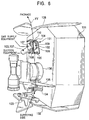
- the hairiness suppressing device 1 shown in Figures 1 and 2 is provided in a tenser box 31 of the automatic winder.
- the tenser box 31 is configured as a unit comprising a lower yarn detector 32 using a photoelectric sensor, a hairiness suppressing device 1, a gate tenser 33, a waxing device 34, and a suction nozzle 35 arranged in the order from a supplying side (an upstream side) for a spun yarn (a yarn formed by twisting fibers) that runs to a package.
- the hairiness suppressing device 1 comprises a central nozzle body 21, a blowout hole 22 disposed along a yarn path above the nozzle body 21, a suction nozzle 23 at the side of the blowout hole 22, the first yarn guide plate 24 and the second yarn guide plate 25 located above and below the central nozzle body 21, the first yarn presser guide 27 and the second yarn presser guide 28 provided at the top and bottom of a swiveling body, and a cover member 29.
- the integral nozzle body 21 is obtained by fitting a ceramics element 6 in a nozzle holder 7 having a recess cross section and tightening the element using bolts (not shown in the drawings).
- the element 6 has formed therein a long yarn passage 8 penetrating the element at its axis (a) and having a circular cross section and has formed therein an opening 9 extending in the direction of the axis (a) of the yarn passage 8.
- a yarn is inserted into the opening 9, and the opening 9 comprises a slit section 10 that directly opens into the yarn passage 8 and a fan-shaped enlarged section 11 that connects to the slit section 10.
- a yarn is introduced into the yarn passage 8 through the fan-shaped enlarged section 11 and the slit section 10.
- the slit section 10 is formed parallel with and eccentrically to the axis (a) of the yarn passage 8 and in a tangential direction of the yarn passage 8.
- the slit section 10 is open over the length of the axis (a) of the yarn passage
- a plurality of jet holes 12, 13 that jet a gas such as air, humidified air, or steam are formed in the yarn passage 8, as shown in Figure 4.
- Each of the jet holes 12, 13 is formed around the yarn passage 8 except for the opening 9 and opens into the yarn passage 8 horizontally from the tangential direction of the inner circumference of the yarn passage 8.
- Each jet hole 12, 13 is in communication with a port 15 via a header section 14.
- the port section 15 is connected to air supply equipment (not shown in the drawings) via each pipe (not shown in the drawings).
- the first and second guide plates 24, 25 shown in Figure 1 guide a lower yarn carried by a lower yarn suction pipe (not shown in the drawings) to the yarn insertion opening 9 in the nozzle body 21, and are formed to have a right and a left receiving sections leading to a central guide port.
- the first and second presser guides 27, 28 shown in Figure 1 are integrated with the top and bottom of the swiveling body 26 and can be swiveled around a support shaft (not shown in the drawings) provided behind the swiveling body 26.
- the first and second yarn presser guides 27, 28 are swivellably moved so as to advance and withdraw between an advanced position, which is shown by the solid line, and a withdrawn position, which is shown by the chain double-dashed line.
- the tips of the first and second yam presser guides 27, 28 cover the yarn passage 8.
- nodes of yarns are formed at the top and bottom of the yarn passage 8 to ensure that the yarn is ballooned in the yarn passage 8.
- the cover member 29 shown in Figure 1 is structured to hold a wedge member 30 in a holder section 26b so as to oscillate, wherein the holder section 26b is located at the tip of an arm section 26a extending from the center of the swiveling body 26.
- the wedge member 30 has a tip shape that is tightly fitted in the fan-shaped enlarged section 11, as shown in Figure 3.
- a vertical shafts 30a of the wedge meter 30 engages with long holes 26c in the bolder section 26b so that the wedge member 30 can oscillate in the direction shown by arrow (b) and can move laterally.
- the lower yarn detector 32 in Figure 1 checks whether a lower yarn (a yarn of supply side) is held. Without a lower yarn, the yarn cannot be spliced.
- the gate tenser 33 has a movable comb edge 33b that can open and close a fixed comb edge 33a and can be switched between a meshing position at which the comb edges 33a, 33b mesh with each other and an open position at which a yarn can be introduced. While the comb edges 33a, 33b are closed, a zigzag yarn path is formed to apply a predetermined tension to a running yarn.
- the waxing device 34 abuts a running yarn Y on an end face of a roll 34a made of wax in order to apply wax to the yarn.
- the roll 34a is rotated at a low speed and an arm 34b applies a predetermined pressure to a yarn.
- the arm 34b, the movable comb edge 33b, and the swiveling body 26 are concurrently opened and closed by a common drive section 17.
- the suction nozzle 35 which is shaped like a nozzle, sucks and captures the end of an extra cut yarn, and is connected to suction equipment (not shown in the drawings).
- the drive device 17 directs the roll 34a of the waxing device 34 toward the yarn path, closes the movable comb edge 33b of the gate tenser 33, and moves the swiveling body 26 to an advanced position. Then, as shown by the solid line in Figure 4, the upper and lower yarn presser guides 27, 28 advance to the position at which they cover the yarn passage 8, and the wedge member 30 of the cover member 29 is also tightly fitted in the fan-shaped enlarged section 11 of the yarn introducing opening 9. In these conditions, a gas is jetted into the yarn passage 8 from the jet holes 12, 13, and the yarn is wound to run. Then, a whirling current is formed in the yarn passage 8 to balloon the yarn using as nodes the yarn presser guides 27, 28 of the yarn passage 8.
- hairiness suppressing processing is executed that entangles hairinesses protruding fibers, with the fibers for suppressing or that uses the ballooning to flying away long hairinesses by force. Hairinesses and fluffs contained in an air current blown out from the yarn path are sucked by the suction nozzle 23.
- the yarn introducing opening 9 is tightly closed by a cover member 29, so no whirling current flows from the side of the yarn passage 8.
- the yarn is perfectly ballooned in the yarn passage 8 to allow the hairiness suppressing processing to be effectively executed.
- the amount of compressed air required to form a whirling current is reduced to minimize energy losses.
- steam can be used as a gas for ballooning the yarn Y formed by twisting fibers.
- both the yarn Y passing through the yarn passage 8 and the inner circumferential surface of the yarn passage 8 can be heated using steam.
- the steam also enables the hairinesses on the yarn Y to be softened.
- the yarn Y which is ballooned in such a way as to slide through the inner circumferential surface of the yarn passage 8, enables its hairinesses that have been softened by twisting to be effectively entangled with and caught in the fibers, while due to contact with the inner circumferential surface of the yarn passage 8, the yarn Y is heat-set as if it was ironed, thereby maintaining a form with a reduced number of hairinesses.
- An automatic winder W comprises a large number of winding units installed in a line, and each winding unit U comprises the tenser box 31 in Figure 1.
- Each winding unit U comprises a mechanism for passing the yarn Y unwound from a supplying bobbin E supplied at a predetermined position, through a balloon breaker 39, the hairiness suppressing device 1, tenser 33, waxing device 34, and suction nozzle 35 of the tenser box 31, and a slab catcher 48 that detects a defect in the yarn Y, before winding the yarn around a package P rotated by a traverse drum 41.
- 42 is a yarn splicing device
- 44 is a suction (upper yarn suction pipe) mouth that guides the yarn end on the package P side to the yarn splicing device 42
- 43 is a relay (lower yarn suction pipe) pipe that guides the lower yarn of the supplying bobbin E side to the yarn splicing device 42.
- the yarn Y is unwound from the supplying bobbin E and is subjected to the hairiness suppressing processing that uses a whirling current to balloon the yarn while it is passing through the hairiness suppressing device. If any defect is found in the yarn being wound around the package P, the yarn must be spliced. In this case, the jetting of a gas from the nozzle body 21 of the hairiness suppressing device 1 is stopped, and an extra yarn end is sucked and captured by the suction nozzle 35.
- the relay pipe 43 is swiveled to the neighborhood of the balloon breaker 39 to suck the lower yarn captured by a means (not shown in the drawings) and then to guide it to the yarn splicing device 42.
- each equipment of the tenser box 31 is open and the yarn Y runs along the illustrated yarn path.
- the suction mouth 44 sucks the yarn end on the package P side to guide it to the yarn splicing device 42, which then splices the yarn.
- each equipment of the tenser box 31 is activated to start winding the yarn Y while carrying out the hairiness suppressing processing.
- a hairiness suppressing device for achieving the second object is described below with reference to the drawings.
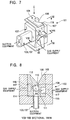
- a hairiness suppressing device 101 which is shown in Figure 6, is provided in a tenser box 131 of a winder (for example, an automatic winder).
- the tenser box 131 comprises a guide plate 132, a cutter 133, a gate feeler 134, a guide plate 135, a disc tenser 136, a yarn trap 137, and a guide plate 138 arranged in the order from a supplying side for a yarn YY (for example, a spun yarn comprising a collection of fibers) that runs to a package.
- the hairiness suppressing device 101 is provided in the yarn trap 137 in a yarn path.
- the yarn trap 137 which is shaped like a nozzle, sucks and captures the end of a cut yarn on the supplying side, and is connected to suction equipment (not shown in the drawings).
- the hairiness suppressing device 101 comprises a whirling air current jet nozzle 102 (a jet nozzle means) for suppressing the generation of the hairinesses of the yarn YY, a suction nozzle 103 (a suction means) that sucks and removes dust or fluff from the yarn YY, and two yarn regulating plates 104, 105 that regulate the yarn YY.
- the yarn trap 137 of the tenser box 131 is also used as the suction means (the suction nozzle 103).
- the integral whirling air current jet nozzle 102 is obtained by fitting a ceramics element 106 in a nozzle holder 107 having a recess cross section and tightening the element using bolts.
- the element 106 has formed therein a circular yarn passage 108 (a yarn passage hole) penetrating the element at its axis aa, and the yarn YY is introduced into the yarn passage 108 through a yarn introducing port 109 having a triangular opening and through a slit 110.
- the yarn introducing port 109 is formed parallel with and eccentrically to the axis aa of the yarn passage 108, and together with the slit 110, penetrates the element 106 in the axial direction (see Figures 8 and 9).
- the yarn passage 108 has formed therein a plurality of jet holes 111 to 113 that jet a gas (air, humidified air, or steam) and a long suction hole 114 for sucking the inside of the yarn passage 108.
- Each of the jet holes 111 to 113 is formed around the yarn passage 108 except for the yarn introducing port 109 and a portion opposed to the yarn introducing port 109, and opens into the yarn passage 108 horizontally from the tangential direction of the inner circumference of the yarn passage 108.
- the jet holes 111 and 113 are located on one side of the yarn passage 108 and formed at each axial end, and are in communication with each other in a jet space 115.
- the remaining jet hole 112 is located on the other side of the yarn passage 108 and formed in the axial center of the element 106, and is in communication with a jet space 116.
- the jet spaces 115, 116 are each in communication with gas supply equipment (not shown in the drawings) via each jet port 117 of the nozzle holder 107 and each pipe connected to the nozzle holder 107 (see Figures 8 and 9).
- the long suction hole 114 is open in such away as to extend from a side opposed to the yarn introducing port 109 and to intersect the tangential direction of the inner circumference of the yarn passage 108.
- the long suction hole 114 penetrates the element 106 and then penetrates the nozzle holder 107 where the hole 114 has a larger diameter.
- the long suction hole 114 is formed between the jet holes 111 and 113 (see Figures 8 and 9).
- the yarn regulating plates 104, 105 are each provided at each axial end of the element 106.
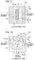
- the yarn regulating plates 104, 105 overlap each other in such a way as to cover each opening in the yarn passage 108 and has a V-shaped guide groove 118 that guides the yarn YY, as shown in Figure 10.
- the yarn regulating plates 104, 105 acts as a guide for ballooning using a whirling air current acting on the yarn YY by regulating the yarn YY introduced into the yarn passage 108 in such a way as to bend it at fulcrums cc, bb of the guide groove 118, as shown in Figure 11.
- the whirling air current jet nozzle 102 is provided in the yarn trap 137 to enable the inside of the yarn passage 108 to be sucked (see Figures 7 to 9).
- a gas from the air supply equipment (not shown in the drawings) is jetted into the yarn passage 108 from each of the jet holes 111 to 113 through each of the jet ports 117 and each of the jet spaces 115, 116. At this point, the gas is jetted from each of the jet holes 111 to 113 in the tangential direction of the inner circumferential surface of the yarn passage 108 to cause a whirling air current in the yarn passage 108 (see Figures 8 and 9).
- the whirling air current occurring in the yarn passage 108 balloons (swivels) the yarn YY in such a way as to slide along the inner circumferential surface of the yarn passage YY using the yarn regulating plates 104, 105 as fulcrums, thereby false-twisting the yarn.
- the yarn YY comes in contact with the guide grooves 118 in the yarn regulating plates 104, 105 while rotating. Accordingly, the hairiness suppressing processing is carried out that entangles hairinesses with the fibers of the yarn for suppressing to restrain further hairinesses (see Figure 11).
- steam can be used as a gas for ballooning (whirling) the yarn YY.
- both the yarn YY passing through the yarn passage 108 and the inner circumferential suface of the yarn passage 108 can be heated using steam.
- the steam also enables the hairinesses (fibers) on the yarn YY to be softened.
- the yarn YY which is ballooned in such a way as to slide through the yarn passage 108, enables its hairinesses that have been softened by false-twisting to be effectively entangled with and caught in the fibers, while due to contact with the inner circumferential surface of the yarn passage 108, the yarn YY is heat-set as if it was ironed, thereby maintaining a form with a reduced number of hairinesses.
- the yarn trap 137 starts suction.
- the yarn trap 137 provides such a suction force as not disturb the whirling air current in the yarn passage 108 or not suck the ballooned (whirled) yarn YY.
- the yarn trap 137 can suck and remove dust or fluff leaving the yarn YY due to the whirling air current occurring in the yarn passage 108 and the ballooning of the yarn YY or can directly suck and remove dust or fluff from the yarn YY passing through the long suction hole 114 (see Figure 11).
- the suction means may be formed, for example, between the cutter 133 and the gate feeler 134.
- the long suction hole 114 in the whirling air current jet nozzle 102 must be directly connected to the suction equipment via piping.
- the hairiness suppressing device 101 in Figures 6 to 11 has been shown in conjunction with the long suction hole 114 intersecting the tangential direction of the inner circumferential surface of the yarn passage 108
- the long suction hole 114 may be formed in the tangential direction of the inner circumferential surface of the yarn passage 108 so as to open into the yarn passage 108, as shown in Figure 12.
- the long suction hole 114 opens into the yarn passage 108 in such a way as to be opposed to a whirling direction AA of the whirling air current.
- this configuration can efficiently suck and reliably remove dust or fluff leaving the yarn and flowing along the inner circumferential surface of the yarn passage 108 due to the swiveling force (centrifugal force) of the whirling air current or can directly suck and remove dust or fluff from the yarn YY in the same manner, without disturbing the whirling air current (the ballooning of the yarn YY) in the yarn passage 108.
- An automatic winder WW which is shown in Figure 13, comprises a large number of winding units installed in a line, and each winding unit 125 comprises a tenser box 131 in Figure 6 (including the hairiness suppressing device 101).
- Each winding unit 125 threads the spun yarn YY unwound from a supplying bobbin EE supplied at a predetermined position, through a balloon breaker 139, a tenser 136 and the hairiness suppressing device 101 of the tenser box 131, and a slab catcher 140 that detects a defect in the yarn YY, and then winding the yarn around a package PP rotated by a traverse drum 141.
- 142 is a yarn splicing device
- 143 is a suction mouth that guides the yarn end on the package PP side to the yarn splicing device 142
- 144 is a relay pipe that guides to the yarn splicing device 142, the yarn end on the supplying bobbin EE sucked and captured by the yarn trap 137.
- each winding unit 125 When the traverse drum 141 of each winding unit 125 is driven to start rewinding (winding) the yarn YY, the yarn YY is unwound from the supplying bobbin EE and subjected to the hairiness suppressing processing that uses a whirling current from the whirling air current jet nozzle 102 to balloon and false-twist the yarn while it is passing through the hairiness suppressing device 101.
- the yarn trap 137 can suck and remove dust or fluff leaving the yarn Y, thereby enabling the yarn to be subjected to the hairiness suppressing processing in a clean state.
- this operation is significantly effective on a spun yarn comprising a collection of fibers, enabling reliable hairiness suppressing processing and the reliable removal of fluff or dust from the yarn.
- the yarn YY must be spliced.
- the jetting of a gas from the whirling air current jet nozzle 102 of the hairiness suppressing device 101 is stopped, and an extra yarn end on the supplying bobbin EE side is sucked and captured by the yarn trap 137.
- the relay pipe 144 is swiveled to the neighborhood of the balloon breaker 139 to suck the end of the yarn captured by the yarn trap 137 and then to guide it to the yarn splicing device 142.
- the yarn YY is threaded through each of the members 132 to 135 and tenser 136 of the tenser box 131 and then threaded through the yarn passage 108 of the hairiness suppressing device 101 via the yarn introducing port 109 and the slit 110. Subsequently, the suction mouth 143 sucks the yarn end on the package PP side to guide it to the yarn splicing device 142, which then splices the yarn YY.
- the yarn trap 137 can also be used as the suction means for the hairiness suppressing device 101 without hindering the conventional functions of the yarn trap 137.
- the hairiness suppressing device 101 may be applied to the automatic winder WW.
- a winder such as a doubling and twisting machine or a warper.
- 201 is a supplying package (supplying bobbin), and a spun yarn y rewound from a supplying package 201 is wound around a winding package (not shown in the drawings).
- 202a, 202b are yarn guides approximately Y-shaped in a top view, placed above the supplying package 201, and spaced at a predetermined interval.
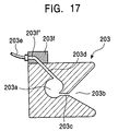
- the whirling air current generation member 203 is a whirling air current generation member shaped approximately line a prism, and disposed between the yarn guides 202a, 202b.
- the whirling air current generation member 203 has a vertical hole 203a is formed at its center, and has on one side, a recess section 203b shaped like a triangle in a top view and enlarging toward the side wall.
- the whirling air current generation member 203 also has formed therein a slit 203c that connects the triangular recess section 203b and the vertical hole 203a together and through which a yarn can be inserted to pass.
- the vertical hole 203a has machined approximately at its center, an air jet hole 203d opening in a tangential direction of the inner circumferential surface of the vertical hole 203a.
- Figure 17 shows an example in which one air jet hole 203d is machined, but a plurality of air jet holes 203d may be provided in the tangential direction of the inner circumferential surface of the vertical hole 203a.
- 203e is a pipe attached to one side surface of the whirling air current generation meter 203 to supply compressed air to the air jet hole 203d via a block 203f having a transparent hole 203f' in communication with the air jet hole 203d.
- the fixed guide member 204 is a fixed guide member mounted on one side surface of the whirling air current generation member 203.
- the fixed guide member 204 comprises a vertical section 204c mounted on the one side surface of the whirling air current generation member 203 and horizontal sections 204a, 204b extending horizontally front the upper and lower ends of the vertical wall 204c.
- Recess sections 204a', 204b' each shaped like a triangle in a top view are formed in the horizontal sections 204a, 204b in the same orientation as the recess section 203b.
- the fixed guide member 204 is mounted on the whirling air current generation member 203 so that the bottom 204a'', 204b'' of the triangular recess section 204a', 204b' of the fixed guide member 204 is located approximately at the center of the vertical hole 203a in the whirling air current generation member 203.
- movable guide member 205 is a movable guide member having an approximate turned-sideways U-shape in a front view and disposed outside the fixed guide member 204, and horizontal plates 205b attached to a vertical section 205a of the movable guide member 205 are fitted on a vertical rod 207 rotatably supported by support plates 206a, 206b attached to an appropriate frame.
- Horizontal sections 205c are formed to extend horizontally front the upper and lower ends of the vertical section 205a.
- 208 is a gate tension member provided as an example of a tension applying device disposed between the lower yarn guide 202a and the movable guide member 205.
- a fixed section 208a of the gate tension member 208 is attached to an appropriate frame 208b, and a movable section 208c of the gate tension member 208 is attached to the vertical rod 207.
- 210 is a yarn trap comprising a suction pipe.
- the movable guide meter 205 or the movable section 208c of the gate tension member 208 is rotationally moved away from the fixed guide member 204 or the fixed section 208a of the gate tension meter 208 around the vertical rod 207 against the urging force of the coil spring 209.
- the movable guide member 205 is withdrawn so as not to obstruct the introduction of the yarn y into the vertical hole 203a in the whirling air current generation member 203 and the recess sections 204a', 204b' in the fixed guide member 204, while the movable section 208c is separated from the fixed section 208a of the gate tension meter 208 so that the yarn y can abut on the fixed section 208a.
- the yarn y drawn upward from the supplying package 201 is placed on the fixed section 208a of the gate tension meter 208 and then in the vertical hole 203a in the whirling air current generation meter 203 through its slit 303c.
- the urging force of the coil spring 209 rotationally moves the withdrawn movable guide member 205 toward the fixed guide meter 204, and the fixed guide member 204 and the movable guide member 205 sandwiches the yarn y so as to allow the yarn y introduced into the recess sections 204a', 204b' of the fixed guide member 204 to be placed at the bottom 204a'', 204b'' of the recess sections 204a', 204b' located approximately at the center of the vertical hole 203a in the whirling air current generation member 203.
- the movable section 208c of the gate tension member 208 presses the yarn y located at the fixed section 208a so that the gate tension member 208 applies an appropriate tension to the yarn y.
- the yarn y drawn upward from the supplying package 201 is wound around a winding package (not shown in the drawings) via the lower yarn guide 202a, the gate tension member 208, the whirling air current generation member 203 with the fixed guide member 204 and movable guide member 205 disposed above and below it, and the upper yarn guide 202b.
- the sandwiching force applied to the yarn y by the fixed guide member 204 and the movable guide member 205 naturally has such a magnitude as not obstruct the running of the yarn y or damage the yarn y.
- the yarn y sandwiched between the fixed guide meter 204 and the movable guide member 205 above and below the whirling air current generation member 203 so as to be located approximately at the center of the vertical hole 203a in the whirling air current generation member 203 is then ballooned by a whirling air current in the vertical hole 203a in the whirling air current generation member 203, between the points at which it is sandwiched between the fixed guide member 204 and the movable guide member 205.
- the balloon formed by the whirling air current is large because the points at which the yarn y is sandwiched between the fixed guide member 204 and the movable guide member 205 are located approximately at the center of the vertical hole 203a in the whirling air current generation member 203.
- hairiness suppressing processing is carried out that uses the whirling air current and the ballooning to effectively remove fluffs or dust simply adhering to the yarn y and that suppresses hairinesses protruding from the surface of the yarn y, to the surface of the yarn y in order to reduce the hairinesses.
- the yarn y has a weak portion and when it is swung by the ballooning, it is cut at the weak portion.
- the yarn y cut at the weak portion is then spliced by a splicing device such as a knotter or a splicer (not shown in the drawings).
- a splicing device such as a knotter or a splicer (not shown in the drawings).
- the means for holding the yarn y approximately at the center of the vertical hole 203a in the whirling air current generation meter 203 is composed of the fixed guide member 204 disposed at the inlet and outlet gates of the whirling air current generation member 203 and the movable guide member 205 that is urged toward the fixed guide member 204.
- a yarn guide such as an eyelet guide or a wire guide that holds the yarn y approximately at the center of the vertical hole 203a in the whirling air current generation member 203 may be disposed at the inlet and outlet gates of the whirling air current generation member 203 to hold the yarn y approximately at the center of the vertical hole 203a in the whirling air current generation member 203.
- the means for holding the yarn y approximately at the center of the vertical hole 203a in the whirling air current generation member 203 is composed of the fixed guide member 204 disposed at the inlet and outlet gates of the whirling air current generation member 203 and the movable guide member 205 that is urged toward the fixed guide member 205, the movable guide member 205 can be rotationally moved away front the fixed guide member 204 to withdraw so as not to obstruct the introduction of the yarn y into the vertical hole 203a in the whirling air current generation meter 203, thereby facilitating the insertion of the yarn y into the vertical hole 203a of the whirling air current generation member 203.
- the vertical rod 207 can be rotated to rotationally move the movable guide member 205 and the movable section 208c of the gate tension member 208 at the same time.
- This configuration can promptly and easily finish setting the yarn y approximately at the center of the vertical hole 203a in the whirling air current generation member 203 and sandwiching the yarn y between the components of the gate tension member 208.
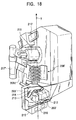
- a whirling air current generation member 203' similar to the whirling air current generation member 203 is placed below a gate tension meter 208' similar to the gate tension member 208.
- 211 is a cylindrical wax member attached to a vertical rod 207' similar to the vertical rod 207 to apply wax to the yarn y.
- 205' is a movable guide member similar to the movable guide member 205, 212 is a suction nozzle for sucking hairinesses severed by ballooning the yarn y in order to prevent hairinesses from splashing, and 213 is an air blast nozzle for cleaning that jets air.
- the positions at which the whirling air current generation member 203 and the movable guide member 205 are placed are not limited to the above embodiment.
- Figure 19 is a perspective view of essential parts of an automatic winder 301 in which a hairiness suppressing device 310 is installed.
- Figure 20 is a perspective view showing that the hairiness suppressing device 310 in Figure 19 is decomposed.
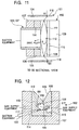
- Figure 21 is a sectional view of nozzle means 311 of the hairiness suppressing device 310.
- Figure 22 is a top view of the hairiness suppressing device 310.
- the hairiness suppressing device 310 comprises central nozzle means 311, a twisting stop means 312 provided at the inlet side of the nozzle means 311, and twisting stop means 313 provided at the outlet side of the nozzle means 311.
- the nozzle means 311 comprises a body 315 made of ceramics and a holder 316 in which the body 315 is fitted.
- the body 315 has a yam passage 317 formed as a through-hole having a circular cross section, and a gas-jetting hole 318 that opens approximately in the middle of the yarn passage in the direction of a central axis 3171 and that extends in a tangential direction of the circular cross section of the yarn passage 317.
- Two or more gas-jetting holes 318 are preferably provided as shown in the drawings.
- Compressed air is normally jetted from the gas-jetting hole 318.
- the yarn passage 317 has a slit like opening 320 extending in a direction along the central axis 3171 thereof. Since the opening 320 is open in a tangential direction reverse to the direction of the whirling current 319, the spun yarn Y ballooned by the whirling current 319 is prevented from jumping out from the opening 320. In addition, because of an inclined surface 3201 formed after the opening 320 in such a way as to extend like a fan, the yarn Y, which has passed the inclined surface 3201, is reliably inserted into the yarn passage 317 through the opening 320. In addition, as clearly shown in Figure 21, a gas passage 321 reaching the gas-jetting hole 318 is formed in the body 315 and the holder 316 as appropriate.
- the twisting stop means 312 at the inlet side comprises a first guide member 325 and a second guide member 326 that are provided close to the inlet of the yarn passage 317.
- the twisting stop means 313 at the outlet side comprises a first guide member 327 and a second guide member 328 that are provided close to the outlet of the yarn passage 317.
- Part of the first guide members 325, 327 and second guide meters 326, 328 that is in contact with the yarn Y is formed of ceramics.
- the first guide meters 325, 327 are disposed closer to the inlet or outlet of the yarn passage 317 and are fixed to predetermined positions above or below the holder 317 by means of bent sections 3252, 3272.
- the first guide meters 325, 327 have V-shaped recess sections 3251, 3271, respectively, that open toward the opening 320. As shown in Figure 22, the bottom of the recess sections 3251, 3271 is located near the central axis 3171 of (in the center of ) the yarn passage 317.
- the second guide meters 326, 328 are plate, and are placed farther from the inlet or outlet of the yarn passage 317 and at a predetermined distance from the first guide meters 325, 327, respectively. As shown in Figure 19, the second guide meters 326, 328 are integrally fixed to a lever 329. The lever 329 can be swivellably moved around a shaft 330. When the second guide members 326, 328 are placed at operating operations as shown in Figure 20, the yarn Y is held at the bottom of the recess sections 3251, 3271 of the first guide members 325, 327 while being bent in such a way to leave the central axis 3171.
- Figure 23 is a side sectional view of the hairiness suppressing device 310 in Figure 19 in which the second guide eaters 326, 328 are at the withdrawal positions.
- Figure 24 is a side sectional view of the hairiness suppressing device 310 in Figure 19 in which the second guide members 326, 328 are at the operating positions.
- the second guide members 326, 328 are located at the illustrated operating positions, while a gas is simultaneously jetted from the gas-jetting hole 318 to generate a whirling current in the yarn passage 317. Subsequently, the yarn Y is run from bottom to top as shown by the arrow in the drawing. Using the bottom of the recess sections 3251, 3271 of the first guide members 325, 327 as nodes, the yarn Y starts to be ballooned as shown in the drawing.
- the yarn Y Since the second guide members 326, 328 bend the yarn Y in such a direction as to further drive it to the bottom of the recess sections 3251, 3271, the yarn Y is held at the bottom of the recess sections 3251, 3271, while the first guide meters 325, 327 and the second guide members 326, 328 bend the yarn Y to almost stop propagation of twisting applied to the yarn Y within the yarn passage 317.
- the spun yarn Y is held at the center of the yarn passage 317, so it is ballooned uniformly and stably. This ballooning causes the spun yarn Y to be twisted.
- the spun yarn Y is formed by twisting short fibers and is originally twisted, for example, in Z directions, as shown in the drawing.
- the direction of the whirling current 319 is preferably such that the yarn Y is additionally twisted at the outlet side of the yarn passage 317 while being untwisted at the inlet side thereof. Due to twisting stop carried out by the guide members 325, 326, 327, 328 at the inlet and outlet limits, false-twisting based on the untwisted and additionally twisted parts of the yarn Y occurs only between the guide members 325 and 327.
- the degree of twisting stop carried out by the first guide members 325, 327 and the second guide members 326, 328 can be adjusted based on the push-in amount for the second guide members 325, 327.
- an appropriate push-in amount for stopping propagation of twisting to the yarn Y can be set by changing the length of a stopper 391 mounted on the lever 329.
- twisting stop means 312 is provided at the inlet side of the nozzle means 311 without the twisting stop means 313 at the outlet side or the twisting stop means 313 is provided at the outlet side of the nozzle means 311 without the twisting stop means 312 at the inlet side, twisting applied to the yarn Y by the whirling current is substantially stopped from propagating beyond at least either the inlet or outlet.
- the yarn Y is twisted or untwisted within a short section, while hairinesses are effectively caught in the fibers or unwanted fibers are effectively flung away.
- the twisting stop means 313 provided at the outlet side of the nozzle means 311 allows hairinesses to be caught in the yarn Y after unwanted fibers have been flung away.
- the twisting stop means 312, 313 are provided at the inlet and outlet of the nozzle means 311.
- the whirling current may be formed such that the additionally twisted part is formed at the inlet side of the yarn passage 317, while the untwisted part is formed at the outlet side of the yarn passage 317. More preferably, however, the additionally twisted part is provided at the outlet side of the yarn passage 317 because this configuration allows hairinesses to be caught in the yarn after unwanted fibers have been flung away, thereby enabling reliable hairiness suppression.
- the yarn Y may be held at a position eccentric to the yarn passage 317.
- the yarn Y is ballooned symmetrically due to the nodes along the central axis, resulting in stable ballooning.
- twisting stop means for the yarn Y.
- Means may be used that abuts two plates on each other to sandwich the yarn Y therebetween, or gate means may be used that pushes one plate in between two plates to bend the yarn Y in a zigzag manner.
- the twisting stop means comprising the two guide members 325, 326 or 327, 328 is advantageous in that twisting can be stopped while maintaining the tension of the yarn Y at a low level, thereby reducing the possibility of yarn breakage.
- the second guide members 326, 328 are prevented from obstructing introduction of the yarn Y, which has passed through the opening 320 of the yarn passage 317, thereby enabling the first guide members 325, 327 to reliably hold the yarn Y.
- the automatic winder 301 comprises a large number of winding units 302 installed in a line.
- Each of the winding units 302 is configured to wind the yarn unwound from the supplying bobbin supplied at a predetermined position, into a package 304 rotated by a traverse drum 356 after passing the yarn through a balloon breaker 351, a tenser 352 for applying yarn tension, the hairiness suppressing device 310, a suction nozzle 353 for holding a supplying bobbin side yarn end (a lower end) upon yarn breakage, a slab catcher 354 for detecting defective parts of the yarn Y, and a yarn splicing device 355.
- a suction mouth (upper yarn suction pipe) 357 is provided above the yarn splicing device 355 for guiding a package 304 side yarn end to the yarn splicing device 355, while a relay pipe (lower yarn suction pipe) 358 is provided below the yarn splicing device 355 for guiding the lower end located at the supplying bobbin 303 side to the yarn splicing device 355.
- the tenser 352 As shown in Figure 19, the tenser 352, the hairiness suppressing device 310, and the suction nozzle 359 are mounted on a side of a tenser box 359.
- the tenser 352 is of a gate type that engagingly places a movable coat edge 3522 relative to a fixed coat edge 3521.
- the movable coat edge 3522 is attached to the tip of an arm 3529, which is attached to a shaft 360 interlocked with the shaft 330.
- the second guide members 326, 328 of the hairiness suppressing device 310 and the comb edge 3522 of the tenser 3522 are opened and closed at the same time.
- the tenser 352 of the tenser box 359 and the hairiness suppressing device 310 are open, so the yarn Y runs along the illustrated yarn path.
- the suction mouth 357 sucks the package 304 side yarn end to guide it to the yarn splicing device 355, which then splices the yarn.
- each component of the tenser box 359 is actuated to start winding the yarn Y while subjecting it to hairiness suppressing processing.
- the hairiness suppressing device 310 suppresses hairinesses that may occur during unwinding of the yarn Y from the supplying bobbin 303 or during application of tension by the tensor 352, thereby enabling the yarn Y to be rewound while suppressing hairinesses.
- a waxing device for waxing the yarn may be installed at the downstream side of (above) the hairiness suppressing device 310.
- the installation of the waxing device enables the hairiness suppressing device 310 to be disposed at the upstream side of (below) the tenser 352 if no space is available for the hairiness suppressing device 310 to be placed. More preferably, however, the hairiness suppressing device 310 is provided at the downstream side of the tenser 325 because this configuration suppresses hairinesses that may be caused by the tenser 352.
- humidified air containing vapors or water droplets can be used as a gas for generating a whirling current to twist the spun yarn Y formed by twisting fibers.
- the use of vapors enables heating of the yarn Y passing through the yarn passage 317 and of the inner periphery surface of the yarn passage 317, and the contact with the inner periphery surface of the yarn passage 317 causes the yarn to be heated as if it is ironed, thereby enabling heat set while maintaining a reduced amount of hairinesses.
- hairinesses on the yarn Y can be softened.
- hairinesses softened by false-twisting based on untwisting and additional twisting can be entangled with and caught in the yarn Y twisted through the yarn passage 317.
- dry heated air can be used as a gas for causing a whirling current.
- the present invention has the following effects.
- the cover member closes the yarn inserting opening to prevent the whirling flow from leaking from the yarn inserting opening.
- This configuration can improve the hairiness suppressing performance based on the ballooning of the yarn and reduce energy losses caused by the leakage of the whirling current.
- the cover member is provided for the yarn presser guide, the yarn presser guide is swivellably moved to allow the cover meter to open or close the yarn inserting opening, thereby eliminating the needs for a separate drive mechanism for opening and closing the cover member.
- the yarn can be perfectly ballooned in the yarn passage.
- the hairiness suppressing device for achieving the second object can use the jet nozzle means to balloon (whirl) and false-twist a yarn in order to execute the hairiness suppressing processing that entangles hairinesses with the fibers for suppressing.
- the sucking means to suck the inside of the yarn passage simultaneously with this hairiness suppressing processing, this configuration can suck and remove dust or fluff leaving the yarn due to a whirling air flow or the ballooning (whirling) of the yarn.
- the hairiness suppressing processing can be executed in a clean state to reduce the amount of dust or fluff caught in the fibers, thereby improving the quality of packages.
- the yarn trap of the winder is also used as the suction means, the device existing in the winder can be used to suck and remove dust or fluff.
- the present invention can be inexpensively placed in the winder without the need to provide a separate suction means.
- the suction means carries out suction in the tangential direction of the whirling air current, dust or fluff can be efficiently sucked and reliably removed from the yarn passage without disturbing the whirling air current (ballooning of the yarn) in the yarn passage.
- the present invention has the following effects.
- this configuration can prevent a yarn cut at a weak portion leading to the degradation of the working efficiency of a subsequent step such as a warping step. As a result, the working efficiency of the subsequent step such as a warping step is improved.
- the simple configuration including the whirling air current generation member for generating a whirling air current and the means for holding the yarn approximately at the center of the vertical hole in the whirling air current generation meter at the gate of the whirling air current generation meter, hairinesses protruding from the surface of the yarn can be effectively restrained and a weak portion can be cut and removed.
- the means for holding the yarn approximately at the center of the vertical hole in the whirling air current generation member is composed of the fixed guide member disposed at the gate of the whirling air current generation member and the movable guide member that is urged toward the fixed guide member.
- the movable guide member can be rotationally moved away from the fixed guide member to withdraw so as not to obstruct the introduction of the yarn into the vertical hole in the whirling air current generation member, thereby facilitating the insertion of the yarn into the vertical hole in the whirling air current generation member.
- the twisting stop means substantially stops twisting applied to the yarn by the whirling current from propagating to the upstream and downstream sides of the yarn passage, thereby allowing yarn false-twisting based on untwisting and additional twisting to be carried out within a short section.
- hairinesses are effectively entangled with and caught in the fibers, or untwisting or ballooning during untwisting causes unwanted fibers to be effectively flung away, thereby suppressing hairinesses that any occur during a yarn rewinding step.
Abstract
Description
- The present invention relates to a hairiness suppressing device provided in a yarn path of an automatic winder that unwinds a spun yarn on a supplying side to wind it around a package.
- For example, supplying bobbins around which spun yarns produced by means of ring spinning have been wound are transferred to an automatic winder, where the yarns from a large number of supplying bobbins are spliced together while defects in the yarns are being eliminated. Thus, the yarns are rewound into corn-shaped or cheese-shaped packages.
- This rewinding executed by the automatic winder comprises a step for using a tenser to apply tension to the yarn rewound from the supplying bobbin while using a large number of yarn guide to guide the yarns to form them into a package. Thus, each time a yarn formed by twisting short fibers passes through the tenser or the yarn guide, the yarn, on which hairinesses have been present since the yarn was located on a supplying bobbin, tends to be subjected to friction and to have more hairinesses after the rewinding.
- Thus, in the rewinding step in the conventional automatic winder, a hairiness suppressing device is provided in a yarn path to suppress hairinesses. This hairiness suppressing device carries out hairiness suppressing processing by jetting a gas such as air into a yarn passage through which the yarn passes in order to cause a whirling current, thereby ballooning the yarn to entangle hairinesses with the fibers for suppressing, or by using the ballooning to fly away the hairiness by force.
- The hairiness suppressing device is structured to have a yarn insertion opening that extends and opens in an axial direction of the yarn passage so that a yarn is inserted into the yarn passage through this yarn insertion opening.
- The prior art, however, has the following problems.
- First, according to the conventional hairiness suppressing device, the yarn insertion opening is formed in the yarn passage in which a whirling current of a gas acts on a yarn, so the whirling current may leak from the yarn insertion opening and the yarn ballooning caused by the whirling current may become insufficient to preclude the ballooning-induced hairiness suppressing effect from being obtained as expected. A hairiness suppressing device that is divided into two so as to be opened and closed has been provided. Since, however, the abutting surfaces of these two parts cannot be aligned easily, it is difficult to perfectly prevent the whirling current from leaking from the side of the yarn passage.
- Second, the conventional hairiness suppressing device can suppress hairinesses by ballooning the yarn, but dust or fluff adhering to the yarn may be entangled with and caught in the fibers together with the hairinesses. This entanglement of dust or fluff with the fibers degrades the quality of packages.
- Then, there is a third following problem. A yarn rewinding device (an automatic winder) has disposed therein a slab catcher or a yarn clearer that can detect and remove defects in the yarn such as slabs, or those portions that have a thickness smaller or larger than a predetermined value. These devices, however, cannot detect those portions that have been weakened due to insufficient twisting, despite the lack of appearance defects. With a yarn that has a weak portion and that has not been detected by the slab catcher or yarn clearer, this portion may be cut during a subsequent step such as a warping step to reduce the working efficiency of this step.
- In addition, although a known yarn processing method and device suppresses hairinesses by passing a spun yarn through a whirling air current, it cannot hold the yarn at the center of a gate to a whirling air current generation member that generates a whirling air current. Consequently, the yarn is insufficiently ballooned in the whirling air current generation member to prevent the desired suppression on hairinesses.
- Furthermore, a fourth problem is that the conventional hairiness suppressing device cannot provide the effect of suppressing hairiness of a spun yarn as expected even by ballooning the yarn.
- The present invention is provided in view of these problems, and its first object is to provide a hairiness suppressing device for an automatic winder that enables a spun yarn to be perfectly ballooned using a whirling current in a yarn passage.
- The second object of the present invention is to provide a hairiness suppressing device that can suppress dust or fluff adhering to a spun yarn from being entangled with or caught in the fibers while hindering hairiness generation from being formed on a yarn being wound around a package by a winder.
- The third object of the present invention is to solve the problems of the above conventional yarn processing methods and apparatuses in order to provide a spun yarn processing method and device that can remove weak portions of a yarn while simultaneously suppressing hairinesses.
- Furthermore, a fourth object of the present invention is to provide a hairiness suppressing device capable of fully exhibiting a hairiness suppressing function and an automatic winder having integrated therein a mechanism for suppressing hairinesses.
- That is, the present invention has been created to improve spun yarn hairiness suppressing methods and devices.
- To achieve the first object, the hairiness suppressing device set forth in
Claim 1 is a hairiness suppressing device provided in a yarn path of an automatic winder that unwinds a spun yarn on a supplying side to wind it around a package, the device comprising a yarn passage in which a whirling current acts on the yarn and a yarn insertion opening that extends and opens in an axial direction of the yarn passage, characterized in that the device comprises a cover meter that can open and close the yarn insertion opening. - To introduce the yarn into the yarn passage, the cover enter is opened and the yarn is introduced into the yarn passage from the yarn insertion opening. Subsequently, the cover meter is closed to close the yarn insertion opening. Then, the side of the yarn passage in which a whirling current acts on the yarn is closed to prevent the flow from leaking the side, thereby enabling the yarn to be effectively ballooned while reducing energy losses caused by the leakage of the whirling current.
- The aspect of the present invention is a hairiness suppressing device for an automatic winder, wherein the hairiness suppressing device comprises a yarn presser guide that can pivotably move to advance to or withdraw from a gate of the yarn passage and the cover member is provided for the yarn pressure guide.
- The yarn presser guide is provided at each of the upper outlet and lower inlet gates to the yarn passage, and when swiveled to advance, constitutes an upper and a lower nodes for ballooning the yarn. When, however, the yarn is introduced into the yarn passage through the yarn insertion opening, the cover member is swiveled to withdraw so as not to obstruct the introduction. Since the cover meter is provided for the yarn presser guide, the cover member opens and closes the yarn insertion opening in response to the advancement and withdrawal of the yarn presser guide associated with its swiveling movement.
- The aspect of the present invention is a hairiness suppressing device for an automatic winder, wherein the cover member is shaped like a wedge that is fitted in the yarn insertion opening.
- The yarn insertion opening is preferably formed of a slit section located in an axial direction of the yarn passage and a fan-shaped enlarged section that spreads like a fan from the slit section. By tightly fitting the wedge-shaped cover member in the fan-shaped enlarged section, the yarn insertion opening is entirely blocked except for the slit section to substantially prevent leakage from the side of the yarn passage.
- To achieve the second object, the present invention provides a hairiness suppressing device provided in a yarn path of an automatic winder that releases a spun yarn on a supplying side to wind it around a package, characterized in that the device comprises a jet nozzle means having a yarn passage through which the unwound yarn passes and jet holes that open into the injection nozzle means and from which a whirling air current is provided when a gas is jetted into the yarn passage, and suction means provided in the jet nozzle means to suck the inside of the yarn passage.
- Thus, by using a whirling air current in the yarn passage to balloon (whirl) and false-twist a yarn, hairiness suppressing processing can be carried out that entangles hairinesses with the fibers for suppressing. Simultaneously with the hairiness suppressing processing, the inside of the yarn passage can be sucked to suck and remove dust or fluff leaving the yarn due to the whirling air current or the ballooning (whirling) of the yarn. Consequently, the yarn can be subjected to the hairiness suppressing processing in a clean state.
- In addition, if a yarn trap of the winder is also used as the suction means, the device existing in the winder can be used to suck and remove dust or fluff.
- Furthermore, by using the suction means to carry out suction in the tangential direction of a whirling air current, dust or fluffs can be efficiently sucked and reliably removed from the yarn passage without disturbing the whirling air current in the yarn passage.
- According to the present invention, the first feature provided to achieve the third object is as follows; at a gate of a vertical hole of a whirling air current generation member for generating a whirling air current, a spun yarn is held approximately at the center of the vertical hole in the whirling air current generation member, the whirling air current is used to balloon the yarn to suppress hairinesses and to cut a weak portion of the yarn. Second, the device comprises a whirling air current generation member for generating a whirling air current, and a means for holding a spun yarn approximately at the center of a vertical hole in the whirling air current generation member. Third, the means for holding a spun yarn approximately at the center of the vertical hole in the whirling air current generation member comprises a fixed guide member disposed at the gate of the whirling air current generation member and a movable guide member that is urged toward the fixed guide member.
- In order to achieve the fourth object, the present invention provides a hairiness suppressing device provided in a path for a spun yarn formed by twisting fibers, characterized in that the device comprises nozzle means having a yarn passage through which the yarn passes and holes from which a gas is jetted to cause a whirling current in the yarn passage, and twisting stop means provided at at least either the inlet or outlet of the yarn passage to substantially stop twisting applied to the yarn by the whirling current from propagating beyond at least either the inlet or outlet. In addition, the twisting stop means is preferably provided at both the inlet and outlet of the yarn passage to substantially stop twisting applied to the yarn by the whirling current from propagating to the upstream and downstream side of the yarn passage.
- The results of various experiments conducted by the inventors show that insufficient hairiness suppression is achieved by simply ballooning a spun yarn because ballooning may cause twisting applied to the yarn to propagate to the upstream and downstream sides of the yarn passage. The inventors have found that if yarn false-twisting based on untwisting and additional twisting is carried out within a short section, hairinesses can be effectively entangled with and caught in the fibers, or untwisting or ballooning during untwisting effectively flings away unwanted fibers that do not contribute to construction of the yarn. Thus, hairinesses can be effectively suppressed by the twisting stop means for substantially stop twisting applied to the yarn by the whirling current from propagating to at least either the upstream or downstream side of the yarn passage. Preferably, the twisting stop means is provided at both the upstream and downstream sides of the yarn passage. The expression "substantially stop twisting" refers to stopping almost all of the propagation of twisting applied to the yarn by the whirling current, so that the yarn is false-twisted based on untwisting and additional twisting between the twisting stop means.
- In order to carry out effective hairiness suppression, the whirling current is formed in such a direction as to twist the yarn at the outlet side of the yarn passage. This is because a higher hairiness suppressing effect can be obtained by additionally twisting the yarn to catch hairinesses thereon after the yarn has been untwisted to fling away unwanted fibers than by untwisting the yarn after additional twisting. In this case, the twisting stop means is preferably provided at at least the outlet side of the yarn passage. In addition, to stably balloon the yarn to allow the whirling current to reliably twist it, the twisting stop means preferably holds the yarn at the inlet and outlet of the yarn passage so that the yarn is located at the center of the circular cross section of the yarn passage.
- In addition, to stop twisting without subjecting the yarn to a large tension, the twisting stop means preferably comprises two guide members provided at the inlet and outlet of the yarn passage, respectively, so that the two guide members substantially stop propagation of the twisting. Such twisting stop means may comprise first guide members disposed closer to the inlet and outlet of the yarn passage, respectively, to position the yarn approximately at the center of the circular cross section of the yarn passage, and second guide members disposed farther from the inlet and outlet of the yarn passage, respectively, to bend the yarn positioned by the first guides, from the center.
- In addition, to reliably move the yarn into and out from the yarn passage, the yarn passage has an opening into which the yarn is inserted and which extends in a direction along the central axis, the first guide meter is fixed to a predetermined position and has a recess section that opens to the opening side, and the second guide meter can be moved between a position at which the yarn is bent and held in the recess section of the first guide and a position at which the yarn can be introduced into the recess section of the first guide.
- In order to achieve the above object, the present invention provides an automatic winder for unwinding a spun yarn wound around a supplying bobbin to rewind it into a package, characterized in that the winder comprises a yarn passage provided in a yarn guide for the unwound yarn and holes from which a gas is jetted to cause a whirling current in the yarn passage, and twisting stop means provided at at least either the inlet or outlet of the yarn passage to substantially stop twisting applied to the yarn by the whirling current from propagating beyond at least either the inlet or outlet and to hold the yarn at least either the inlet or outlet of the yarn passage so that the yarn is located at the center of the circular cross section of the yarn passage.
- Hairiness suppression is effectively carried out by carrying out spun yarn untwisting and additional twisting within a short section so that hairinesses that may occur during unwinding of the yarn from a supplying bobbin or during passing the yarn through a tensioner are entangled with and caught in the fibers. Alternatively, hairiness suppression is effectively executed by using untwisting or ballooning during untwisting to fling away unwanted fibers that do not contribute to construction of the yarn.
-
- Figure 1 is a perspective view of the integral part of an automatic winder having installed therein a hairiness suppressing device according to a first embodiment.
- Figure 2 is a front view of the integral part of the automatic winder having the hairiness suppressing device installed therein.
- Figure 3 is a perspective view of the integral part of the hairiness suppressing device.
- Figure 4 is a top view of the hairiness suppressing device.
- Figure 5 shows the arrangement of equipment in the automatic winder to which the hairiness suppressing device has been applied.
- Figure 6 is a perspective view showing a tenser box of a winder to which a hairiness suppressing device according to the second embodiment has been applied.
- Figure 7 is a perspective view showing the hairiness suppressing device in Figure 6.
- Figure 8 is a sectional view taken along line XIII-XIII in Figure 7.
- Figure 9 is a sectional view taken along line IX-IX in Figure 7.
- Figure 10 is a different view of Figure 7 as seen from the direction shown by arrow C.
- Figure 11 is a sectional view taken along line XI-XI in Figure 7.
- Figure 12 is a sectional view showing a variation of the hairiness suppressing device according to the second embodiment.
- Figure 13 shows the arrangement of an automatic winder to which the hairiness suppressing device according to the second embodiment has been applied.
- Figure 14 is a partly perspective view of a yarn rewinding device to which a yarn processing method according to the present invention is applied.
- Figure 15 is a front view of Figure 14.
- Figure 16 is a perspective view of a whirling air current generation member and a fixed guide member constituting a yarn processing device, that is a hairiness suppressing device of the third embodiment, according to the present invention.
- Figure 17 is a horizontal sectional view showing the neighborhood of the center of the whirling air current generation member of the yarn processing device according to the present invention.
- Figure 18 is a partly perspective view of a rewinding device according to another embodiment to which the yarn processing method according to the present invention is applied.
- Figure 19 is a perspective view of essential parts of an automatic winder in which a hairiness suppressing device is installed according to a fourth embodiment.
- Figure 20 is a perspective view showing that the hairiness suppressing device in Figure 19 is decomposed.
- Figure 21 is a sectional view of a nozzle means of the hairiness suppressing device in Figure 19.
- Figure 22 is a top view of the hairiness suppressing device in Figure 19.
- Figure 23 is a side sectional view of the hairiness suppressing device in Figure 19, in which second guide meters are located at withdrawal positions.
- Figure 24 is a side sectional view of the hairiness suppressing device in Figure 19, in which second guide meters are located at operating positions.
- Figure 25 is an equipment arrangement drawing of an automatic winder in which the hairiness suppressing device in Figure 19 is installed according to a fourth embodiment.
-
- The embodiments of the present invention are described below with reference to the drawings.
- The
hairiness suppressing device 1 shown in Figures 1 and 2 is provided in atenser box 31 of the automatic winder. Thetenser box 31 is configured as a unit comprising alower yarn detector 32 using a photoelectric sensor, ahairiness suppressing device 1, a gate tenser 33, awaxing device 34, and asuction nozzle 35 arranged in the order from a supplying side (an upstream side) for a spun yarn (a yarn formed by twisting fibers) that runs to a package. - The
hairiness suppressing device 1 comprises acentral nozzle body 21, ablowout hole 22 disposed along a yarn path above thenozzle body 21, asuction nozzle 23 at the side of theblowout hole 22, the firstyarn guide plate 24 and the secondyarn guide plate 25 located above and below thecentral nozzle body 21, the firstyarn presser guide 27 and the secondyarn presser guide 28 provided at the top and bottom of a swiveling body, and acover member 29. - As shown in Figure 3, the
integral nozzle body 21 is obtained by fitting aceramics element 6 in anozzle holder 7 having a recess cross section and tightening the element using bolts (not shown in the drawings). Theelement 6 has formed therein along yarn passage 8 penetrating the element at its axis (a) and having a circular cross section and has formed therein anopening 9 extending in the direction of the axis (a) of theyarn passage 8. A yarn is inserted into theopening 9, and theopening 9 comprises aslit section 10 that directly opens into theyarn passage 8 and a fan-shapedenlarged section 11 that connects to theslit section 10. A yarn is introduced into theyarn passage 8 through the fan-shapedenlarged section 11 and theslit section 10. Theslit section 10 is formed parallel with and eccentrically to the axis (a) of theyarn passage 8 and in a tangential direction of theyarn passage 8. Theslit section 10 is open over the length of the axis (a) of theyarn passage 8. - In the
element 6, a plurality of jet holes 12, 13 that jet a gas such as air, humidified air, or steam are formed in theyarn passage 8, as shown in Figure 4. Each of the jet holes 12, 13 is formed around theyarn passage 8 except for theopening 9 and opens into theyarn passage 8 horizontally from the tangential direction of the inner circumference of theyarn passage 8. Eachjet hole port 15 via aheader section 14. Theport section 15 is connected to air supply equipment (not shown in the drawings) via each pipe (not shown in the drawings). - During a time period other than a winding step, for example, during yarn splicing, air is blown out from the
blowout hole 22 shown in Figure 1 to clean the top of theyarn passage 8. Thesuction nozzle 23 at the side of theblowout hole 22 sucks fluff blown up from theyarn passage 8 and constantly executes sucking. - The first and
second guide plates yarn insertion opening 9 in thenozzle body 21, and are formed to have a right and a left receiving sections leading to a central guide port. - The first and second presser guides 27, 28 shown in Figure 1 are integrated with the top and bottom of the swiveling
body 26 and can be swiveled around a support shaft (not shown in the drawings) provided behind the swivelingbody 26. As shown in Figure 4, the first and second yarn presser guides 27, 28 are swivellably moved so as to advance and withdraw between an advanced position, which is shown by the solid line, and a withdrawn position, which is shown by the chain double-dashed line. At the advanced position shown by the solid line, the tips of the first and second yam presser guides 27, 28 cover theyarn passage 8. Thus, nodes of yarns are formed at the top and bottom of theyarn passage 8 to ensure that the yarn is ballooned in theyarn passage 8. - The
cover member 29 shown in Figure 1 is structured to hold awedge member 30 in aholder section 26b so as to oscillate, wherein theholder section 26b is located at the tip of anarm section 26a extending from the center of the swivelingbody 26. Thewedge member 30 has a tip shape that is tightly fitted in the fan-shapedenlarged section 11, as shown in Figure 3. Avertical shafts 30a of thewedge meter 30 engages with long holes 26c in thebolder section 26b so that thewedge member 30 can oscillate in the direction shown by arrow (b) and can move laterally. When thearm section 26a is swivellably moved in the direction shown by arrow (c), the tip of thewedge meter 30 enters the fan-shapedenlarged section 11 and moves in such a way as to adapt itself to the fan-shapedenlarged section 11 until thewedge meter 30 is tightly fitted in the fan-shapedenlarged section 11. Figure 4 shows the fitted state. Theopening 9 that opens into theyarn passage 8 is closed to prevent air from leaking from the side of theyarn passage 8. - When a spun yarn is cut by a cutter (not shown in the drawings) having a yarn holding function, the
lower yarn detector 32 in Figure 1 checks whether a lower yarn (a yarn of supply side) is held. Without a lower yarn, the yarn cannot be spliced. The gate tenser 33 has amovable comb edge 33b that can open and close a fixedcomb edge 33a and can be switched between a meshing position at which the comb edges 33a, 33b mesh with each other and an open position at which a yarn can be introduced. While the comb edges 33a, 33b are closed, a zigzag yarn path is formed to apply a predetermined tension to a running yarn. - The waxing
device 34 abuts a running yarn Y on an end face of aroll 34a made of wax in order to apply wax to the yarn. In order to allow the end face of theroll 34a to be worn uniformly, theroll 34a is rotated at a low speed and anarm 34b applies a predetermined pressure to a yarn. Thearm 34b, themovable comb edge 33b, and the swivelingbody 26 are concurrently opened and closed by acommon drive section 17. Thesuction nozzle 35, which is shaped like a nozzle, sucks and captures the end of an extra cut yarn, and is connected to suction equipment (not shown in the drawings). - Next, an operation of the
hairiness suppressing device 1 is explained with reference to Figure 1. - During yarn splicing, an extra end Y is sucked into the
suction nozzle 35, theroll 34a of thewaxing device 34 is withdrawn from the yarn path, and themovable comb edge 33b of the gate tenser 33 is opened. The swivelingbody 26 is moved to an withdrawn position, and air is blown out from theblowout hole 22 to clean the top of theyarn passage 8. That is, as shown by the chain double-dashed line in Figure 4, the upper and lower yarn presser guides 27, 28 exit from a position at which they cover theyarn passage 8, and thewedge member 30 of thecover member 29 exits from theyarn introducing opening 9. Thus, a yarn can be introduced via the upper andlower guide plates yarn introducing opening 9 into theyarn passage 8. In Figure 1, when the lower yarn suction pipe (not shown in the drawings) lifts a lower yarn, the yarn is simultaneously shifted toward the illustrated yarn path. At this point, thehairiness suppressing device 1, the tenser 33, and thewaxing device 34 are open, so the yarn Y runs as shown in the drawing. - The
drive device 17 directs theroll 34a of thewaxing device 34 toward the yarn path, closes themovable comb edge 33b of the gate tenser 33, and moves the swivelingbody 26 to an advanced position. Then, as shown by the solid line in Figure 4, the upper and lower yarn presser guides 27, 28 advance to the position at which they cover theyarn passage 8, and thewedge member 30 of thecover member 29 is also tightly fitted in the fan-shapedenlarged section 11 of theyarn introducing opening 9. In these conditions, a gas is jetted into theyarn passage 8 from the jet holes 12, 13, and the yarn is wound to run. Then, a whirling current is formed in theyarn passage 8 to balloon the yarn using as nodes the yarn presser guides 27, 28 of theyarn passage 8. By ballooning the yarn formed by twisting fibers, hairiness suppressing processing is executed that entangles hairinesses protruding fibers, with the fibers for suppressing or that uses the ballooning to flying away long hairinesses by force. Hairinesses and fluffs contained in an air current blown out from the yarn path are sucked by thesuction nozzle 23. - At this point, as shown in Figure 1, the
yarn introducing opening 9 is tightly closed by acover member 29, so no whirling current flows from the side of theyarn passage 8. Thus, the yarn is perfectly ballooned in theyarn passage 8 to allow the hairiness suppressing processing to be effectively executed. In addition, since no whirling current leaks from the side of theyarn passage 8, the amount of compressed air required to form a whirling current is reduced to minimize energy losses. - In addition to air and humidified air, steam can be used as a gas for ballooning the yarn Y formed by twisting fibers. In particular, both the yarn Y passing through the
yarn passage 8 and the inner circumferential surface of theyarn passage 8 can be heated using steam. The steam also enables the hairinesses on the yarn Y to be softened. Thus, the yarn Y, which is ballooned in such a way as to slide through the inner circumferential surface of theyarn passage 8, enables its hairinesses that have been softened by twisting to be effectively entangled with and caught in the fibers, while due to contact with the inner circumferential surface of theyarn passage 8, the yarn Y is heat-set as if it was ironed, thereby maintaining a form with a reduced number of hairinesses. - Next, an automatic winder having the
hairiness suppressing device 1 installed therein is described with reference to Figure 5. - An automatic winder W comprises a large number of winding units installed in a line, and each winding unit U comprises the
tenser box 31 in Figure 1. Each winding unit U comprises a mechanism for passing the yarn Y unwound from a supplying bobbin E supplied at a predetermined position, through aballoon breaker 39, thehairiness suppressing device 1, tenser 33, waxingdevice 34, andsuction nozzle 35 of thetenser box 31, and a slab catcher 48 that detects a defect in the yarn Y, before winding the yarn around a package P rotated by atraverse drum 41. 42 is a yarn splicing device, 44 is a suction (upper yarn suction pipe) mouth that guides the yarn end on the package P side to theyarn splicing device yarn splicing device 42. - When the
traverse drum 41 of each winding unit U is driven to start rewinding the yarn Y, the yarn Y is unwound from the supplying bobbin E and is subjected to the hairiness suppressing processing that uses a whirling current to balloon the yarn while it is passing through the hairiness suppressing device. If any defect is found in the yarn being wound around the package P, the yarn must be spliced. In this case, the jetting of a gas from thenozzle body 21 of thehairiness suppressing device 1 is stopped, and an extra yarn end is sucked and captured by thesuction nozzle 35. Therelay pipe 43 is swiveled to the neighborhood of theballoon breaker 39 to suck the lower yarn captured by a means (not shown in the drawings) and then to guide it to theyarn splicing device 42. At this point, each equipment of thetenser box 31 is open and the yarn Y runs along the illustrated yarn path. At the same time, thesuction mouth 44 sucks the yarn end on the package P side to guide it to theyarn splicing device 42, which then splices the yarn. Once the splicing has been finished, each equipment of thetenser box 31 is activated to start winding the yarn Y while carrying out the hairiness suppressing processing. - A hairiness suppressing device according to the present invention for achieving the second object is described below with reference to the drawings.
- A
hairiness suppressing device 101, which is shown in Figure 6, is provided in atenser box 131 of a winder (for example, an automatic winder). Thetenser box 131 comprises aguide plate 132, acutter 133, agate feeler 134, aguide plate 135, a disc tenser 136, ayarn trap 137, and aguide plate 138 arranged in the order from a supplying side for a yarn YY (for example, a spun yarn comprising a collection of fibers) that runs to a package. Thehairiness suppressing device 101 is provided in theyarn trap 137 in a yarn path. Theyarn trap 137, which is shaped like a nozzle, sucks and captures the end of a cut yarn on the supplying side, and is connected to suction equipment (not shown in the drawings). - The
hairiness suppressing device 101 comprises a whirling air current jet nozzle 102 (a jet nozzle means) for suppressing the generation of the hairinesses of the yarn YY, a suction nozzle 103 (a suction means) that sucks and removes dust or fluff from the yarn YY, and twoyarn regulating plates yarn trap 137 of thetenser box 131 is also used as the suction means (the suction nozzle 103). - As shown in Figures 7 to 11, the integral whirling air
current jet nozzle 102 is obtained by fitting aceramics element 106 in anozzle holder 107 having a recess cross section and tightening the element using bolts. Theelement 106 has formed therein a circular yarn passage 108 (a yarn passage hole) penetrating the element at its axis aa, and the yarn YY is introduced into theyarn passage 108 through ayarn introducing port 109 having a triangular opening and through aslit 110. Theyarn introducing port 109 is formed parallel with and eccentrically to the axis aa of theyarn passage 108, and together with theslit 110, penetrates theelement 106 in the axial direction (see Figures 8 and 9). - In addition, in the
element 106, theyarn passage 108 has formed therein a plurality ofjet holes 111 to 113 that jet a gas (air, humidified air, or steam) and along suction hole 114 for sucking the inside of theyarn passage 108. Each of the jet holes 111 to 113 is formed around theyarn passage 108 except for theyarn introducing port 109 and a portion opposed to theyarn introducing port 109, and opens into theyarn passage 108 horizontally from the tangential direction of the inner circumference of theyarn passage 108. Of thesejet holes yarn passage 108 and formed at each axial end, and are in communication with each other in ajet space 115. The remainingjet hole 112 is located on the other side of theyarn passage 108 and formed in the axial center of theelement 106, and is in communication with ajet space 116. Thejet spaces jet port 117 of thenozzle holder 107 and each pipe connected to the nozzle holder 107 (see Figures 8 and 9). - On the other hand, the
long suction hole 114 is open in such away as to extend from a side opposed to theyarn introducing port 109 and to intersect the tangential direction of the inner circumference of theyarn passage 108. Thelong suction hole 114 penetrates theelement 106 and then penetrates thenozzle holder 107 where thehole 114 has a larger diameter. Thelong suction hole 114 is formed between the jet holes 111 and 113 (see Figures 8 and 9). - The
yarn regulating plates element 106. Theyarn regulating plates yarn passage 108 and has a V-shapedguide groove 118 that guides the yarn YY, as shown in Figure 10. Theyarn regulating plates yarn passage 108 in such a way as to bend it at fulcrums cc, bb of theguide groove 118, as shown in Figure 11. - According to the
hairiness suppressing device 101 configured as described above, by inserting theyarn trap 137 into thelong suction hole 114 in the whirling aircurrent jet nozzle 102 until theyarn trap 137 abuts on theelement 106, the whirling aircurrent jet nozzle 102 is provided in theyarn trap 137 to enable the inside of theyarn passage 108 to be sucked (see Figures 7 to 9). - Next, an operation of the
hairiness suppressing device 101 is described. - A gas from the air supply equipment (not shown in the drawings) is jetted into the
yarn passage 108 from each of the jet holes 111 to 113 through each of thejet ports 117 and each of thejet spaces yarn passage 108 to cause a whirling air current in the yarn passage 108 (see Figures 8 and 9). - The whirling air current occurring in the
yarn passage 108 balloons (swivels) the yarn YY in such a way as to slide along the inner circumferential surface of the yarn passage YY using theyarn regulating plates guide grooves 118 in theyarn regulating plates - In addition to air and humidified air, steam can be used as a gas for ballooning (whirling) the yarn YY. In particular, both the yarn YY passing through the
yarn passage 108 and the inner circumferential suface of theyarn passage 108 can be heated using steam. The steam also enables the hairinesses (fibers) on the yarn YY to be softened. Thus, the yarn YY, which is ballooned in such a way as to slide through theyarn passage 108, enables its hairinesses that have been softened by false-twisting to be effectively entangled with and caught in the fibers, while due to contact with the inner circumferential surface of theyarn passage 108, the yarn YY is heat-set as if it was ironed, thereby maintaining a form with a reduced number of hairinesses. - In addition, simultaneously with the jetting of the gas from each of the jet holes 111 to 113, the
yarn trap 137 starts suction. Theyarn trap 137 provides such a suction force as not disturb the whirling air current in theyarn passage 108 or not suck the ballooned (whirled) yarn YY. Thus, theyarn trap 137 can suck and remove dust or fluff leaving the yarn YY due to the whirling air current occurring in theyarn passage 108 and the ballooning of the yarn YY or can directly suck and remove dust or fluff from the yarn YY passing through the long suction hole 114 (see Figure 11). - Although the
hairiness suppressing device 101 according to the present invention has been shown in conjunction with theyarn trap 137 of thetenser box 131 also used as the suction means, the suction means may be formed, for example, between thecutter 133 and thegate feeler 134. In this case, thelong suction hole 114 in the whirling aircurrent jet nozzle 102 must be directly connected to the suction equipment via piping. - In addition, although the
hairiness suppressing device 101 in Figures 6 to 11 has been shown in conjunction with thelong suction hole 114 intersecting the tangential direction of the inner circumferential surface of theyarn passage 108, thelong suction hole 114 may be formed in the tangential direction of the inner circumferential surface of theyarn passage 108 so as to open into theyarn passage 108, as shown in Figure 12. In this case, thelong suction hole 114 opens into theyarn passage 108 in such a way as to be opposed to a whirling direction AA of the whirling air current. Even if thesuction nozzle 103 inserted into thelong suction hole 114 is used to suck the inside of theyam passage 108, this configuration can efficiently suck and reliably remove dust or fluff leaving the yarn and flowing along the inner circumferential surface of theyarn passage 108 due to the swiveling force (centrifugal force) of the whirling air current or can directly suck and remove dust or fluff from the yarn YY in the same manner, without disturbing the whirling air current (the ballooning of the yarn YY) in theyarn passage 108. - Next, an example in which the
hairiness suppressing device 101 has been applied to an automatic winder (a winder) is explained with reference to Figure 13. - An automatic winder WW, which is shown in Figure 13, comprises a large number of winding units installed in a line, and each winding
unit 125 comprises atenser box 131 in Figure 6 (including the hairiness suppressing device 101). Each windingunit 125 threads the spun yarn YY unwound from a supplying bobbin EE supplied at a predetermined position, through aballoon breaker 139, a tenser 136 and thehairiness suppressing device 101 of thetenser box 131, and aslab catcher 140 that detects a defect in the yarn YY, and then winding the yarn around a package PP rotated by atraverse drum 141. 142 is a yarn splicing device, 143 is a suction mouth that guides the yarn end on the package PP side to theyarn splicing device yarn splicing device 142, the yarn end on the supplying bobbin EE sucked and captured by theyarn trap 137. - When the
traverse drum 141 of each windingunit 125 is driven to start rewinding (winding) the yarn YY, the yarn YY is unwound from the supplying bobbin EE and subjected to the hairiness suppressing processing that uses a whirling current from the whirling aircurrent jet nozzle 102 to balloon and false-twist the yarn while it is passing through thehairiness suppressing device 101. At the same time, theyarn trap 137 can suck and remove dust or fluff leaving the yarn Y, thereby enabling the yarn to be subjected to the hairiness suppressing processing in a clean state. In particular, this operation is significantly effective on a spun yarn comprising a collection of fibers, enabling reliable hairiness suppressing processing and the reliable removal of fluff or dust from the yarn. - If the yarn YY is cut while being wound around the package PP, the yarn YY must be spliced. In this case, the jetting of a gas from the whirling air
current jet nozzle 102 of thehairiness suppressing device 101 is stopped, and an extra yarn end on the supplying bobbin EE side is sucked and captured by theyarn trap 137. Therelay pipe 144 is swiveled to the neighborhood of theballoon breaker 139 to suck the end of the yarn captured by theyarn trap 137 and then to guide it to theyarn splicing device 142. At this point, the yarn YY is threaded through each of themembers 132 to 135 and tenser 136 of thetenser box 131 and then threaded through theyarn passage 108 of thehairiness suppressing device 101 via theyarn introducing port 109 and theslit 110. Subsequently, thesuction mouth 143 sucks the yarn end on the package PP side to guide it to theyarn splicing device 142, which then splices the yarn YY. - Accordingly, the
yarn trap 137 can also be used as the suction means for thehairiness suppressing device 101 without hindering the conventional functions of theyarn trap 137. - Although the example in which the
hairiness suppressing device 101 has been applied to the automatic winder WW has been shown, it may be applied to a winder such as a doubling and twisting machine or a warper. - An embodiment of the present invention for achieving the third object is described below, but the present invention is not limited to this embodiment unless its original idea is included.
- In Figures 14 to 17, 201 is a supplying package (supplying bobbin), and a spun yarn y rewound from a supplying
package 201 is wound around a winding package (not shown in the drawings). 202a, 202b are yarn guides approximately Y-shaped in a top view, placed above the supplyingpackage 201, and spaced at a predetermined interval. - 203 is a whirling air current generation member shaped approximately line a prism, and disposed between the yarn guides 202a, 202b. The whirling air
current generation member 203 has avertical hole 203a is formed at its center, and has on one side, arecess section 203b shaped like a triangle in a top view and enlarging toward the side wall. The whirling aircurrent generation member 203 also has formed therein aslit 203c that connects thetriangular recess section 203b and thevertical hole 203a together and through which a yarn can be inserted to pass. Thevertical hole 203a has machined approximately at its center, anair jet hole 203d opening in a tangential direction of the inner circumferential surface of thevertical hole 203a. Figure 17 shows an example in which oneair jet hole 203d is machined, but a plurality ofair jet holes 203d may be provided in the tangential direction of the inner circumferential surface of thevertical hole 203a. 203e is a pipe attached to one side surface of the whirling aircurrent generation meter 203 to supply compressed air to theair jet hole 203d via ablock 203f having atransparent hole 203f' in communication with theair jet hole 203d. When air is jetted in the tangential direction of the inner circumferential surface of thevertical hole 203a from theair jet hole 203d via thepipe 203e and theblock 203f, a whirling air current can be generated in the whirling aircurrent generation member 203. - 204 is a fixed guide member mounted on one side surface of the whirling air
current generation member 203. The fixedguide member 204 comprises avertical section 204c mounted on the one side surface of the whirling aircurrent generation member 203 andhorizontal sections vertical wall 204c.Recess sections 204a', 204b' each shaped like a triangle in a top view are formed in thehorizontal sections recess section 203b. The fixedguide member 204 is mounted on the whirling aircurrent generation member 203 so that the bottom 204a'', 204b'' of thetriangular recess section 204a', 204b' of the fixedguide member 204 is located approximately at the center of thevertical hole 203a in the whirling aircurrent generation member 203. - 205 is a movable guide member having an approximate turned-sideways U-shape in a front view and disposed outside the fixed
guide member 204, andhorizontal plates 205b attached to avertical section 205a of themovable guide member 205 are fitted on avertical rod 207 rotatably supported bysupport plates Horizontal sections 205c are formed to extend horizontally front the upper and lower ends of thevertical section 205a. - 208 is a gate tension member provided as an example of a tension applying device disposed between the
lower yarn guide 202a and themovable guide member 205. A fixedsection 208a of thegate tension member 208 is attached to anappropriate frame 208b, and amovable section 208c of thegate tension member 208 is attached to thevertical rod 207. - 209 is a coil spring having a lower end engagingly locked to the
lower support plate 206b and an upper end engagingly locked to thevertical rod 207, and is adapted to urge toward the fixedguide member 204, thehorizontal section 205c of themovable guide meter 205 attached to thevertical rod 207, while urging themovable section 208c of thegate tension meter 208 toward the fixed section 208a. 210 is a yarn trap comprising a suction pipe. - To thread the yarn y drawn upward from the supplying
package 201, through thegate tension meter 208 and the whirling aircurrent generation meter 203, themovable guide meter 205 or themovable section 208c of thegate tension member 208 is rotationally moved away from the fixedguide member 204 or the fixedsection 208a of thegate tension meter 208 around thevertical rod 207 against the urging force of thecoil spring 209. Consequently, themovable guide member 205 is withdrawn so as not to obstruct the introduction of the yarn y into thevertical hole 203a in the whirling aircurrent generation member 203 and therecess sections 204a', 204b' in the fixedguide member 204, while themovable section 208c is separated from the fixedsection 208a of thegate tension meter 208 so that the yarn y can abut on the fixedsection 208a. - Then, the yarn y drawn upward from the supplying
package 201 is placed on the fixedsection 208a of thegate tension meter 208 and then in thevertical hole 203a in the whirling aircurrent generation meter 203 through its slit 303c. Subsequently, the urging force of thecoil spring 209 rotationally moves the withdrawnmovable guide member 205 toward the fixedguide meter 204, and the fixedguide member 204 and themovable guide member 205 sandwiches the yarn y so as to allow the yarn y introduced into therecess sections 204a', 204b' of the fixedguide member 204 to be placed at the bottom 204a'', 204b'' of therecess sections 204a', 204b' located approximately at the center of thevertical hole 203a in the whirling aircurrent generation member 203. In addition, themovable section 208c of thegate tension member 208 presses the yarn y located at the fixedsection 208a so that thegate tension member 208 applies an appropriate tension to the yarn y. In this manner, the yarn y drawn upward from the supplyingpackage 201 is wound around a winding package (not shown in the drawings) via thelower yarn guide 202a, thegate tension member 208, the whirling aircurrent generation member 203 with the fixedguide member 204 andmovable guide member 205 disposed above and below it, and theupper yarn guide 202b. Although the yarn y is sandwiched between the fixedguide member 204 and themovable guide member 205 above and below the whirling aircurrent generation member 203, as described above, the sandwiching force applied to the yarn y by the fixedguide member 204 and themovable guide member 205 naturally has such a magnitude as not obstruct the running of the yarn y or damage the yarn y. - The yarn y sandwiched between the fixed
guide meter 204 and themovable guide member 205 above and below the whirling aircurrent generation member 203 so as to be located approximately at the center of thevertical hole 203a in the whirling aircurrent generation member 203 is then ballooned by a whirling air current in thevertical hole 203a in the whirling aircurrent generation member 203, between the points at which it is sandwiched between the fixedguide member 204 and themovable guide member 205. The balloon formed by the whirling air current is large because the points at which the yarn y is sandwiched between the fixedguide member 204 and themovable guide member 205 are located approximately at the center of thevertical hole 203a in the whirling aircurrent generation member 203. Thus, hairiness suppressing processing is carried out that uses the whirling air current and the ballooning to effectively remove fluffs or dust simply adhering to the yarn y and that suppresses hairinesses protruding from the surface of the yarn y, to the surface of the yarn y in order to reduce the hairinesses. - In addition, if the yarn y has a weak portion and when it is swung by the ballooning, it is cut at the weak portion. The yarn y cut at the weak portion is then spliced by a splicing device such as a knotter or a splicer (not shown in the drawings). In this manner, since the weak portion can be removed beforehand during the rewinding step, this configuration can prevent a yarn cut at a weak portion leading to the degradation of the working efficiency of a subsequent step such as a warping step. As a result, the working efficiency of the subsequent step such as a warping step is improved.
- The above embodiment has been shown in conjunction with the example in which the means for holding the yarn y approximately at the center of the
vertical hole 203a in the whirling aircurrent generation meter 203 is composed of the fixedguide member 204 disposed at the inlet and outlet gates of the whirling aircurrent generation member 203 and themovable guide member 205 that is urged toward the fixedguide member 204. A yarn guide such as an eyelet guide or a wire guide that holds the yarn y approximately at the center of thevertical hole 203a in the whirling aircurrent generation member 203 may be disposed at the inlet and outlet gates of the whirling aircurrent generation member 203 to hold the yarn y approximately at the center of thevertical hole 203a in the whirling aircurrent generation member 203. When, however, the means for holding the yarn y approximately at the center of thevertical hole 203a in the whirling aircurrent generation member 203 is composed of the fixedguide member 204 disposed at the inlet and outlet gates of the whirling aircurrent generation member 203 and themovable guide member 205 that is urged toward the fixedguide member 205, themovable guide member 205 can be rotationally moved away front the fixedguide member 204 to withdraw so as not to obstruct the introduction of the yarn y into thevertical hole 203a in the whirling aircurrent generation meter 203, thereby facilitating the insertion of the yarn y into thevertical hole 203a of the whirling aircurrent generation member 203. - As described above, since the
movable guide member 205 and themovable section 208c of thegate tension member 208 are both attached to thevertical rod 207, thevertical rod 207 can be rotated to rotationally move themovable guide member 205 and themovable section 208c of thegate tension member 208 at the same time. This configuration can promptly and easily finish setting the yarn y approximately at the center of thevertical hole 203a in the whirling aircurrent generation member 203 and sandwiching the yarn y between the components of thegate tension member 208. - According to the embodiment shown in Figure 18, a whirling air current generation member 203' similar to the whirling air
current generation member 203 is placed below a gate tension meter 208' similar to thegate tension member 208. 211 is a cylindrical wax member attached to a vertical rod 207' similar to thevertical rod 207 to apply wax to the yarn y. 205' is a movable guide member similar to themovable guide member current generation member 203 and themovable guide member 205 are placed are not limited to the above embodiment. - A fourth embodiment for achieving the fourth object will be described below with reference to the drawings. Figure 19 is a perspective view of essential parts of an
automatic winder 301 in which ahairiness suppressing device 310 is installed. Figure 20 is a perspective view showing that thehairiness suppressing device 310 in Figure 19 is decomposed. Figure 21 is a sectional view of nozzle means 311 of thehairiness suppressing device 310. Figure 22 is a top view of thehairiness suppressing device 310. - In Figures 19 and 20, the
hairiness suppressing device 310 comprises central nozzle means 311, a twisting stop means 312 provided at the inlet side of the nozzle means 311, and twisting stop means 313 provided at the outlet side of the nozzle means 311. - In Figures 20 and 21, the nozzle means 311 comprises a
body 315 made of ceramics and aholder 316 in which thebody 315 is fitted. Thebody 315 has ayam passage 317 formed as a through-hole having a circular cross section, and a gas-jettinghole 318 that opens approximately in the middle of the yarn passage in the direction of acentral axis 3171 and that extends in a tangential direction of the circular cross section of theyarn passage 317. Two or more gas-jettingholes 318 are preferably provided as shown in the drawings. By jetting a compressed gas from the gas-jettinghole 318, a whirling current 319 is formed along the circumference of the cross section of theyarn passage 317. - Compressed air is normally jetted from the gas-jetting
hole 318. - The
yarn passage 317 has a slit like opening 320 extending in a direction along thecentral axis 3171 thereof. Since theopening 320 is open in a tangential direction reverse to the direction of the whirling current 319, the spun yarn Y ballooned by the whirling current 319 is prevented from jumping out from theopening 320. In addition, because of aninclined surface 3201 formed after theopening 320 in such a way as to extend like a fan, the yarn Y, which has passed theinclined surface 3201, is reliably inserted into theyarn passage 317 through theopening 320. In addition, as clearly shown in Figure 21, agas passage 321 reaching the gas-jettinghole 318 is formed in thebody 315 and theholder 316 as appropriate. - In Figure 20, the twisting stop means 312 at the inlet side comprises a
first guide member 325 and asecond guide member 326 that are provided close to the inlet of theyarn passage 317. Like the twisting stop means 312 at the inlet side, the twisting stop means 313 at the outlet side comprises afirst guide member 327 and asecond guide member 328 that are provided close to the outlet of theyarn passage 317. Part of thefirst guide members second guide meters - The
first guide meters yarn passage 317 and are fixed to predetermined positions above or below theholder 317 by means ofbent sections first guide meters recess sections opening 320. As shown in Figure 22, the bottom of therecess sections central axis 3171 of (in the center of ) theyarn passage 317. - The
second guide meters yarn passage 317 and at a predetermined distance from thefirst guide meters second guide meters lever 329. Thelever 329 can be swivellably moved around ashaft 330. When thesecond guide members recess sections first guide members central axis 3171. When thelever 329 locking thesecond guide member second guide members yarn passage 317 and into therecess sections first guide members - An operation of the
hairiness suppressing device 310 having the above structure will be described with reference to Figures 23 and 24. Figure 23 is a side sectional view of thehairiness suppressing device 310 in Figure 19 in which thesecond guide eaters hairiness suppressing device 310 in Figure 19 in which thesecond guide members - In Figure 23, since the
second guide members yarn passage 317 through theinclined section 3201 and theopening 320, as shown by the arrow. The spun yarn Y in theyarn passage 317 is located at the bottom of therecess sections first guide members hole 318. - In Figure 24, the
second guide members hole 318 to generate a whirling current in theyarn passage 317. Subsequently, the yarn Y is run from bottom to top as shown by the arrow in the drawing. Using the bottom of therecess sections first guide members second guide members recess sections recess sections first guide meters second guide members yarn passage 317. - The spun yarn Y is held at the center of the
yarn passage 317, so it is ballooned uniformly and stably. This ballooning causes the spun yarn Y to be twisted. The spun yarn Y is formed by twisting short fibers and is originally twisted, for example, in Z directions, as shown in the drawing. The direction of the whirling current 319 is preferably such that the yarn Y is additionally twisted at the outlet side of theyarn passage 317 while being untwisted at the inlet side thereof. Due to twisting stop carried out by theguide members guide members guide members - If the extent to which the yarn Y is bent by the
second guide members yarn passage 317, thereby reducing the distinction between additionally twisted and untwisted parts within theyarn passage 317. Thus, the hairiness suppressing effect based on the untwisted and additionally twisted parts becomes insufficient. On the other hand, if the yarn Y is bent too much, the yarn tension excessively increases to cause yarn breakage. The degree of twisting stop carried out by thefirst guide members second guide members second guide members lever 329. - Even if the twisting stop means 312 is provided at the inlet side of the nozzle means 311 without the twisting stop means 313 at the outlet side or the twisting stop means 313 is provided at the outlet side of the nozzle means 311 without the twisting stop means 312 at the inlet side, twisting applied to the yarn Y by the whirling current is substantially stopped from propagating beyond at least either the inlet or outlet. As a result, the yarn Y is twisted or untwisted within a short section, while hairinesses are effectively caught in the fibers or unwanted fibers are effectively flung away. If the whirling current 319 causes the yarn Y to be additionally twisted at the outlet side of the
yarn passage 317, the twisting stop means 313 provided at the outlet side of the nozzle means 311 allows hairinesses to be caught in the yarn Y after unwanted fibers have been flung away. Thus, preferably, the twisting stop means 312, 313 are provided at the inlet and outlet of the nozzle means 311. - In addition, according to the direction of twisting applied to the yarn Y, the whirling current may be formed such that the additionally twisted part is formed at the inlet side of the
yarn passage 317, while the untwisted part is formed at the outlet side of theyarn passage 317. More preferably, however, the additionally twisted part is provided at the outlet side of theyarn passage 317 because this configuration allows hairinesses to be caught in the yarn after unwanted fibers have been flung away, thereby enabling reliable hairiness suppression. - In addition, the yarn Y may be held at a position eccentric to the
yarn passage 317. However, by holding the yarn Y near the center of theyarn passage 317, the yarn Y is ballooned symmetrically due to the nodes along the central axis, resulting in stable ballooning. - Various means can be employed for the twisting stop means for the yarn Y. Means may be used that abuts two plates on each other to sandwich the yarn Y therebetween, or gate means may be used that pushes one plate in between two plates to bend the yarn Y in a zigzag manner. As shown in Figure 24, however, the twisting stop means comprising the two
guide members - In addition, by locking the
first guide members recess sections second guide members recess sections second guide members opening 320 of theyarn passage 317, thereby enabling thefirst guide members - Next, an
automatic winder 301 in which thehairiness suppressing device 310 in Figure 19 is installed will be described with reference to Figure 25. - The
automatic winder 301 comprises a large number of windingunits 302 installed in a line. Each of the windingunits 302 is configured to wind the yarn unwound from the supplying bobbin supplied at a predetermined position, into apackage 304 rotated by atraverse drum 356 after passing the yarn through aballoon breaker 351, a tenser 352 for applying yarn tension, thehairiness suppressing device 310, asuction nozzle 353 for holding a supplying bobbin side yarn end (a lower end) upon yarn breakage, aslab catcher 354 for detecting defective parts of the yarn Y, and ayarn splicing device 355. In addition, a suction mouth (upper yarn suction pipe) 357 is provided above theyarn splicing device 355 for guiding apackage 304 side yarn end to theyarn splicing device 355, while a relay pipe (lower yarn suction pipe) 358 is provided below theyarn splicing device 355 for guiding the lower end located at the supplyingbobbin 303 side to theyarn splicing device 355. - As shown in Figure 19, the tenser 352, the
hairiness suppressing device 310, and thesuction nozzle 359 are mounted on a side of atenser box 359. The tenser 352 is of a gate type that engagingly places amovable coat edge 3522 relative to a fixedcoat edge 3521. Themovable coat edge 3522 is attached to the tip of an arm 3529, which is attached to ashaft 360 interlocked with theshaft 330. Thus, thesecond guide members hairiness suppressing device 310 and thecomb edge 3522 of the tenser 3522 are opened and closed at the same time. - In Figure 25, when the
traverse drum 356 of each windingunit 302 is driven to start rewinding the yarn Y, the twisting stop means 312, 313 having the above function executes effective hairiness processing when the yarn Y unwound from the supplyingbobbin 303 passes thehairiness suppressing device 310. If a defect is found in the yarn Y being wound into thepackage 304, the yarn must be cut and spliced. In this case, gas jetting in thehairiness suppressing device 310 is stopped, and the supplying bobbin side yarn end is sucked and captured by thesuction nozzle 353. Then, therelay pipe 358 is swiveled to the neighborhood of theballoon breaker 351 to suck the lower yarn being captured by thesuction nozzle 353 in order to guide it to theyarn splicing device 353. - At this point, the tenser 352 of the
tenser box 359 and thehairiness suppressing device 310 are open, so the yarn Y runs along the illustrated yarn path. At the same time, thesuction mouth 357 sucks thepackage 304 side yarn end to guide it to theyarn splicing device 355, which then splices the yarn. Once splicing has been finished, each component of thetenser box 359 is actuated to start winding the yarn Y while subjecting it to hairiness suppressing processing. - The
hairiness suppressing device 310 suppresses hairinesses that may occur during unwinding of the yarn Y from the supplyingbobbin 303 or during application of tension by thetensor 352, thereby enabling the yarn Y to be rewound while suppressing hairinesses. - In addition, by placing the
suction nozzle 353 near the outlet of thehairiness suppressing device 310, hairinesses from thehairiness suppressing device 310 can be collected without being splashed. In addition, a waxing device for waxing the yarn may be installed at the downstream side of (above) thehairiness suppressing device 310. The installation of the waxing device enables thehairiness suppressing device 310 to be disposed at the upstream side of (below) the tenser 352 if no space is available for thehairiness suppressing device 310 to be placed. More preferably, however, thehairiness suppressing device 310 is provided at the downstream side of the tenser 325 because this configuration suppresses hairinesses that may be caused by the tenser 352. - Instead of compressed air, humidified air containing vapors or water droplets can be used as a gas for generating a whirling current to twist the spun yarn Y formed by twisting fibers. The use of vapors enables heating of the yarn Y passing through the
yarn passage 317 and of the inner periphery surface of theyarn passage 317, and the contact with the inner periphery surface of theyarn passage 317 causes the yarn to be heated as if it is ironed, thereby enabling heat set while maintaining a reduced amount of hairinesses. In addition, when exposed to humidified air or vapors, hairinesses on the yarn Y can be softened. Accordingly, hairinesses softened by false-twisting based on untwisting and additional twisting can be entangled with and caught in the yarn Y twisted through theyarn passage 317. Alternatively, dry heated air can be used as a gas for causing a whirling current. - Due to the above configuration for achieving the first object, the present invention has the following effects.
- After a spun yarn has been introduced into the yarn passage in which a whirling current acts on the yarn, the cover member closes the yarn inserting opening to prevent the whirling flow from leaking from the yarn inserting opening. This configuration can improve the hairiness suppressing performance based on the ballooning of the yarn and reduce energy losses caused by the leakage of the whirling current.
- Since the cover member is provided for the yarn presser guide, the yarn presser guide is swivellably moved to allow the cover meter to open or close the yarn inserting opening, thereby eliminating the needs for a separate drive mechanism for opening and closing the cover member.
- Since the wedge-shape occludes the yarn inserting opening that opens into the yarn passage, the yarn can be perfectly ballooned in the yarn passage.
- The hairiness suppressing device according to the present invention for achieving the second object can use the jet nozzle means to balloon (whirl) and false-twist a yarn in order to execute the hairiness suppressing processing that entangles hairinesses with the fibers for suppressing. By using the sucking means to suck the inside of the yarn passage simultaneously with this hairiness suppressing processing, this configuration can suck and remove dust or fluff leaving the yarn due to a whirling air flow or the ballooning (whirling) of the yarn.
- As a result, the hairiness suppressing processing can be executed in a clean state to reduce the amount of dust or fluff caught in the fibers, thereby improving the quality of packages.
- In addition, since the yarn trap of the winder is also used as the suction means, the device existing in the winder can be used to suck and remove dust or fluff. As a result, the present invention can be inexpensively placed in the winder without the need to provide a separate suction means.
- Furthermore, when the suction means carries out suction in the tangential direction of the whirling air current, dust or fluff can be efficiently sucked and reliably removed from the yarn passage without disturbing the whirling air current (ballooning of the yarn) in the yarn passage.
- Due to the above configuration for achieving the third object, the present invention has the following effects.
- Since hairinesses protruding from the surface of the yarn can be effectively restrained and the ballooning enables a weak portion to be cut and removed, this configuration can prevent a yarn cut at a weak portion leading to the degradation of the working efficiency of a subsequent step such as a warping step. As a result, the working efficiency of the subsequent step such as a warping step is improved.
- Using the simple configuration including the whirling air current generation member for generating a whirling air current and the means for holding the yarn approximately at the center of the vertical hole in the whirling air current generation meter at the gate of the whirling air current generation meter, hairinesses protruding from the surface of the yarn can be effectively restrained and a weak portion can be cut and removed.
- The means for holding the yarn approximately at the center of the vertical hole in the whirling air current generation member is composed of the fixed guide member disposed at the gate of the whirling air current generation member and the movable guide member that is urged toward the fixed guide member. Thus, the movable guide member can be rotationally moved away from the fixed guide member to withdraw so as not to obstruct the introduction of the yarn into the vertical hole in the whirling air current generation member, thereby facilitating the insertion of the yarn into the vertical hole in the whirling air current generation member.
- Due to the above configurations for achieving the fourth object, the hairiness suppressing device and automatic winder according to the present invention have the following effects. The twisting stop means substantially stops twisting applied to the yarn by the whirling current from propagating to the upstream and downstream sides of the yarn passage, thereby allowing yarn false-twisting based on untwisting and additional twisting to be carried out within a short section. As a result, hairinesses are effectively entangled with and caught in the fibers, or untwisting or ballooning during untwisting causes unwanted fibers to be effectively flung away, thereby suppressing hairinesses that any occur during a yarn rewinding step.
Claims (18)
- A hairiness suppressing device for an automatic winder unwinding a spun yarn on a supplying side to wind it around a package, provided in a yarn path of the automatic winder, that comprises a yarn passage in which a whirling current acts on the yarn and a yarn inserting opening that extends and opens in an axial direction of the yarn passage, characterized in that the device comprises a cover member that can open and close said yarn inserting opening.
- A hairiness suppressing device for an automatic winder as in Claim 1, characterized in that said hairiness suppressing device comprises a yarn presser guide that can pivotally move to advance to or withdraw from a gate of said yarn passage and the cover member is provided for the yarn pressure guide.
- A hairiness suppressing device for an automatic winder as in Claim 1 or Claim 2, characterized in that said cover member is shaped like a wedge that is fitted in said yarn inserting opening.
- A hairiness suppressing device provided in a yarn path of an automatic winder that unwinds a spun yarn on a supplying side to wind it around a package, characterized in that the device comprises:jet nozzle means having a yarn passage through which the unwound yarn passes and jet holes that open into the injection nozzle means and from which a whirling air current is provided when a gas is jetted into the yarn passage; andsuction means provided in the jet nozzle means to suck the inside of said yarn passage.
- A hairiness suppressing device as in Claim 4, characterized in that said winder comprises a yarn trap for sucking the end of said cut yarn on the supplying side, and in that:the yarn trap is also used as said suction means to suck the inside of said yarn passage.
- A hairiness suppressing device as in Claim 4 or Claim 5, characterized in that said suction means sucks the yarn from the tangential direction of a whirling air current occurring in said yarn passage.
- A yarn processing method characterized in that at a gate of a vertical hole of a whirling air current generation member for generating a whirling air current, a spun yarn is held approximately at the center of the vertical hole in said whirling air current generation meter, in that said whirling air current is used to balloon the yarn to suppress hairinesses and to cut a weak portion of the yarn.
- A yarn processing device characterized in that the device comprises a whirling air current generation member for generating a whirling air current, and means for holding a spun yarn approximately at the center of a vertical hole in said whirling air current generation member.
- A yarn processing device as in Claim 8, characterized in that the means for holding a spun yarn approximately at the center of the vertical hole in the whirling air current generation member comprises a fixed guide member disposed at the gate of the whirling air current generation member and a movable guide member urged in the direction of the fixed guide member.
- A hairiness suppressing device provided in a running path for a yarn formed by twisting fibers, characterized in that the device comprises:a yarn passage through which said yarn passes and a nozzle means having holes from which a gas is jetted to cause a whirling current in the yarn passage, and a twisting stop means provided at at least either the inlet or outlet of said yarn passage to substantially stop twisting applied to said yarn by said whirling current from propagating beyond at least either said inlet or outlet.
- A hairiness suppressing device as in Claim 10, characterized in that said whirling current is formed In such a direction as to apply twisting to said yarn at the outlet side of said yarn passage.
- A hairiness suppressing device as in Claim 11, characterized in that said twisting stop means is provided at the outlet of said yarn passage to substantially stop additional twisting applied to said yarn by said whirling current from propagating to the downstream side of said yarn passage.
- A hairiness suppressing device as in Claim 10 or Claim 11, characterized in that said twisting stop means is provided at both the inlet and outlet of said yarn passage to substantially stop twisting applied to said yarn by said whirling current from propagating to the upstream and downstream side of said yarn passage.
- A hairiness suppressing device as in Claim 13, characterized in that said twisting stop means holds said yarn at the inlet and outlet of said yarn passage so that said yarn is located at the center of the circular cross section of said yarn passage.
- A hairiness suppressing device as in Claim 13 or Claim 14, characterized in that said twisting stop means comprises two guide members provided at the inlet and outlet of said yarn passage, respectively, so that the two guide meters substantially stop propagation of said twisting.
- A hairiness suppressing device as in Claim 13 orClaim 14, characterized in that said twisting stop means comprises first guide members disposed closer to the inlet and outlet of said yarn passage, respectively, to position said yarn approximately at the center of the circular cross section of said yarn passage, and second guide members disposed farther from the inlet and outlet of said yarn passage, respectively, to bend the yarn positioned by said first guides, from said center.
- A hairiness suppressing device as in Claim 16, characterized in that said yarn passage has an opening into which said yarn is inserted and which extends in a direction along the central axis, in that said first guide member is fixed to a predetermined position and has a recess section that opens to said opening side, in that said second guide member can be moved between a position at which said yarn is bent and held in the recess section of said first guide and a position at which the yarn can be introduced into the recess section of said first guide.
- An automatic winder for unwinding a spun yarn wound around a supplying bobbin to rewind it into a package, characterized in that the winder comprises:a yarn passage provided in a yarn guide for the unwound yarn and holes from which a gas is jetted to cause a whirling current in the yarn passage, anda twisting stop means provided at at least either the inlet or outlet of said yarn passage to substantially stop twisting applied to said yarn by said whirling current from propagating beyond at least either said inlet or outlet and to hold said yarn at least either the inlet or outlet of said yarn passage so that said yarn is located at the center of the circular cross section of said yarn passage.
Applications Claiming Priority (6)
| Application Number | Priority Date | Filing Date | Title |
|---|---|---|---|
| JP36857298A JP3885397B2 (en) | 1998-12-25 | 1998-12-25 | Fluff binding equipment |
| JP36857298 | 1998-12-25 | ||
| JP8560399 | 1999-03-29 | ||
| JP11085603A JP2000272832A (en) | 1999-03-29 | 1999-03-29 | Fluff laying device for automatic winder |
| JP32108099 | 1999-11-11 | ||
| JP32108099A JP3508656B2 (en) | 1999-11-11 | 1999-11-11 | Fluff binding device and automatic winder |
Publications (3)
| Publication Number | Publication Date |
|---|---|
| EP1013803A2 true EP1013803A2 (en) | 2000-06-28 |
| EP1013803A3 EP1013803A3 (en) | 2000-11-15 |
| EP1013803B1 EP1013803B1 (en) | 2004-03-31 |
Family
ID=27304912
Family Applications (1)
| Application Number | Title | Priority Date | Filing Date |
|---|---|---|---|
| EP99125574A Expired - Lifetime EP1013803B1 (en) | 1998-12-25 | 1999-12-21 | Hairiness supressing device for automatic winder |
Country Status (6)
| Country | Link |
|---|---|
| US (1) | US6332311B1 (en) |
| EP (1) | EP1013803B1 (en) |
| KR (1) | KR100467166B1 (en) |
| CN (1) | CN1258011C (en) |
| DE (1) | DE69915997T2 (en) |
| TW (1) | TW504526B (en) |
Cited By (5)
| Publication number | Priority date | Publication date | Assignee | Title |
|---|---|---|---|---|
| EP1146002A2 (en) * | 2000-04-12 | 2001-10-17 | Murata Kikai Kabushiki Kaisha | Automatic winder and hariness suppressing device |
| EP1473389A2 (en) * | 2003-04-28 | 2004-11-03 | SAVIO MACCHINE TESSILI S.p.A. | Fluff reducing device in textile yarns |
| CN101657372B (en) * | 2007-03-22 | 2012-05-30 | 株式会社岛精机制作所 | Splicer device |
| CN103832886A (en) * | 2014-03-25 | 2014-06-04 | 吴江汉通纺织有限公司 | Tensioner used for winder |
| EP2765103B1 (en) * | 2013-02-08 | 2018-08-22 | Murata Machinery, Ltd. | Chuck device and hoop winding device |
Families Citing this family (16)
| Publication number | Priority date | Publication date | Assignee | Title |
|---|---|---|---|---|
| US7316006B2 (en) * | 2003-12-18 | 2008-01-01 | International Business Machines Corporation | Embedding keys into test data |
| CN100460576C (en) * | 2006-12-28 | 2009-02-11 | 武汉科技学院 | Pressing and spinning method for improving yarn performance |
| KR101129484B1 (en) * | 2007-03-22 | 2012-03-28 | 무라타 기카이 가부시키가이샤 | Splice head, splicing device and splicing method |
| JP2011020837A (en) * | 2009-07-17 | 2011-02-03 | Murata Machinery Ltd | Textile machine managing system for fine spinning winder, and the fine spinning winder |
| JP2012020837A (en) * | 2010-07-14 | 2012-02-02 | Murata Machinery Ltd | Fluff binding device, tension applying unit, and automatic winder |
| CN102002780B (en) * | 2010-12-09 | 2012-09-19 | 江南大学 | Device for reducing yarn hairiness by utilizing vortex nozzle and application |
| KR101742112B1 (en) * | 2013-07-22 | 2017-05-31 | 무라다기카이가부시끼가이샤 | Yarn manufacturing device |
| CN103981602B (en) * | 2014-05-15 | 2016-06-01 | 武汉纺织大学 | A kind of actively holding holds the rotary device improving yarn surface structure |
| CN104458742B (en) * | 2014-10-24 | 2017-02-15 | 武汉纺织大学 | Method for precisely testing yarn hairiness in directional stretching manner |
| CN104746189B (en) * | 2015-03-04 | 2017-01-11 | 武汉纺织大学 | Negative pressure guide capturing type ring spinning method |
| CN105274723B (en) * | 2015-10-26 | 2017-03-29 | 武汉纺织大学 | A kind of ultraphotic clean weft-knitting method of many fibrous yarn lines |
| CN105274695B (en) * | 2015-10-26 | 2017-08-04 | 武汉纺织大学 | A kind of clean beaming method of ultraphotic of many fibrous yarn lines |
| CN111304796A (en) * | 2020-02-24 | 2020-06-19 | 卫平山 | Yarn cleaning device for yarn winding processing |
| DE102020132458A1 (en) | 2020-12-07 | 2022-06-09 | Saurer Spinning Solutions Gmbh & Co. Kg | Thread splicing device for a work station of a textile machine producing cross-wound bobbins |
| CN114808150B (en) * | 2022-03-15 | 2023-08-15 | 安徽芙芮雅羽绒有限公司 | High-quality eiderdown purification device is used in eiderdown processing |
| CN116163038B (en) * | 2023-03-27 | 2023-07-25 | 无锡万诺智能科技有限公司 | Aggregation spinning device and spinning method |
Citations (2)
| Publication number | Priority date | Publication date | Assignee | Title |
|---|---|---|---|---|
| JPH05214617A (en) * | 1992-01-31 | 1993-08-24 | Murata Mach Ltd | Apparatus for preventing spun yarn from fluffing |
| US5351472A (en) * | 1990-01-10 | 1994-10-04 | Murata Kikai Kabushiki Kaisha | Fluffing suppressing device |
Family Cites Families (4)
| Publication number | Priority date | Publication date | Assignee | Title |
|---|---|---|---|---|
| JPS5966526A (en) * | 1982-10-05 | 1984-04-16 | Toyoda Autom Loom Works Ltd | Yarn ending in bundle-binding spinning machine |
| US5263311A (en) * | 1989-09-08 | 1993-11-23 | Institute Of Textile Technology | Method and apparatus for modifying spun textile yarn |
| JP3282227B2 (en) | 1992-08-26 | 2002-05-13 | 松下電工株式会社 | Intrusion detector |
| TW341605B (en) * | 1996-05-16 | 1998-10-01 | Murada Kikai Kk | Piecing method for a spinning machine |
-
1999
- 1999-12-07 TW TW088121418A patent/TW504526B/en not_active IP Right Cessation
- 1999-12-21 EP EP99125574A patent/EP1013803B1/en not_active Expired - Lifetime
- 1999-12-21 DE DE69915997T patent/DE69915997T2/en not_active Expired - Lifetime
- 1999-12-23 US US09/471,378 patent/US6332311B1/en not_active Expired - Fee Related
- 1999-12-24 CN CNB991275071A patent/CN1258011C/en not_active Expired - Fee Related
- 1999-12-24 KR KR10-1999-0061648A patent/KR100467166B1/en not_active IP Right Cessation
Patent Citations (2)
| Publication number | Priority date | Publication date | Assignee | Title |
|---|---|---|---|---|
| US5351472A (en) * | 1990-01-10 | 1994-10-04 | Murata Kikai Kabushiki Kaisha | Fluffing suppressing device |
| JPH05214617A (en) * | 1992-01-31 | 1993-08-24 | Murata Mach Ltd | Apparatus for preventing spun yarn from fluffing |
Non-Patent Citations (1)
| Title |
|---|
| PATENT ABSTRACTS OF JAPAN vol. 017, no. 663 (C-1138), 8 December 1993 (1993-12-08) & JP 05 214617 A (MURATA MACH LTD), 24 August 1993 (1993-08-24) * |
Cited By (8)
| Publication number | Priority date | Publication date | Assignee | Title |
|---|---|---|---|---|
| EP1146002A2 (en) * | 2000-04-12 | 2001-10-17 | Murata Kikai Kabushiki Kaisha | Automatic winder and hariness suppressing device |
| EP1146002A3 (en) * | 2000-04-12 | 2003-04-02 | Murata Kikai Kabushiki Kaisha | Automatic winder and hariness suppressing device |
| EP1473389A2 (en) * | 2003-04-28 | 2004-11-03 | SAVIO MACCHINE TESSILI S.p.A. | Fluff reducing device in textile yarns |
| EP1473389A3 (en) * | 2003-04-28 | 2005-06-22 | SAVIO MACCHINE TESSILI S.p.A. | Fluff reducing device in textile yarns |
| US7104040B2 (en) | 2003-04-28 | 2006-09-12 | Savio Macchine Tessili S.P.A. | Fluff reducing device in textile yarns |
| CN101657372B (en) * | 2007-03-22 | 2012-05-30 | 株式会社岛精机制作所 | Splicer device |
| EP2765103B1 (en) * | 2013-02-08 | 2018-08-22 | Murata Machinery, Ltd. | Chuck device and hoop winding device |
| CN103832886A (en) * | 2014-03-25 | 2014-06-04 | 吴江汉通纺织有限公司 | Tensioner used for winder |
Also Published As
| Publication number | Publication date |
|---|---|
| TW504526B (en) | 2002-10-01 |
| EP1013803B1 (en) | 2004-03-31 |
| DE69915997D1 (en) | 2004-05-06 |
| US6332311B1 (en) | 2001-12-25 |
| EP1013803A3 (en) | 2000-11-15 |
| KR100467166B1 (en) | 2005-01-24 |
| CN1258768A (en) | 2000-07-05 |
| CN1258011C (en) | 2006-05-31 |
| DE69915997T2 (en) | 2005-01-05 |
| KR20000052562A (en) | 2000-08-25 |
Similar Documents
| Publication | Publication Date | Title |
|---|---|---|
| EP1013803B1 (en) | Hairiness supressing device for automatic winder | |
| JP2642180B2 (en) | Method and apparatus for starting spinning on a spinning device operating with a pneumatic twisting mechanism | |
| JPS6012446B2 (en) | How to start spinning and its equipment | |
| CN109385703B (en) | Rotor spinning machine | |
| US4419859A (en) | Splicing apparatus for spun yarns | |
| US4619109A (en) | Method and apparatus for yarn piecing in a fasciated yarn spinning unit | |
| JPH0140130B2 (en) | ||
| JPH0653979B2 (en) | Yarn manufacturing method | |
| JP3508656B2 (en) | Fluff binding device and automatic winder | |
| JPH0676175B2 (en) | Fluff suppressor | |
| EP1384696B1 (en) | Splicer | |
| JP3885397B2 (en) | Fluff binding equipment | |
| JP3502886B2 (en) | Napping device | |
| JP4051801B2 (en) | Yarn processing method and apparatus therefor | |
| JP3578067B2 (en) | Automatic winder | |
| JP2000272832A (en) | Fluff laying device for automatic winder | |
| USRE31594E (en) | Method and apparatus for splicing spun yarns | |
| JPS60204581A (en) | Device for untwisting ends of two yarns | |
| JP2006347697A (en) | Mechanical splicer | |
| JP3705154B2 (en) | Yarn splicer | |
| JPS6112939A (en) | Ending device for fasciated spinning device | |
| JP2003113539A (en) | Spinning apparatus and piecing method in spinning apparatus | |
| JP2022085989A (en) | Spinning machine | |
| JP2000063041A (en) | Thread slackening removing device | |
| JPH05295627A (en) | Spinning machine |
Legal Events
| Date | Code | Title | Description |
|---|---|---|---|
| PUAI | Public reference made under article 153(3) epc to a published international application that has entered the european phase |
Free format text: ORIGINAL CODE: 0009012 |
|
| AK | Designated contracting states |
Kind code of ref document: A2 Designated state(s): DE IT |
|
| AX | Request for extension of the european patent |
Free format text: AL;LT;LV;MK;RO;SI |
|
| PUAL | Search report despatched |
Free format text: ORIGINAL CODE: 0009013 |
|
| AK | Designated contracting states |
Kind code of ref document: A3 Designated state(s): AT BE CH CY DE DK ES FI FR GB GR IE IT LI LU MC NL PT SE |
|
| AX | Request for extension of the european patent |
Free format text: AL;LT;LV;MK;RO;SI |
|
| RIC1 | Information provided on ipc code assigned before grant |
Free format text: 7D 01H 1/115 A, 7D 01H 7/92 B, 7D 02G 1/16 B, 7D 02J 1/08 B |
|
| 17P | Request for examination filed |
Effective date: 20010417 |
|
| AKX | Designation fees paid |
Free format text: DE IT |
|
| 17Q | First examination report despatched |
Effective date: 20021219 |
|
| GRAP | Despatch of communication of intention to grant a patent |
Free format text: ORIGINAL CODE: EPIDOSNIGR1 |
|
| GRAS | Grant fee paid |
Free format text: ORIGINAL CODE: EPIDOSNIGR3 |
|
| GRAA | (expected) grant |
Free format text: ORIGINAL CODE: 0009210 |
|
| AK | Designated contracting states |
Kind code of ref document: B1 Designated state(s): DE IT |
|
| REF | Corresponds to: |
Ref document number: 69915997 Country of ref document: DE Date of ref document: 20040506 Kind code of ref document: P |
|
| PLBE | No opposition filed within time limit |
Free format text: ORIGINAL CODE: 0009261 |
|
| STAA | Information on the status of an ep patent application or granted ep patent |
Free format text: STATUS: NO OPPOSITION FILED WITHIN TIME LIMIT |
|
| 26N | No opposition filed |
Effective date: 20050104 |
|
| REG | Reference to a national code |
Ref country code: DE Ref legal event code: R082 Ref document number: 69915997 Country of ref document: DE Representative=s name: WEICKMANN & WEICKMANN PATENT- UND RECHTSANWAEL, DE Ref country code: DE Ref legal event code: R082 Ref document number: 69915997 Country of ref document: DE Representative=s name: WEICKMANN & WEICKMANN PATENTANWAELTE - RECHTSA, DE Ref country code: DE Ref legal event code: R082 Ref document number: 69915997 Country of ref document: DE Representative=s name: PATENTANWAELTE WEICKMANN & WEICKMANN, DE |
|
| PGFP | Annual fee paid to national office [announced via postgrant information from national office to epo] |
Ref country code: DE Payment date: 20171211 Year of fee payment: 19 |
|
| PGFP | Annual fee paid to national office [announced via postgrant information from national office to epo] |
Ref country code: IT Payment date: 20171221 Year of fee payment: 19 |
|
| REG | Reference to a national code |
Ref country code: DE Ref legal event code: R119 Ref document number: 69915997 Country of ref document: DE |
|
| PG25 | Lapsed in a contracting state [announced via postgrant information from national office to epo] |
Ref country code: DE Free format text: LAPSE BECAUSE OF NON-PAYMENT OF DUE FEES Effective date: 20190702 Ref country code: IT Free format text: LAPSE BECAUSE OF NON-PAYMENT OF DUE FEES Effective date: 20181221 |