EP1011788B1 - Manchon de suture avec un dispositif de blocage de tube circonferentiel - Google Patents
Manchon de suture avec un dispositif de blocage de tube circonferentiel Download PDFInfo
- Publication number
- EP1011788B1 EP1011788B1 EP98901727A EP98901727A EP1011788B1 EP 1011788 B1 EP1011788 B1 EP 1011788B1 EP 98901727 A EP98901727 A EP 98901727A EP 98901727 A EP98901727 A EP 98901727A EP 1011788 B1 EP1011788 B1 EP 1011788B1
- Authority
- EP
- European Patent Office
- Prior art keywords
- locking member
- sleeve
- transverse channel
- sleeve body
- locked position
- Prior art date
- Legal status (The legal status is an assumption and is not a legal conclusion. Google has not performed a legal analysis and makes no representation as to the accuracy of the status listed.)
- Expired - Lifetime
Links
Images


Classifications
-
- A—HUMAN NECESSITIES
- A61—MEDICAL OR VETERINARY SCIENCE; HYGIENE
- A61N—ELECTROTHERAPY; MAGNETOTHERAPY; RADIATION THERAPY; ULTRASOUND THERAPY
- A61N1/00—Electrotherapy; Circuits therefor
- A61N1/02—Details
- A61N1/04—Electrodes
- A61N1/05—Electrodes for implantation or insertion into the body, e.g. heart electrode
- A61N1/056—Transvascular endocardial electrode systems
- A61N1/057—Anchoring means; Means for fixing the head inside the heart
-
- A—HUMAN NECESSITIES
- A61—MEDICAL OR VETERINARY SCIENCE; HYGIENE
- A61M—DEVICES FOR INTRODUCING MEDIA INTO, OR ONTO, THE BODY; DEVICES FOR TRANSDUCING BODY MEDIA OR FOR TAKING MEDIA FROM THE BODY; DEVICES FOR PRODUCING OR ENDING SLEEP OR STUPOR
- A61M25/00—Catheters; Hollow probes
- A61M25/01—Introducing, guiding, advancing, emplacing or holding catheters
- A61M25/02—Holding devices, e.g. on the body
- A61M2025/028—Holding devices, e.g. on the body having a mainly rigid support structure
-
- A—HUMAN NECESSITIES
- A61—MEDICAL OR VETERINARY SCIENCE; HYGIENE
- A61N—ELECTROTHERAPY; MAGNETOTHERAPY; RADIATION THERAPY; ULTRASOUND THERAPY
- A61N1/00—Electrotherapy; Circuits therefor
- A61N1/02—Details
- A61N1/04—Electrodes
- A61N1/05—Electrodes for implantation or insertion into the body, e.g. heart electrode
- A61N1/056—Transvascular endocardial electrode systems
- A61N1/057—Anchoring means; Means for fixing the head inside the heart
- A61N2001/0582—Suture sleeves
Definitions
- This invention relates to the field of implantable medical devices, and more particularly relates to suture sleeves for chronically implanted leads, catheters, and the like.
- Chronically implanted leads or catheters are used in conjunction with many different types of therapeutic implantable medical devices, such as pacemaker, cardioverter, and defibrillator pulse generators, neural stimulators, implantable drug dispensers and the like. It is generally deemed desirable to secure an implantable lead body in some manner so that proper positioning and placement of the lead is not disturbed by patient movement or migration of the pulse generator.
- various techniques and mechanisms have been proposed for securing implanted or partially implanted leads to body tissue in a patient as recounted in commonly assigned U.S. Pat. No. 5,273,053.
- transvenous pacing leads became commonly used in the 1970s, physicians often employed a "butterfly-type" anchoring sleeve provided with the lead to anchor the lead to subcutaneous body tissue at or near the point where it entered the venous system.
- the anchoring sleeve fitted over the lead body during implantation, provided a stable fixation point for the lead when it was sutured around the vein opening or to the adjacent subcutaneous body tissue.
- the butterfly-type anchoring sleeve protected the lead insulation from the stress of having a suture tied around it, as had been done in earlier times.
- suture sleeves were typically molded of silicone rubber and were adapted to loosely fit over and slide along the lead body. In operation, the physician would slide the sleeve to a position near where the lead entered the vein and place one or more suture around it to attach it to the lead body and to the adjacent vein or body tissue to secure the lead from movement into or out of the vein.
- suture sleeves were particularly advantageous for polyurethane leads, which tended to have thinner insulation layers than earlier silicone rubber leads, and could be damaged by a suture drawn about it.
- a suture sleeve which has a manually actuated side locking mechanism therein for securing the sleeve at any desired position along the lead body.
- the sleeve is formed in two parts that are fitted onto the lead body during manufacture and loosely engage one another and the lead body as long as the locking mechanism in an unlocked position. While the lead is being implanted into a patient, the physician can move the sleeve along the lead body to any desired position. Then, the physician actuates the simple push-button-type locking mechanism, causing the sleeve to be tightly secured to the lead body at the desired position.
- the sleeve has conventional circumferential suture grooves around it for facilitating the suturing the sleeve and lead to a vein or underlying tissue in the patent in the usual and well known manner.
- the locking mechanism is designed to hold the lead body securely when it is in a locked position, but yet not exert so much pressure on the lead body as to cause damage to the lead.
- the suture sleeve of the ⁇ 053 patent is designed to be simple to use, it has been determined that it is not easily unlocked without the use of a special tool other than those typically found in the operating room. Moreover, as shown in FIG. 6b of the ⁇ 053 patent, the locking mechanism slightly deforms or crimps the lead body in a narrow band in a non-uniform manner, which may result in shear stresses that prove to be damaging to the lead body over a long implantation period, particularly if the stressed material tends to become brittle over time.
- suture sleeve for an implantable lead or catheter having a simple to use locking mechanism that can be locked manually to secure the suture sleeve at a desired point along the body of the lead or catheter and unlocked using a commonly available surgical instrument.
- a suture sleeve for facilitating suturing an implanted catheter or lead to a patient's vein or underlying tissue having a sleeve body having a longitudinal throughbore dimensioned to fit over and receive said outer diameter of said elongated structure allowing relative movement of said sleeve body over said elongated structure, said sleeve body having a transverse channel intersecting said longitudinal throughbore and having a transverse channel opening; a locking member movable within said transverse channel between an unlocked position and a locked position and having a longitudinal lock member throughbore having a throughbore diameter dimensioned to receive said outer diameter of said elongated structure in said locked and unlocked positions; characterised by said locking member upon being moved by an applied locking force in a locking direction moving from said unlocked position wherein its throughbore diameter exceeds the predetermined outer diameter and allows relative movement of said locking member and said sleeve body over said elongated structure to said locked position where
- the locking member throughbore is in substantial coaxial alignment with the longitudinal throughbores in the sleeve body.
- the sleeve body throughbores are elongated in the top-to-bottom direction of the transverse channel which is also the transverse direction of movement of the locking member, so that the lead body may move up or down, thereby minimizing bending of the lead body in either position.
- the locking member compresses and applies a relatively uniform pressure around the circumference of the lead body in a band, thereby also minimizing shear stresses.
- the locked position is maintained by engagement of mating fixed locking detents on the sleeve body and movable locking detents on the movable locking member.
- the locking member is unlocked by applying opposed release forces, preferably through the jaws of a forceps, against fixed rails on one side of the sleeve body transverse channel and against movable rails on the side of the locking member extending through the transverse channel on the other side of the sleeve body to release the locking detents and allow the locking member to move laterally in the channel to the unlocked position.
- the locking member throughbore is in substantial coaxial alignment with the longitudinal throughbores in the sleeve body, which are elongated in the transverse channel direction, thereby minimizing bending of the lead body in either position.
- FIGS. 1 and 2 a perspective view and top plan view of an assembled suture sleeve 10 in accordance with one embodiment of the present invention are shown.
- suture sleeve 10 is shown in isolation in FIG. 1 (i.e., no lead or catheter body is shown)
- the present invention may advantageously be practiced in the context of the elongated structure, e.g. a catheter or lead body, by having a longitudinal throughbore of the suture sleeve 10 fitted onto or over the elongated, relatively cylindrical body of the implantable catheter or lead 11 (depicted in part in FIG. 2) during the manufacturing process.
- the lead 11 shown partly in FIG.
- the lead body 2 is characterized by a relatively fixed predetermined lead body diameter 13 along a predetermined length thereof intermediate its proximal and distal end structure and is formed of a resilient side wall that may be compressed.
- the lead body is accommodated within the longitudinal throughbore in a locked position exerting force relatively evenly around the circumference thereof or in an unlocked position allowing suture sleeve 10 to be moved along the lead body to a desired location where it may be locked in place.
- the suture sleeve 10 is assembled over the lead body during manufacture of the lead 11 because implantable pacing and cardioversion leads or other leads and catheters are typically provided with relatively enlarged connectors or other structures permanently attached at their proximal ends and relatively enlarged electrodes, fixation mechanisms or the like permanently fixed at their distal ends. These enlarged proximal and distal end structures make it impractical to fit the elongated lead body into the longitudinal bore of the suture sleeve 10 after these structures are fitted to the lead body in manufacture.
- suture sleeve 10 comprises a generally tubular sleeve body 12, endpieces 16 and 17 attached to the attachment ends 24 and 25 of sleeve body 12, and a push-button type locking mechanism or lock member 22.
- Lock member 22 is positioned within a transverse channel 29 extending laterally across the sleeve body 12 from the (nominally designated) top side to the bottom side thereof.
- the push-button lock member 22 is movable between a locked position and an unlocked position, and is shown in the locked position in FIGS. 1-3.
- Sleeve body 12 has a longitudinally extending throughbore 14 that is aligned with a throughbore 38 in the push-button lock member 22 and throughbores 26 and 27 in endpieces 16 and 17 along axial line A-A.
- the throughbores 14, 26, 27, and 38 constitute the sleeve throughbore 15 of the assembled suture sleeve 10.
- the push-button lock member 22 may be depressed into the channel 29 in a locking direction thereby moving laterally from the unlocked position to a locked position and released from the locked position to move laterally to the unlocked position by a force applied in an unlocking direction.
- the diameter of the push-button lock member throughbore 38 exceeds the predetermined lead body diameter 13 and allows relative movement of the push-button lock member 22 and the sleeve body 12 and attached endpieces 16, 17 over the lead body.
- the push-button lock member throughbore diameter 38 is reduced substantially evenly about its circumference into an interference fit with the lead body diameter 13 thereby exerting force relatively evenly around the outer surface of the lead body and compressing it enough to substantially increase frictional resistance against movement of the entire suture sleeve relative to lead body.
- Sleeve body 12 is generally rectangular in profile having top, bottom and side walls extending from first and second ends that are shaped with flared fittings 24 and 25 for receiving tapered endpieces 16 and 17.
- Sleeve body 12 is preferably formed into a relatively rigid shape by injection-molding of a relatively hard bio-compatible plastic.
- Endpieces 16 and 17, in the presently preferred embodiment of the invention, are made of silicone rubber or another suitably bio-compatible, relatively resilient material. Endpieces 16 and 17 are intended to serve as strain relief collars for preventing sharp and excessive bending of the lead 11 in the region of the suture sleeve, which could lead to damage to the lead and possible fatigue related failure of internal lead structures.
- the endpieces 16 and 17 are formed in the shape of tapered nozzles having flattened side and bottom surfaces and internal throughbores 26 and 27 that are greater in their smallest diameter than the lead body diameter 13.
- the fixed ends of the endpieces 16 and 17 are shaped to slip onto the flared fittings 24 and 25, respectively, as shown in FIG. 3, optionally secured by a silicone rubber based cement applied thereto.
- At least endpiece 16 may optionally be provided with radially projecting fins or tabs 18, 18' for providing a suturing structure in a manner similar to that shown in prior art, for example, in the aforementioned U.S. Pat. Nos. 3,176,600 to H'Doubler and 5,107,856 to Kristiansen et al.
- tabs 18, 18' shown in FIG. 1 are not essential to practicing the present invention.
- the inventor has contemplated providing a weakened area near the points of attachment of tabs 18 to endpiece 16, so that tabs 18, 18' might be easily removed (i.e., torn, pulled, or cut off) should the implanting physician choose not to utilize them.
- End pieces 16 and 17 have at least one circumferential suture groove 20 and 21, respectively, extending around its outer surface over the flared fittings 24 and 25, respectively for receiving sutures.
- the suture grooves 20 and 21 allow suture sleeve 10 to be sutured to a vein or underlying tissue in a conventional manner similar to that described, for example, in the aforementioned U.S. Pat. Nos. 5,273,053 to Pohndorf, 4,516,584 to Garcia, 4,553, 961 to Pohndorf et al., 4,672,979 to Pohndorf, or 5,129,405 to Milijasevic et al.
- the rigidity of sleeve body 12, and in particular, the rigidity of end portions 24 and 25, prevents sutures tied around grooves 20 and 21 from being pulled so tight as to cause ligature damage to the lead body.
- the sutures in grooves 20, 21 function to attach suture sleeve 10 to a vein or underlying tissue in the patient, but preferably do not function to secure suture sleeve 10 to the lead body. Securing suture sleeve 10 to a lead body is instead accomplished by means of locking mechanism 22, as will become hereinafter apparent.
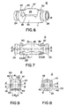
- FIGS. 6, 7, 8 and 9 the sleeve body 12 is depicted in perspective, side, end and end cross-section views, respectively.
- the axis of sleeve body throughbore 15 depicted by axial dashed line A-A (also shown in FIG. 3) extends through the end portions 24 and 25 and across the laterally extending channel 29 therebetween when the locking mechanism is in the locked position.
- axial dashed line A-A also shown in FIG. 3
- a non-circular shape of the throughbore 14 is effected in the end portions 24 and 25 by an upward elongation of the bore by an incremental offset distance OD to form an upper axis A'-A' to accommodate the lead body in both the locked and unlocked positions of the locking member 22 as will become apparent from the following discussion.
- the aligned throughbores 26 and 27 are also elongated top to bottom by the offset distance OD to accommodate the lead body in both positions. Offset distance OD also therefore represents the amount of movement of the locking member 22 between the locked and unlocked positions.
- the top wall 40 of the sleeve body 12 is curved, whereas the side walls 43 and 45 and bottom wall 41 are relatively flat.
- the laterally extending channel 29 is generally rectangular in shape at the channel opening in the top curved top wall 40 and at the channel opening in the bottom wall 41.
- the upper rails 47 and 49 of the side walls 43 and 45 extend above the side wall edges of the top wall channel opening in order to provide a surface against which the jaws of a forceps may be applied in the unlocking operation described below.
- the upper rails 47 and 49 extend above the shallow recess 34 in the locking member curved top wall 36 which itself is flush with the sleeve body 12 curved top wall 40.
- the width Wb of the channel opening in the bottom wall 41 is narrower than the width Wt in the top wall 40 caused by the inwardly projecting lower sections of the side walls 43 and 45.
- the lower sections of the side walls of the push-button locking member 22 are capable of being forced toward one another as they bear against the tapered inner surfaces of the lower sections of the side walls 43 and 45, thereby reducing the inside diameter ID of the locking member throughbore 38.
- the locking member throughbore 38 is centered at the offset A', and the lead body diameter 13 is accommodated loosely within the aligned sections of the sleeve throughbore 15.
- the lead body traversing the aligned sleeve throughbore 15 itself retains the locking mechanism 22 in the unlocked position within the transverse channel 29.
- the locking mechanism 22 is also partially transversely sectioned below its top wall 36 and at the top of throughbore 38 by transverse section 50 shown in FIGS. 3, 10 and 14.
- This transverse section 50 allows the locking member end walls to be compressed toward one another as the locking member 22 is moved downward in the locking direction LD into the locked position and upward in the unlocking direction ULD into the unlocked position past a locking mechanism.
- the locking mechanism includes movable locking detents extending outwardly from the end walls of the locking member 22 and mating fixed locking detents extending inwardly from the end walls of the transverse channel 29 adjacent to the bottom opening thereof.
- the compression is sufficient so that the outwardly extending, movable locking detents in the lower edges of the locking member end walls 62 and 64 can slip over the fixed locking detents 63, 65, 67, 69 formed at the lower edges of each of the inner end walls of the transverse channel 29.
- Two of the fixed locking detents 63 and 65 are shown in FIG. 9, arranged at the depicted angles with respect to the plane of the lower channel opening.
- a like pair of fixed locking detents 67 and 69 is formed in the opposite facing end wall of the transverse channel 29.
- the angular arrangement allows the locking detents 63, 65 and 67, 69 to be aligned at the angles of four movable locking detents formed in four end wall sections of the locking member 22 when the sections are bent inward in the locked position as described below.
- the movable locking detents in the corresponding end wall sections of the locking member 22 are deflected to assume the angles of the fixed detents shown in FIG. 9 as the locking member 22 is depressed downward in the locking direction LD.
- the engagement of the locking detents along one side of the suture body 12 and locking member 22 is depicted in the cross-section view of FIG. 3.
- the locking member 22 is depicted in side, top, bottom, end and end cross-section views.
- the locking member 22 is also preferably formed of a relatively hard, bio-compatible plastic material of the same type as the sleeve body 12.
- the locking member 22 is partially sectioned into four sections 54, 56, 58, 60 each having a free end extending downward from common end walls 62 and 64 by the transverse section 50 through the side walls and a further longitudinal section 52 in the bottom wall extending to the throughbore 38.
- the four sections 54, 56, 58, 60 are bridged together by the top wall 36 extending between end walls 62 and 64 and having the depression 34 formed in its upper surface 36.
- the exterior surfaces of the side walls of the four sections 54, 56, 58, 60 are relatively flat and parallel to one another and dimensioned to slide within the interior channel surfaces of sleeve body side walls 43 and 45.
- Chamfered lower sections of the side walls of each section are angled inward to bear against the inwardly directed lower sections of the sleeve body side walls 43 and 45.
- the longitudinal section 52 is defined by inwardly facing inner surfaces of the four legs or sections 54, 56, 58, 60 that are angled outward to the bottom opening width OW.
- the facing inner surfaces of sections 54 and 56 are forced toward the facing inner surfaces of sections 58 and 60, respectively, reducing the opening width OW of the longitudinal section 52 and also reducing the inner diameter ID of locking member throughbore 38 substantially evenly around its circumference from the depicted unrestrained inner diameter ID.
- the movable locking detents 70, 72, 74, 76 become angularly aligned with the fixed detents 63, 65, 67, 69.
- the end walls 62 and 64 are relatively flat except for spacer bosses 66 and 68, respectively, extending outwardly adjacent to the top wall 36 that center the locking member 22 longitudinally within the channel 29 when it is in the locked position.
- the spacer bosses 66, 68 balance the four outwardly projecting, movable locking detents 70, 72, 74, 76 located adjacent the bottom edges of the end walls 62 and 64, i.e., adjacent the free ends of the four sections 54, 56, 58, 60, respectively, in the end wall surfaces thereof.
- the movable locking detents 70, 72, 74, 76 ride over and engage the fixed locking detents 63, 65, 67, 69 when the sections 54 and 58 are compressed toward the sections 56 and 60, respectively, which is allowed by the transverse section 50.
- the locked engagement of fixed detents 72 and 76 with movable locking detents 65 and 69, respectively, is depicted in FIG. 3. Although only a single movable detent engages a single fixed locking detent in each location of the mating detents, it will be understood that the mating detents may be multiplied in number.
- lower rails 55, 57, 59 and 61 are formed in the bottom edges of the four sections 54, 56, 58, 60, respectively, and are dimensioned by rail depth RD (FIG. 10) to project downward in the locked position depicted in FIG. 3 so that opposed release forces RF and RF' may be applied between them and the upper rails 47 and 49.
- the engagement of the movable and fixed detents is released by release forces RF applied simultaneously in the transverse locking direction LD, against the upper rails 47 and 49 (rather than against the locking member 22) and opposed release forces RF' simultaneously applied and in the transverse unlocking direction ULD against the lower rails 55, 57, 59, 61.
- the jaws of a forceps or a similar, readily available, pliers-like tool may be applied between the lower rails 55, 57, 59 and 61, on the one hand, and the upper rails 47 and 49 on the other hand, and squeezed together.
- the applied compressive release forces RF and RF' push the movable locking detents 70, 72, 74, 76 upward over the fixed locking detents 63, 65, 67, 69, respectively to effect the release and movement in the unlocking direction ULD.
- the locking mechanism of the present invention securely locks the suture sleeve 10 in place with minimal compression of the lead diameter 13 in a band that extends substantially evenly around the circumference of the lead body. It is to be noted from the above description that lead body diameter 13 which is only slightly smaller than the common diameter of the throughbore 15, particularly the inner diameter ID of the movable locking member 22. Since different types of catheters and leads have different diameters, it is contemplated by the inventor that sleeve 10 in accordance with the present invention must be made in different sizes to accommodate differing lead body diameters. It is believed that a person having the benefit of this disclosure would be readily able to practice the present invention with any diameter.
- the locking mechanism comprising the fixed and movable locking detents are depicted as elongated ridges projecting outwardly of the respective end walls of the transverse channel 29 and the end walls 62 and 64, it will be understood that they may take other forms, e.g. hooks or ridges and edges or recesses, and may take other shapes, e.g., square or circular, rather than elongated. Moreover the locking mechanism may alternatively be formed in the opposing side walls of the transverse channel 29.
- Such equivalent structures as will be known to those of skill in the art nevertheless shall allow the substantially even compressive force to be applied substantially all the way around the circumference of the lead body or other elongated structure in the locked position. Such equivalent structures shall additionally allow the locking mechanism to be released by release force applied in the transverse direction against the movable locking member on one side thereof and against the suture body on the other side thereof substantially as illustrated and described above.
- suture sleeve 10 may be unlocked, if necessary, and repositioned along the lead body.
- suture sleeve 10 may be repeatedly locked, unlocked, and repositioned, without difficulty and without risk of damage to the lead.
- push-button locking member 22 might be marked (as with a colored dot or other symbol) in order to assist in differentiating between the top and bottom thereof.
- some portion of suture sleeve 10 may have identifying markings to distinguish, for example, between atrial and ventricular leads, or to identify the size, type or other characteristic of the lead.
Landscapes
- Health & Medical Sciences (AREA)
- Heart & Thoracic Surgery (AREA)
- Life Sciences & Earth Sciences (AREA)
- Veterinary Medicine (AREA)
- Cardiology (AREA)
- Engineering & Computer Science (AREA)
- Biomedical Technology (AREA)
- Public Health (AREA)
- General Health & Medical Sciences (AREA)
- Animal Behavior & Ethology (AREA)
- Hematology (AREA)
- Pulmonology (AREA)
- Biophysics (AREA)
- Anesthesiology (AREA)
- Vascular Medicine (AREA)
- Nuclear Medicine, Radiotherapy & Molecular Imaging (AREA)
- Radiology & Medical Imaging (AREA)
- Surgical Instruments (AREA)
- Materials For Medical Uses (AREA)
Claims (10)
- Manchon de suture (10) conçu pour fixer une structure flexible et allongée (11) de diamètre externe prédéterminé (13) à un tissu de corps de patient, comprenant :un corps de manchon (12) comportant un trou débouchant longitudinal (14), dont les dimensions permettent de recevoir, en l'entourant, ledit diamètre externe de ladite structure allongée, en permettant un mouvement relatif dudit corps de manchon sur ladite structure allongée, ledit corps de manchon comportant un canal transversal (29), coupant ledit trou débouchant longitudinal (15) et comportant une ouverture de canal transversal ;un élément de verrouillage (22), mobile dans ledit canal transversal (29), entre une position déverrouillée et une position verrouillée, et comportant un trou débouchant longitudinal d'élément de verrouillage (38), dont le diamètre de trou débouchant est dimensionné pour recevoir ledit diamètre externe de ladite structure allongée dans lesdites position verrouillée et déverrouillée ; caractérisé en ce queledit élément de verrouillage (22), lorsqu'il est déplacé par une force de verrouillage appliquée dans un sens de verrouillage, se déplace de ladite position déverrouillée, dans laquelle son diamètre de trou débouchant dépasse ledit diamètre externe prédéterminé et permet un mouvement relatif dudit élément de verrouillage (22) et dudit corps de manchon (12) sur ladite structure allongée, vers ladite position verrouillée, dans laquelle ledit diamètre de trou débouchant d'élément de verrouillage est réduit de manière sensiblement uniforme autour de sa circonférence, jusqu'à moins que ledit diamètre prédéterminé, exerçant ainsi une force de manière relativement uniforme autour de la surface externe de ladite structure allongée, dans ledit trou débouchant d'élément de verrouillage, afin d'augmenter sensiblement la résistance frictionnelle s'opposant au mouvement relatif du manchon de suture (10) et de la structure allongée.
- Manchon de suture selon la revendication 1, comprenant de plus :une première et une seconde pièce formant brides (16, 17), chaque pièce formant bride comportant un trou débouchant de pièce formant bride (26, 27), dimensionné pour recevoir ladite structure allongée (11) et placé à une extrémité dudit corps de manchon (12), les trous débouchants de pièces formant brides étant en alignement sensiblement coaxial avec ledit trou débouchant longitudinal du corps de manchon (14), chacune des pièces formant brides étant faite d'un matériau résilient et ayant une longueur suffisante pour réduire le fléchissement important de la structure allongée qui traverse le trou débouchant du corps de manchon.
- Manchon de suture selon la revendication 2, dans lequel lesdites première et seconde pièce formant brides (16, 17) sont placées sur des parties d'extrémité dudit corps de manchon (12) et sont pourvues d'au moins une rainure réceptrice de suture (20, 21), qui y est formée et qui est conçue pour recevoir une suture.
- Manchon de suture selon l'une quelconque des revendications précédentes, dans lequel ledit canal transversal (29) est découpé pour exercer une force de compression sur ledit élément de verrouillage (22) dans ladite position verrouillée, afin de diminuer ledit diamètre de trou débouchant (38) d'élément de verrouillage.
- Manchon de suture selon la revendication 4, dans lequel :ledit élément de verrouillage mobile (22) comporte des parois opposées et une pluralité d'éléments mobiles de verrouillage (70, 72, 74, 76), formés dans ses parois opposées ; etledit canal transversal (29) est formé de parois opposées, dimensionnées de manière analogue, et d'une pluralité d'éléments de verrouillage fixes analogues (63, 65, 67, 69), qui y sont formés, conçus pour que ladite pluralité d'éléments mobiles de verrouillage puisse s'y engager, dans ladite position verrouillée.
- Manchon de suture selon la revendication 4, dans lequel :ledit canal transversal (29) s'étend latéralement à travers le trou débouchant longitudinal (14) dudit corps de manchon (12) et il est bordé par des côtés espacés, qui s'étendent longitudinalement (47, 49), et par des extrémités qui s'étendent latéralement, qui ont au moins une butée fixe (63, 35, 67, 69) qui y est formée ;ledit élément de verrouillage (22) est formé avec des côtés qui s'étendent longitudinalement et par des extrémités qui s'étendent latéralement (62, 64), et ses dimensions lui permettent de rentrer dans ledit canal transversal, lesdites extrémités qui s'étendent latéralement comprenant de plus au moins une butée mobile de verrouillage (70, 72, 74, 76), disposée sur au moins une extrémité dudit élément de verrouillage, pour l'engagement avec ladite au moins une butée fixe de verrouillage dans ledit canal transversal.
- Manchon de suture selon l'une quelconque des revendications 1 à 4, dans lequel :ledit corps de manchon (12) est formé avec ledit canal transversal (29), qui s'étend entre ladite ouverture de canal transversal, formée dans une surface supérieure dudit corps de manchon, et une ouverture de canal située plus bas, dans une surface inférieure dudit corps de manchon, et il est formé avec un premier moyen de libération, situé à proximité de l'ouverture supérieure de canal transversal, contre lequel on peut appliquer une force de libération lorsque ledit élément mobile de verrouillage se trouve dans la position de verrouillage, sans interférence avec lui ; etledit élément mobile de verrouillage (22) est formé avec un second moyen de libération, que l'on peut positionner par rapport à ladite l'ouverture inférieure de canal transversal lorsque ledit élément mobile de verrouillage se trouve dans ladite position de verrouillage, contre lequel on peut appliquer ladite force de libération lorsque ledit élément mobile de verrouillage se trouve dans la position de verrouillage, sans interférence avec ledit corps de manchon.
- Manchon de suture selon l'une quelconque des revendications 1 à 4, dans lequel :ledit corps de manchon (12) est formé avec une surface supérieure et avec une surface inférieure, et avec ledit canal transversal (29), qui s'étend entre ladite ouverture de canal transversal, formée dans ladite surface supérieure, et une ouverture de canal plus basse, située dans ladite surface inférieure, et il est formé avec au moins un rail supérieur (47, 49), adjacent à l'ouverture supérieure de canal transversal, contre lequel on peut appliquer une force de libération quand l'élément mobile de verrouillage (22) se trouve dans la position verrouillée ; etledit élément mobile de verrouillage (22) est formé avec une surface d'élément supérieur, conçue pour être encastrée au-dessous dudit rail supérieur dans ladite position de verrouillage, et avec au moins un rail inférieur, conçu pour traverser ladite ouverture inférieure de canal transversal lorsque ledit élément mobile de verrouillage se trouve dans ladite position verrouillée, de sorte que l'on peut appliquer ladite force de libération entre ledit rail supérieur et ledit rail inférieur, lorsque ledit élément mobile de verrouillage se trouve dans la position verrouillée, en vue d'effectuer le mouvement dudit élément mobile de verrouillage, dans un sens de déverrouillage par rapport au corps de manchon.
- Manchon de suture selon la revendication 4, dans lequel :ledit corps de manchon (12) est formé avec une surface supérieure et avec une surface inférieure opposée, et avec ledit canal transversal (29), qui s'étend entre ladite ouverture de canal transversal, formée dans ladite surface supérieure, et une ouverture de canal plus basse, située dans ladite surface inférieure, et il est formé avec un premier et par un second rail supérieur (47, 49), qui s'étendent le long de ladite ouverture supérieure de canal transversal, contre laquelle on peut appliquer une force de libération quand l'élément mobile de verrouillage (22) se trouve dans la position verrouillée ; etledit élément mobile de verrouillage (22) est formé avec une surface supérieure, découpée pour être encastrée au-dessous desdits rails supérieurs dans ladite position de verrouillage et par le premier et par le second rail inférieur (55, 57, 59, 61), conçus pour traverser ladite ouverture inférieure de canal transversal lorsque ledit élément mobile de verrouillage se trouve dans ladite position verrouillée, de sorte que l'on peut appliquer ladite force de libération (FD) entre lesdits premier et second rail, inférieur et supérieur, lorsque ledit élément mobile de verrouillage se trouve dans la position verrouillée, en vue d'effectuer le mouvement dudit élément mobile de verrouillage, dans un sens de déverrouillage par rapport au corps de manchon.
- Manchon de suture selon l'une quelconque des revendications 1 à 4, dans lequel :ledit corps de manchon (12) est formé avec une surface supérieure (40) et avec une surface inférieure (41), séparées par des parois latérales globalement parallèles (43, 45), et par ledit canal transversal (29), qui s'étend entre ladite ouverture de canal transversal, formée dans ladite surface supérieure dudit corps de manchon, et une ouverture de canal plus basse, située dans ladite surface inférieure dudit corps de manchon, et il est bordé par des parois d'extrémité et par des parois latérales de canal, dans lequel lesdites parois latérales de canal sont formées avec des parties inférieures et allongées, faisant saillie vers l'intérieur, de sorte que ladite ouverture supérieure de canal a une largeur (Wb) plus étroite que celle (Wt) de ladite ouverture supérieure de canal ; etledit élément mobile de verrouillage (22) est formé avec des parois (62, 64) latérales et d'extrémité et par des surfaces supérieures et inférieures, globalement parallèles, dimensionnées pour rentrer dans ladite ouverture supérieure de canal transversal et pour venir en force vers ladite ouverture supérieure de canal quand on lui applique une force de verrouillage, et avec une partie qui s'y étend longitudinalement, qui traverse ladite surface inférieure vers ledit trou débouchant d'élément de verrouillage (38), divisant ainsi ledit élément de verrouillage en au moins deux parties (54, 56, 58, 60), qui s'étendent en partant de ladite surface supérieure de celui-ci, de sorte que lors d'un mouvement dudit élément de verrouillage vers ladite position de verrouillage, lesdites parties allongées exercent une force de compression contre lesdites deux parties dudit élément de verrouillage, afin de les tirer ensemble et de diminuer ledit diamètre de trou débouchant d'élément de verrouillage.
Applications Claiming Priority (3)
| Application Number | Priority Date | Filing Date | Title |
|---|---|---|---|
| US08/795,425 US5746722A (en) | 1997-02-05 | 1997-02-05 | Suture sleeve with circumferential lead locking device |
| US795425 | 1997-02-05 | ||
| PCT/US1998/000295 WO1998033551A1 (fr) | 1997-02-05 | 1998-01-09 | Manchon de suture a dispositif de blocage de fil circonferentiel |
Publications (2)
| Publication Number | Publication Date |
|---|---|
| EP1011788A1 EP1011788A1 (fr) | 2000-06-28 |
| EP1011788B1 true EP1011788B1 (fr) | 2003-11-19 |
Family
ID=25165481
Family Applications (1)
| Application Number | Title | Priority Date | Filing Date |
|---|---|---|---|
| EP98901727A Expired - Lifetime EP1011788B1 (fr) | 1997-02-05 | 1998-01-09 | Manchon de suture avec un dispositif de blocage de tube circonferentiel |
Country Status (7)
| Country | Link |
|---|---|
| US (1) | US5746722A (fr) |
| EP (1) | EP1011788B1 (fr) |
| JP (1) | JP2001510362A (fr) |
| AU (1) | AU5818098A (fr) |
| CA (1) | CA2279984C (fr) |
| DE (1) | DE69819913T2 (fr) |
| WO (1) | WO1998033551A1 (fr) |
Cited By (1)
| Publication number | Priority date | Publication date | Assignee | Title |
|---|---|---|---|---|
| US9585654B2 (en) | 2012-05-01 | 2017-03-07 | Dean & Webb, LLC | Segmentally rigid suture and suturing technique |
Families Citing this family (59)
| Publication number | Priority date | Publication date | Assignee | Title |
|---|---|---|---|---|
| US6473654B1 (en) * | 2000-03-08 | 2002-10-29 | Advanced Bionics Corporation | Lead anchor |
| AU2001257005B2 (en) | 2000-04-10 | 2006-03-02 | Boston Scientific Limited | Locking catheter |
| US6901287B2 (en) | 2001-02-09 | 2005-05-31 | Medtronic, Inc. | Implantable therapy delivery element adjustable anchor |
| US6782290B2 (en) * | 2001-04-27 | 2004-08-24 | Medtronic, Inc. | Implantable medical device with rechargeable thin-film microbattery power source |
| US6997919B2 (en) * | 2002-04-23 | 2006-02-14 | Medtronic, Inc. | Implantable medical connector for medical tubing with anchoring features |
| US7499755B2 (en) * | 2002-10-23 | 2009-03-03 | Medtronic, Inc. | Paddle-style medical lead and method |
| WO2004064936A2 (fr) * | 2003-01-23 | 2004-08-05 | Daley Richard A | Dispositif de rouler pour le golf |
| US7217251B2 (en) * | 2004-04-22 | 2007-05-15 | Medtronic, Inc. | Pressure relief methods in a medical catheter system |
| EP1747390B1 (fr) * | 2004-04-22 | 2008-03-12 | Medtronic, Inc. | Procedes de decompression dans un systeme de catheter medical |
| US7184841B1 (en) * | 2004-08-19 | 2007-02-27 | Cardiac Pacemakers, Inc. | Pacing lead stabilizer |
| US20060127158A1 (en) * | 2004-10-21 | 2006-06-15 | Medtronic, Inc. | Implantable electrical lead retention system and method |
| US7930039B2 (en) * | 2005-01-07 | 2011-04-19 | Medtronic, Inc. | Implantable retention system and method |
| US20060264803A1 (en) * | 2005-04-26 | 2006-11-23 | Cook Vascular Incorporated | Suture collar |
| EP1933934B1 (fr) * | 2005-08-24 | 2011-10-12 | St. Jude Medical AB | Douille de suture dotee d'un mecanisme de verrouillage de fil |
| US7831313B2 (en) * | 2005-08-26 | 2010-11-09 | Boston Scientific Neuromodulation Corporation | Lead anchor for implantable stimulation devices and methods of manufacture and use |
| US7787960B2 (en) * | 2007-02-15 | 2010-08-31 | Boston Scientific Neuromodulation Corporation | Lead anchoring assembly |
| US7899553B2 (en) * | 2007-03-28 | 2011-03-01 | Boston Scientific Neuromodulation Corporation | Lead anchor for implantable stimulation devices |
| US8430852B2 (en) * | 2007-04-17 | 2013-04-30 | Medtronic, Inc. | Therapeutic sleeve for implantable medical device |
| US20080275401A1 (en) * | 2007-05-01 | 2008-11-06 | Sage Shahn S | Catheter anchor and system/method regarding same |
| US20090112301A1 (en) * | 2007-10-25 | 2009-04-30 | Kowalczyk James M | Strain Relief System For Spinal Cord Stimulation Lead |
| US8249719B2 (en) * | 2007-11-09 | 2012-08-21 | Cardiac Pacemakers, Inc. | Lead stabilizer with retention features |
| US8126569B2 (en) * | 2007-11-09 | 2012-02-28 | Cardiac Pacemakers, Inc. | Compression control lead anchoring device |
| US8632502B2 (en) | 2008-03-27 | 2014-01-21 | Medtronic, Inc. | Anchor deployment apparatus |
| US8262624B2 (en) * | 2008-03-27 | 2012-09-11 | Medtronic, Inc. | Anchor and anchor deployment apparatus |
| EP2271393B1 (fr) * | 2008-03-28 | 2015-06-17 | St. Jude Medical AB | Manchon de suture |
| US8140172B1 (en) * | 2008-07-11 | 2012-03-20 | Advanced Neuromodulation Systems, Inc. | Implantable anchor with locking arm |
| EP2349080B1 (fr) * | 2008-10-22 | 2016-04-13 | Boston Scientific Scimed, Inc. | Endoprothèse vasculaire tubulaire à mémoire de forme comportant des rainures |
| WO2010090858A2 (fr) * | 2009-01-21 | 2010-08-12 | Medtronic, Inc. | Systèmes cathéters comportant des réducteurs de débit |
| US9887470B2 (en) * | 2009-04-27 | 2018-02-06 | Boston Scienific Neuromodulation Corporation | Torque lock anchor and methods and devices using the anchor |
| US9352147B2 (en) * | 2009-04-27 | 2016-05-31 | Boston Scientific Neuromodulation Corporation | Torque lock anchor and methods and devices using the anchor |
| US8295948B2 (en) * | 2009-07-21 | 2012-10-23 | Boston Scientific Neuromodulation Corporation | Tubular lead anchor and methods and devices using the anchor |
| US9974944B2 (en) | 2010-07-29 | 2018-05-22 | Cameron Health, Inc. | Subcutaneous leads and methods of implant and explant |
| US9517332B2 (en) * | 2011-01-27 | 2016-12-13 | Medtronic, Inc. | Anchors including rigid bodies defining full length slots for use with implantable medical leads |
| WO2012103123A2 (fr) | 2011-01-28 | 2012-08-02 | Medtronic, Inc. | Système d'ancrage repositionnable pour élément d'administration thérapeutique |
| US9402993B2 (en) | 2011-04-11 | 2016-08-02 | Boston Scientific Neuromodulation Corporation | Systems and methods for enhancing paddle lead placement |
| EP2788073B1 (fr) | 2011-11-10 | 2018-03-21 | Medtronic Inc. | Outil d'introduction et d'ancrage pour un élément de dispositif médical implantable |
| ES2829585T3 (es) * | 2012-01-25 | 2021-06-01 | Nevro Corp | Anclajes de cables y sistemas y métodos asociados |
| ES2589879T3 (es) * | 2012-03-22 | 2016-11-16 | Boston Scientific Neuromodulation Corporation | Anclaje de bloqueo de par y procedimientos y dispositivos que utilizan el anclaje |
| WO2014070680A1 (fr) | 2012-10-29 | 2014-05-08 | Cardiac Pacemakers, Inc. | Manchons de suture ayant une résistance à la déchirure de surface extérieure |
| US9486622B2 (en) | 2012-11-08 | 2016-11-08 | Cardiac Pacemakers, Inc. | Fixation and strain relief element for temporary therapy delivery device |
| US9539382B2 (en) | 2013-03-12 | 2017-01-10 | Medtronic, Inc. | Stepped catheters with flow restrictors and infusion systems using the same |
| US20150005856A1 (en) * | 2013-06-27 | 2015-01-01 | Boston Scientific Neuromodulation Corporation | Lead anchors and systems and methods using the lead anchors |
| US9216563B2 (en) | 2013-08-19 | 2015-12-22 | Boston Scientific Neuromodulation Corporation | Lead anchor with adhesive and systems and methods using the lead anchor |
| US9517334B2 (en) | 2013-08-19 | 2016-12-13 | Boston Scientific Neuromodulation Corporation | Lead anchors and systems and methods employing the lead anchors |
| US9095701B2 (en) * | 2013-08-30 | 2015-08-04 | Boston Scientific Neuromodulation Corporation | Systems and methods for making and using lead anchors for leads of electrical stimulation systems |
| US9480822B2 (en) | 2013-12-23 | 2016-11-01 | Hologic, Inc. | Locking device |
| US9415212B2 (en) | 2014-02-28 | 2016-08-16 | Boston Scientific Neuromodulation Corporation | Side loading lead anchor and methods of making and using thereof |
| US9987482B2 (en) | 2014-05-27 | 2018-06-05 | Boston Scientific Neuromodulation Corporation | Systems and methods for making and using reversible mechanical lead anchors for electrical stimulation systems |
| US11135350B2 (en) * | 2015-01-27 | 2021-10-05 | Stacey JACOVINI | Catheter anchor drain |
| WO2016187473A1 (fr) | 2015-05-20 | 2016-11-24 | Cardiac Pacemakers, Inc. | Stabilisateur de sonde entièrement intégré pour sondes électriques médicales et procédés de fixation associés |
| US10617402B2 (en) | 2015-07-22 | 2020-04-14 | Cameron Health, Inc. | Minimally invasive method to implant a subcutaneous electrode |
| US9636498B2 (en) | 2015-08-03 | 2017-05-02 | Boston Scientific Neuromodulation Corporation | Lead anchor with a wedge and systems using the lead anchor |
| WO2017151438A1 (fr) | 2016-02-29 | 2017-09-08 | Boston Scientific Neuromodulation Corporation | Point d'ancrage de conducteur électrique pour système de stimulation électrique |
| US10603483B2 (en) | 2016-04-28 | 2020-03-31 | Medtronic, Inc. | Lead implant fixation mechanism |
| US10369354B2 (en) | 2016-05-17 | 2019-08-06 | Boston Scientific Neuromodulation Corporation | Systems and method for anchoring a lead for neurostimulation of a target anatomy |
| US10709886B2 (en) | 2017-02-28 | 2020-07-14 | Boston Scientific Neuromodulation Corporation | Electrical stimulation leads and systems with elongate anchoring elements and methods of making and using |
| US10835739B2 (en) | 2017-03-24 | 2020-11-17 | Boston Scientific Neuromodulation Corporation | Electrical stimulation leads and systems with elongate anchoring elements and methods of making and using |
| US10857351B2 (en) | 2017-04-28 | 2020-12-08 | Boston Scientific Neuromodulation Corporation | Lead anchors for electrical stimulation leads and systems and methods of making and using |
| DE102018112560A1 (de) | 2018-05-25 | 2019-11-28 | Biotronik Se & Co. Kg | Elektrodenfixierhülse mit optischem Kraftindikator |
Family Cites Families (27)
| Publication number | Priority date | Publication date | Assignee | Title |
|---|---|---|---|---|
| US3176690A (en) * | 1961-05-26 | 1965-04-06 | Doubler Peter B H | Catheter having integral, polymeric flanges |
| US3176600A (en) | 1962-06-06 | 1965-04-06 | Tokar George | Cam controlled diaphragm and focus coaction |
| US3730187A (en) * | 1971-01-22 | 1973-05-01 | V Reynolds | Sew-in urethral catheter |
| US3724467A (en) * | 1971-04-23 | 1973-04-03 | Avery Labor Inc | Electrode implant for the neuro-stimulation of the spinal cord |
| US3821957A (en) * | 1973-05-02 | 1974-07-02 | East West Med Prod | Retention slide for catheters and other tubular materials |
| US3880169A (en) * | 1974-01-02 | 1975-04-29 | American Hospital Supply Corp | Controlled entry pacemaker electrode for myocardial implantation |
| US4276882A (en) * | 1979-05-18 | 1981-07-07 | Medtronic, Inc. | Lead anchoring device |
| US4287891A (en) * | 1979-08-31 | 1981-09-08 | Peters Joseph L | Securing device for surgical tubes |
| US4266552A (en) * | 1979-11-13 | 1981-05-12 | Medtronic, Inc. | Lead anchoring bobbin |
| US4516584A (en) * | 1983-01-07 | 1985-05-14 | Cordis Corporation | Suture collar |
| US4553961A (en) * | 1984-04-18 | 1985-11-19 | Cordis Corporation | Suture sleeve with structure for enhancing pacing lead gripping |
| US4683895A (en) * | 1985-07-25 | 1987-08-04 | Cordis Corporation | Suture sleeve anchoring device |
| US5129405A (en) * | 1985-09-18 | 1992-07-14 | Telectronics N.V. | Vein suture collar |
| US4672979A (en) * | 1986-01-30 | 1987-06-16 | Cordis Corporation | Suture sleeve assembly |
| US4764132A (en) * | 1986-03-28 | 1988-08-16 | Siemens-Pacesetter, Inc. | Pacemaker connector block for proximal ring electrode |
| US4860750A (en) * | 1986-04-17 | 1989-08-29 | Intermedics Inc. | Sidelock pacer lead connector |
| US4848346A (en) * | 1987-12-02 | 1989-07-18 | Siemens-Pacesetter, Inc. | Pacemaker connector system |
| US4934366A (en) * | 1988-09-01 | 1990-06-19 | Siemens-Pacesetter, Inc. | Feedthrough connector for implantable medical device |
| US5275620A (en) * | 1990-05-21 | 1994-01-04 | Telectronics, N.V. | Implantable lead connectors and remote lead assembly |
| US5107856A (en) * | 1991-01-10 | 1992-04-28 | Siemens-Pacesetter, Inc. | Multiple lead suture sleeve |
| US5152298A (en) * | 1991-04-16 | 1992-10-06 | Siemens Pacesetter, Inc. | Threaded suture sleeve |
| US5242431A (en) * | 1992-06-11 | 1993-09-07 | Siemens Pacesetter, Inc. | Suture sleeve assembly with slidable compression collar |
| US5273053A (en) * | 1992-11-02 | 1993-12-28 | Medtronic, Inc. | Suture sleeve with lead locking device |
| US5338313A (en) * | 1992-12-17 | 1994-08-16 | Thomas J. Fogarty, M.D. | Adjustable valve having a radially compressible sealing body |
| US5476493A (en) * | 1993-05-19 | 1995-12-19 | Pacesetter, Inc. | Implantable lead having self-locking suture sleeve |
| US5413595A (en) * | 1993-10-15 | 1995-05-09 | Pacesetter, Inc. | Lead retention and seal for implantable medical device |
| US5584874A (en) * | 1995-04-28 | 1996-12-17 | Medtronic, Inc. | Medical electrical lead having improved anchoring sleeve |
-
1997
- 1997-02-05 US US08/795,425 patent/US5746722A/en not_active Expired - Lifetime
-
1998
- 1998-01-09 WO PCT/US1998/000295 patent/WO1998033551A1/fr active IP Right Grant
- 1998-01-09 EP EP98901727A patent/EP1011788B1/fr not_active Expired - Lifetime
- 1998-01-09 DE DE69819913T patent/DE69819913T2/de not_active Expired - Lifetime
- 1998-01-09 AU AU58180/98A patent/AU5818098A/en not_active Abandoned
- 1998-01-09 CA CA002279984A patent/CA2279984C/fr not_active Expired - Fee Related
- 1998-01-09 JP JP53289698A patent/JP2001510362A/ja active Pending
Cited By (1)
| Publication number | Priority date | Publication date | Assignee | Title |
|---|---|---|---|---|
| US9585654B2 (en) | 2012-05-01 | 2017-03-07 | Dean & Webb, LLC | Segmentally rigid suture and suturing technique |
Also Published As
| Publication number | Publication date |
|---|---|
| CA2279984A1 (fr) | 1998-08-06 |
| AU5818098A (en) | 1998-08-25 |
| EP1011788A1 (fr) | 2000-06-28 |
| JP2001510362A (ja) | 2001-07-31 |
| WO1998033551A1 (fr) | 1998-08-06 |
| DE69819913T2 (de) | 2004-07-29 |
| DE69819913D1 (de) | 2003-12-24 |
| CA2279984C (fr) | 2002-12-10 |
| US5746722A (en) | 1998-05-05 |
Similar Documents
| Publication | Publication Date | Title |
|---|---|---|
| EP1011788B1 (fr) | Manchon de suture avec un dispositif de blocage de tube circonferentiel | |
| AU655373B2 (en) | Suture sleeve with lead locking device | |
| US5957968A (en) | Suture sleeve with lead locking device | |
| US7787960B2 (en) | Lead anchoring assembly | |
| US4683895A (en) | Suture sleeve anchoring device | |
| US11832807B2 (en) | System and method for securing an implant to tissue | |
| US4672979A (en) | Suture sleeve assembly | |
| US7359756B2 (en) | Method of removing an elongated structure implanted in biological tissue | |
| US6554802B1 (en) | Medical catheter anchor | |
| US5584874A (en) | Medical electrical lead having improved anchoring sleeve | |
| US5603730A (en) | Suture sleeve for implantable lead | |
| US5824032A (en) | Medical electrical lead featuring a one piece lead anchoring sleeve with wrap-around locking arms | |
| CA1161122A (fr) | Bobine de calage pour tube | |
| US20060127158A1 (en) | Implantable electrical lead retention system and method | |
| WO2006036058A2 (fr) | Element de fixation implantable | |
| US20100324569A1 (en) | Suture sleeve and a method for positioning a suture sleeve and a lead in relation to each other |
Legal Events
| Date | Code | Title | Description |
|---|---|---|---|
| PUAI | Public reference made under article 153(3) epc to a published international application that has entered the european phase |
Free format text: ORIGINAL CODE: 0009012 |
|
| 17P | Request for examination filed |
Effective date: 19990730 |
|
| AK | Designated contracting states |
Kind code of ref document: A1 Designated state(s): CH DE FR LI NL SE |
|
| GRAH | Despatch of communication of intention to grant a patent |
Free format text: ORIGINAL CODE: EPIDOS IGRA |
|
| GRAS | Grant fee paid |
Free format text: ORIGINAL CODE: EPIDOSNIGR3 |
|
| GRAA | (expected) grant |
Free format text: ORIGINAL CODE: 0009210 |
|
| PGFP | Annual fee paid to national office [announced via postgrant information from national office to epo] |
Ref country code: NL Payment date: 20031112 Year of fee payment: 7 |
|
| AK | Designated contracting states |
Kind code of ref document: B1 Designated state(s): CH DE FR LI NL SE |
|
| REG | Reference to a national code |
Ref country code: CH Ref legal event code: EP |
|
| REF | Corresponds to: |
Ref document number: 69819913 Country of ref document: DE Date of ref document: 20031224 Kind code of ref document: P |
|
| REG | Reference to a national code |
Ref country code: SE Ref legal event code: TRGR |
|
| REG | Reference to a national code |
Ref country code: CH Ref legal event code: NV Representative=s name: A. BRAUN, BRAUN, HERITIER, ESCHMANN AG PATENTANWAE |
|
| ET | Fr: translation filed | ||
| RAP2 | Party data changed (patent owner data changed or rights of a patent transferred) |
Owner name: MEDTRONIC, INC. |
|
| PLBE | No opposition filed within time limit |
Free format text: ORIGINAL CODE: 0009261 |
|
| STAA | Information on the status of an ep patent application or granted ep patent |
Free format text: STATUS: NO OPPOSITION FILED WITHIN TIME LIMIT |
|
| NLT2 | Nl: modifications (of names), taken from the european patent patent bulletin |
Owner name: MEDTRONIC, INC. |
|
| 26N | No opposition filed |
Effective date: 20040820 |
|
| PG25 | Lapsed in a contracting state [announced via postgrant information from national office to epo] |
Ref country code: NL Free format text: LAPSE BECAUSE OF NON-PAYMENT OF DUE FEES Effective date: 20050801 |
|
| NLV4 | Nl: lapsed or anulled due to non-payment of the annual fee |
Effective date: 20050801 |
|
| PGFP | Annual fee paid to national office [announced via postgrant information from national office to epo] |
Ref country code: CH Payment date: 20070110 Year of fee payment: 10 |
|
| PGFP | Annual fee paid to national office [announced via postgrant information from national office to epo] |
Ref country code: SE Payment date: 20080107 Year of fee payment: 11 |
|
| REG | Reference to a national code |
Ref country code: CH Ref legal event code: PFA Owner name: MEDTRONIC, INC. Free format text: MEDTRONIC, INC.#7000 CENTRAL AVENUE N.E.#MINNEAPOLIS, MINNESOTA 55432 (US) -TRANSFER TO- MEDTRONIC, INC.#7000 CENTRAL AVENUE N.E.#MINNEAPOLIS, MINNESOTA 55432 (US) |
|
| REG | Reference to a national code |
Ref country code: CH Ref legal event code: PL |
|
| PG25 | Lapsed in a contracting state [announced via postgrant information from national office to epo] |
Ref country code: LI Free format text: LAPSE BECAUSE OF NON-PAYMENT OF DUE FEES Effective date: 20080131 Ref country code: CH Free format text: LAPSE BECAUSE OF NON-PAYMENT OF DUE FEES Effective date: 20080131 |
|
| EUG | Se: european patent has lapsed | ||
| PG25 | Lapsed in a contracting state [announced via postgrant information from national office to epo] |
Ref country code: SE Free format text: LAPSE BECAUSE OF NON-PAYMENT OF DUE FEES Effective date: 20090110 |
|
| PGFP | Annual fee paid to national office [announced via postgrant information from national office to epo] |
Ref country code: FR Payment date: 20120130 Year of fee payment: 15 |
|
| PGFP | Annual fee paid to national office [announced via postgrant information from national office to epo] |
Ref country code: DE Payment date: 20120127 Year of fee payment: 15 |
|
| REG | Reference to a national code |
Ref country code: FR Ref legal event code: ST Effective date: 20130930 |
|
| PG25 | Lapsed in a contracting state [announced via postgrant information from national office to epo] |
Ref country code: DE Free format text: LAPSE BECAUSE OF NON-PAYMENT OF DUE FEES Effective date: 20130801 |
|
| REG | Reference to a national code |
Ref country code: DE Ref legal event code: R119 Ref document number: 69819913 Country of ref document: DE Effective date: 20130801 |
|
| PG25 | Lapsed in a contracting state [announced via postgrant information from national office to epo] |
Ref country code: FR Free format text: LAPSE BECAUSE OF NON-PAYMENT OF DUE FEES Effective date: 20130131 |