EP1010863B1 - Assembly method for variable vanes - Google Patents
Assembly method for variable vanes Download PDFInfo
- Publication number
- EP1010863B1 EP1010863B1 EP99310158A EP99310158A EP1010863B1 EP 1010863 B1 EP1010863 B1 EP 1010863B1 EP 99310158 A EP99310158 A EP 99310158A EP 99310158 A EP99310158 A EP 99310158A EP 1010863 B1 EP1010863 B1 EP 1010863B1
- Authority
- EP
- European Patent Office
- Prior art keywords
- vane
- spacer
- assembly
- casing
- seats
- Prior art date
- Legal status (The legal status is an assumption and is not a legal conclusion. Google has not performed a legal analysis and makes no representation as to the accuracy of the status listed.)
- Expired - Lifetime
Links
- 238000000034 method Methods 0.000 title claims description 10
- 125000006850 spacer group Chemical group 0.000 claims description 36
- 238000007789 sealing Methods 0.000 claims description 9
- 238000006243 chemical reaction Methods 0.000 description 4
- 239000000523 sample Substances 0.000 description 4
- 230000000712 assembly Effects 0.000 description 3
- 238000000429 assembly Methods 0.000 description 3
- 238000002485 combustion reaction Methods 0.000 description 3
- 239000002131 composite material Substances 0.000 description 3
- 229920006362 Teflon® Polymers 0.000 description 2
- 239000000835 fiber Substances 0.000 description 2
- 239000011521 glass Substances 0.000 description 2
- 229920001721 polyimide Polymers 0.000 description 2
- 239000009719 polyimide resin Substances 0.000 description 2
- 230000007423 decrease Effects 0.000 description 1
- 230000003247 decreasing effect Effects 0.000 description 1
- 230000006866 deterioration Effects 0.000 description 1
- 238000006073 displacement reaction Methods 0.000 description 1
- 230000009977 dual effect Effects 0.000 description 1
- 239000000446 fuel Substances 0.000 description 1
- 238000011835 investigation Methods 0.000 description 1
- 239000000463 material Substances 0.000 description 1
- 238000005259 measurement Methods 0.000 description 1
- 239000000203 mixture Substances 0.000 description 1
- 239000000126 substance Substances 0.000 description 1
Images
Classifications
-
- F—MECHANICAL ENGINEERING; LIGHTING; HEATING; WEAPONS; BLASTING
- F01—MACHINES OR ENGINES IN GENERAL; ENGINE PLANTS IN GENERAL; STEAM ENGINES
- F01D—NON-POSITIVE DISPLACEMENT MACHINES OR ENGINES, e.g. STEAM TURBINES
- F01D17/00—Regulating or controlling by varying flow
- F01D17/10—Final actuators
- F01D17/12—Final actuators arranged in stator parts
- F01D17/14—Final actuators arranged in stator parts varying effective cross-sectional area of nozzles or guide conduits
- F01D17/16—Final actuators arranged in stator parts varying effective cross-sectional area of nozzles or guide conduits by means of nozzle vanes
- F01D17/162—Final actuators arranged in stator parts varying effective cross-sectional area of nozzles or guide conduits by means of nozzle vanes for axial flow, i.e. the vanes turning around axes which are essentially perpendicular to the rotor centre line
-
- F—MECHANICAL ENGINEERING; LIGHTING; HEATING; WEAPONS; BLASTING
- F01—MACHINES OR ENGINES IN GENERAL; ENGINE PLANTS IN GENERAL; STEAM ENGINES
- F01D—NON-POSITIVE DISPLACEMENT MACHINES OR ENGINES, e.g. STEAM TURBINES
- F01D25/00—Component parts, details, or accessories, not provided for in, or of interest apart from, other groups
- F01D25/28—Supporting or mounting arrangements, e.g. for turbine casing
-
- F—MECHANICAL ENGINEERING; LIGHTING; HEATING; WEAPONS; BLASTING
- F05—INDEXING SCHEMES RELATING TO ENGINES OR PUMPS IN VARIOUS SUBCLASSES OF CLASSES F01-F04
- F05D—INDEXING SCHEME FOR ASPECTS RELATING TO NON-POSITIVE-DISPLACEMENT MACHINES OR ENGINES, GAS-TURBINES OR JET-PROPULSION PLANTS
- F05D2230/00—Manufacture
- F05D2230/60—Assembly methods
- F05D2230/64—Assembly methods using positioning or alignment devices for aligning or centring, e.g. pins
-
- Y—GENERAL TAGGING OF NEW TECHNOLOGICAL DEVELOPMENTS; GENERAL TAGGING OF CROSS-SECTIONAL TECHNOLOGIES SPANNING OVER SEVERAL SECTIONS OF THE IPC; TECHNICAL SUBJECTS COVERED BY FORMER USPC CROSS-REFERENCE ART COLLECTIONS [XRACs] AND DIGESTS
- Y10—TECHNICAL SUBJECTS COVERED BY FORMER USPC
- Y10T—TECHNICAL SUBJECTS COVERED BY FORMER US CLASSIFICATION
- Y10T29/00—Metal working
- Y10T29/49—Method of mechanical manufacture
- Y10T29/49316—Impeller making
- Y10T29/4932—Turbomachine making
- Y10T29/49323—Assembling fluid flow directing devices, e.g., stators, diaphragms, nozzles
-
- Y—GENERAL TAGGING OF NEW TECHNOLOGICAL DEVELOPMENTS; GENERAL TAGGING OF CROSS-SECTIONAL TECHNOLOGIES SPANNING OVER SEVERAL SECTIONS OF THE IPC; TECHNICAL SUBJECTS COVERED BY FORMER USPC CROSS-REFERENCE ART COLLECTIONS [XRACs] AND DIGESTS
- Y10—TECHNICAL SUBJECTS COVERED BY FORMER USPC
- Y10T—TECHNICAL SUBJECTS COVERED BY FORMER US CLASSIFICATION
- Y10T29/00—Metal working
- Y10T29/49—Method of mechanical manufacture
- Y10T29/49316—Impeller making
- Y10T29/4932—Turbomachine making
- Y10T29/49325—Shaping integrally bladed rotor
Definitions
- the present invention relates to assembly methods and fixtures therefor. More particularly, this invention relates to a fixture and method for assembling a variable stator vane assembly of a gas turbine engine, by which components of the vane assembly can be selected to compensate for part variances and thereby optimize the operation and service life of the assembly.
- Conventional gas turbine engines generally operate on the principle of compressing air within a compressor section of the engine, and then delivering the compressed air to the combustion section of the engine where fuel is added to the air and ignited. Afterwards, the resulting combustion mixture is delivered to the turbine section of the engine, where a portion of the energy generated by the combustion process is extracted by a turbine to drive the engine compressor.
- stator vanes are placed at the entrance and exit of the compressor section and between adjacent compressor stages in order to direct the air flow to each successive compressor stage.
- Variable stator vanes whose pitch can be adjusted relative to the axis of the compressor, are able to enhance engine performance by altering the air flow through the compressor section in response to the changing requirements of the gas turbine engine.
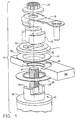
- a high pressure compressor variable stator vane assembly 10 is shown in Figures 1 and 2.
- the assembly 10 includes a stator vane 12 mounted within an opening 38 in a casing 22 of a gas turbine engine.
- the stator vane 12 is designed to rotate within the opening 38 of the casing 22.
- the vane 12 shown in Figures 1 and 2 has a radially extending flange 30 from which an annular-shaped portion extends axially to define a pair of seats 28 (unless otherwise noted, radial and axial directions referred to are with reference to the centerline of the vane assembly 10, and not the radial and axial directions of the engine in which the assembly 10 will be installed).
- a trunnion 34 also extends axially relative to the flange 30, and with the seats 28 projects through the opening 38 as seen in Figure 2.
- the vane 12 is secured to the casing 22 with a nut 20 that also secures a spacer 14, sleeve 16 and lever arm 18 to the trunnion 34. Rotation of the vane 12 within the opening 38 is caused by actuation hardware (not shown) attached to the lever arm 18.
- a seal assembly is shown as consisting of a bushing 24 and washer 26 between the spacer 14 and flange 30 on opposite sides of the casing 22.
- the bushing 24 and washer 26 are preferably molded from composite materials, such as polyimide resin with glass and TEFLON® fibers, in order to be environmentally compatible with the engine environment, as well as provide suitable low-friction bearing surfaces that enable the vane 12 to rotate at acceptable torque levels.
- the ability to minimize radial air leakage from the compressor through the opening 38 of the casing 22 is an important function of the bushing 24 and washer 26.
- the dual functions of the bushing 24 and washer 26 to form an air seal yet enable rotation of the vane 12 are determined by the clearance (radial relative to the axis of the compressor) through the bushing 24 and washer 26 between the flange 30 of the vane 12 and an outer annular surface 36 of the spacer 14.
- the vane 12 and spacer 14 must be assembled to the casing 22 so that the minimum possible clearance is achieved.
- the clearance through the bushing 24 and washer 26 is determined by the axial offset dimension "D" between the annular surface 36 and a pair of shoulder 32 of the spacer 14.
- D the axial offset dimension
- each of the shoulders 32 abuts one of the seats 28 of the vane 12 as shown in Figure 2.
- Increasing the offset dimension D reduces the clearance through the vane 12 and spacer 14 but increases the actuation torque required to rotate the vane 12, while decreasing the offset dimensions D increases the clearance but decreases the actuation torque.
- variable stator vane assemblies of the type shown in Figures 1 and 2 have been assembled to attain a torque level within an acceptable range for the actuation hardware. Because it has been assumed that a close relationship exists between the offset dimension D and the torque required to rotate the vane 12, spacers 14 with incrementally different offset dimensions D have been purposely manufactured to allow adjustment of both the actuation torque and radial clearance by substituting spacers 14. After assembly, if the torque required to rotate a vane is outside preestablished torque limits, the nut 20, lever arm 18, sleeve 16 and spacer 14 are removed and the spacer 14 replaced with another having a different offset dimension D.
- US 5,509,780 discloses arcuate seal segments having radially directed seal faces forming part of a labyrinth seal in a turbine.
- US 5,308,226 discloses a variable angle stator vane assembly for an axial flow gas turbine engine compressor.
- an assembly method for assisting in the matching of components of a variable stator vane assembly of a gas turbine engine.
- components of the vane assembly are matched so that part variances are compensated for to minimize radial clearance while also achieving acceptable actuation torque levels, with the result that the operation and service life of the assembly are optimized.
- an appropriate spacer is selected for the vane based on conditions corresponding to what will exist in the final assembly when properly installed. More particularly, the seal assembly composed of the sealing members is compressed under a load that flattens the sealing members and minor surface irregularities that would otherwise create drag torque when the spacer is mounted to the vane. In this condition, the offset dimension required for the spacer to provide the desired radial clearance through the seal assembly can be more accurately determined, with the result that repeated assembly and disassembly of the vane assembly is unnecessary.
- a significant advantage of this invention is that an improved assembly method is provided that significantly reduces the time to assemble a variable stator vane assembly, and simultaneously more accurately and consistently achieves a vane assembly whose radial clearance is minimized for an acceptable actuation torque level.
- the present invention provides a method for assembling a variable stator vane assembly for use in a gas turbine engine.
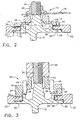
- the method entails preassembling a vane assembly of the general type shown in Figures 1 and 2 with a fixture 40, which enables the vane assembly to be more accurately, quickly and repeatably assembled while achieving minimal air leakage and acceptable actuation torque levels. While the invention will be described with reference to the vane assembly 10 of Figures 1 and 2, those skilled in the art will appreciate that the invention is applicable to vane assemblies that differ from that shown.
- variable stator vane assembly 10 includes the stator vane 12 rotatably mounted within the opening 38 in the casing 22 of a gas turbine engine, with the seats 28 and trunnion 34 extending axially relative to the flange 30 and through the opening 38.
- the vane 12, spacer 14, sleeve 16 and lever arm 18 are all secured to the trunnion 34 with the nut 20.
- the seal assembly that reduces leakage through the vane/spacer interface includes the bushing 24 and washer 26, which may be formed of a variety of materials, preferably composites such as polyimide resin with glass and TEFLON® fibers. While a two-piece seal assembly is shown, different seal assembly configurations and designs can be used with this invention.
- the radial clearance between the casing 22, the flange 30 of the vane 12, and the annular surface 36 of the spacer 14 is determined by the axial offset dimension "D" between the annular surface 36 and the shoulders 32 on the spacer 14. Therefore, the determination of an optimal offset dimension D is critical to minimizing air leakage through the assembly 10 while maintaining an acceptable torque level required to rotate the vane 12.
- the bushing 24 and washer 26 can have interferences with the vane 12, spacer 14 and casing 22, making a prediction of the radial clearance through the assembly 10 impossible.
- the fixture 40 serves to determine the optimal offset dimension D under a specified clamping load for the spacer 14 based on the actual dimensions of the vane 12, casing 22, bushing 24 and washer 26, as well as the unpredictable irregularities and interferences between these components that determine the interrelationship between the radial clearance and actuation torque.
- the fixture 40 includes a tool body 42 that is mounted to the vane 12 and casing 22 in lieu of the spacer 14, sleeve 16 and lever arm 18 shown in Figures 1 and 2.
- An annular-shaped portion 46 of the tool body 42 contacts the bushing 24 and therefore provides an annular-shaped abutment surface 50 that substitutes for the annular-shaped surface 36 of the spacer 14.
- the fixture 40 also includes a nut 44 that replaces the nut 20 of Figures 1 and 2, and threads onto the trunnion 34 as would the nut 20.
- the bushing 24 and washer 26 are assembled with the vane 12 and casing 22 as they would be for the assembly 10 shown in Figures 1 and 2.
- the nut 44 is tightened onto the trunnion 34 to attain a clamping load on the bushing 24 and washer 26 that is sufficient to flatten the bushing 24 and washer 26 and any imperfections in their surfaces, such that a more accurate measurement can be obtained for the offset dimension D required of the spacer 14.
- the fixture assembly 40 includes a pair of probes 48 that extend through the wall of the tool body 42 and into a cavity within the body 42.
- the probes 48 which can be of any suitable type, such as a linear variable displacement transducer (LVDT), capacitance probe, laser, etc., are used to detect the location of the seats 28 within the cavity. For example, if the locations of the probes 48 relative to the annular-shaped surface 50 of the tool body 42 are known, the location of the seats 28 can be accurately determined relative to the surface 50 or relative to the bushing 24 while subjected to the clamping load.
- LVDT linear variable displacement transducer
- the fixture assembly 40 can be removed and a spacer 14 selected and installed having an offset dimension D that will produce the desired radial clearance for the vane assembly 10.
- the load applied to the bushing 24 and washer 26 by the spacer 14 will be less than that applied through the fixture assembly 40, yet will achieve a desirable minimal radial clearance through the bushing 24 and washer 26 to minimize air leakage through the vane assembly 10.
Landscapes
- Engineering & Computer Science (AREA)
- Mechanical Engineering (AREA)
- General Engineering & Computer Science (AREA)
- Structures Of Non-Positive Displacement Pumps (AREA)
- Turbine Rotor Nozzle Sealing (AREA)
- Control Of Turbines (AREA)
Applications Claiming Priority (2)
| Application Number | Priority Date | Filing Date | Title |
|---|---|---|---|
| US213403 | 1998-12-16 | ||
| US09/213,403 US6209198B1 (en) | 1998-12-16 | 1998-12-16 | Method of assembling a variable stator vane assembly |
Publications (3)
| Publication Number | Publication Date |
|---|---|
| EP1010863A2 EP1010863A2 (en) | 2000-06-21 |
| EP1010863A3 EP1010863A3 (en) | 2004-09-29 |
| EP1010863B1 true EP1010863B1 (en) | 2006-07-26 |
Family
ID=22794989
Family Applications (1)
| Application Number | Title | Priority Date | Filing Date |
|---|---|---|---|
| EP99310158A Expired - Lifetime EP1010863B1 (en) | 1998-12-16 | 1999-12-16 | Assembly method for variable vanes |
Country Status (5)
| Country | Link |
|---|---|
| US (1) | US6209198B1 (enExample) |
| EP (1) | EP1010863B1 (enExample) |
| JP (1) | JP4318271B2 (enExample) |
| DE (1) | DE69932488T2 (enExample) |
| SG (1) | SG83165A1 (enExample) |
Cited By (1)
| Publication number | Priority date | Publication date | Assignee | Title |
|---|---|---|---|---|
| US10132179B2 (en) | 2012-09-28 | 2018-11-20 | United Technologies Corporation | Alignment tool for use in a gas turbine engine |
Families Citing this family (19)
| Publication number | Priority date | Publication date | Assignee | Title |
|---|---|---|---|---|
| US7651319B2 (en) * | 2002-02-22 | 2010-01-26 | Drs Power Technology Inc. | Compressor stator vane |
| US6984108B2 (en) * | 2002-02-22 | 2006-01-10 | Drs Power Technology Inc. | Compressor stator vane |
| DE10250063A1 (de) * | 2002-10-25 | 2004-05-06 | Rolls-Royce Deutschland Ltd & Co Kg | Vorrichtung zur Verstellung von Kompressorschaufeln einer Gasturbine |
| US6843638B2 (en) | 2002-12-10 | 2005-01-18 | Honeywell International Inc. | Vane radial mounting apparatus |
| US7121727B2 (en) * | 2002-12-24 | 2006-10-17 | General Electric Company | Inlet guide vane bushing having extended life expectancy |
| US20040120618A1 (en) * | 2002-12-24 | 2004-06-24 | General Electric | Inlet guide vane bushing having extended life expectancy |
| US7125222B2 (en) * | 2004-04-14 | 2006-10-24 | General Electric Company | Gas turbine engine variable vane assembly |
| US7278819B2 (en) * | 2005-07-05 | 2007-10-09 | General Electric Company | Variable stator vane lever arm assembly and method of assembling same |
| FR2894302B1 (fr) * | 2005-12-05 | 2008-01-18 | Snecma Sa | Dispositif de guidage d'une aube a angle de calage variable |
| FR2899637B1 (fr) * | 2006-04-06 | 2010-10-08 | Snecma | Aube de stator a calage variable de turbomachine |
| US20090110552A1 (en) * | 2007-10-31 | 2009-04-30 | Anderson Rodger O | Compressor stator vane repair with pin |
| JP5326938B2 (ja) * | 2009-08-26 | 2013-10-30 | 株式会社Ihi | ベーン起立取付装置 |
| US9068470B2 (en) | 2011-04-21 | 2015-06-30 | General Electric Company | Independently-controlled gas turbine inlet guide vanes and variable stator vanes |
| WO2014113010A1 (en) * | 2013-01-17 | 2014-07-24 | United Technologies Corporation | Vane lever arm for a variable area vane arrangement |
| US10253646B2 (en) * | 2013-08-22 | 2019-04-09 | United Technologies Corporation | Vane arm assembly |
| US9874106B2 (en) * | 2015-10-21 | 2018-01-23 | Borgwarner Inc. | VTG lever positive displacement press joint |
| DE102017222209A1 (de) * | 2017-12-07 | 2019-06-13 | MTU Aero Engines AG | Leitschaufelanbindung sowie Strömungsmaschine |
| US11421540B2 (en) | 2019-11-11 | 2022-08-23 | Raytheon Technologies Corporation | Vane arm load spreader |
| CN112343854A (zh) * | 2020-11-05 | 2021-02-09 | 中国科学院工程热物理研究所 | 可调叶片密封结构 |
Family Cites Families (9)
| Publication number | Priority date | Publication date | Assignee | Title |
|---|---|---|---|---|
| US5329327A (en) * | 1987-01-13 | 1994-07-12 | Asahi Kogaku Kogyo Kabushiki Kaisha | Built-in flash system |
| CA2082709A1 (en) * | 1991-12-02 | 1993-06-03 | Srinivasan Venkatasubbu | Variable stator vane assembly for an axial flow compressor of a gas turbine engine |
| FR2685033B1 (fr) * | 1991-12-11 | 1994-02-11 | Snecma | Stator dirigeant l'entree de l'air a l'interieur d'une turbomachine et procede de montage d'une aube de ce stator. |
| SE500743C2 (sv) * | 1992-04-01 | 1994-08-22 | Abb Carbon Ab | Sätt och anordning för montering av axialströmningsmaskin |
| DE4312418C2 (de) * | 1993-04-16 | 2002-03-07 | Scharwaechter Gmbh Co Kg | Scharnierstift für wartungsfreie Scharnierlagerungen |
| US5507617A (en) * | 1993-08-04 | 1996-04-16 | General Signal Corporation | Regenerative turbine pump having low horsepower requirements under variable flow continuous operation |
| US5509780A (en) * | 1995-03-08 | 1996-04-23 | General Electric Co. | Apparatus and method for providing uniform radial clearance of seals between rotating and stationary components |
| US5622473A (en) * | 1995-11-17 | 1997-04-22 | General Electric Company | Variable stator vane assembly |
| US5690469A (en) * | 1996-06-06 | 1997-11-25 | United Technologies Corporation | Method and apparatus for replacing a vane assembly in a turbine engine |
-
1998
- 1998-12-16 US US09/213,403 patent/US6209198B1/en not_active Expired - Lifetime
-
1999
- 1999-11-30 JP JP33912199A patent/JP4318271B2/ja not_active Expired - Lifetime
- 1999-12-08 SG SG9906179A patent/SG83165A1/en unknown
- 1999-12-16 EP EP99310158A patent/EP1010863B1/en not_active Expired - Lifetime
- 1999-12-16 DE DE69932488T patent/DE69932488T2/de not_active Expired - Lifetime
Cited By (1)
| Publication number | Priority date | Publication date | Assignee | Title |
|---|---|---|---|---|
| US10132179B2 (en) | 2012-09-28 | 2018-11-20 | United Technologies Corporation | Alignment tool for use in a gas turbine engine |
Also Published As
| Publication number | Publication date |
|---|---|
| US6209198B1 (en) | 2001-04-03 |
| JP2000199439A (ja) | 2000-07-18 |
| JP4318271B2 (ja) | 2009-08-19 |
| DE69932488D1 (de) | 2006-09-07 |
| SG83165A1 (en) | 2001-09-18 |
| DE69932488T2 (de) | 2007-02-22 |
| EP1010863A3 (en) | 2004-09-29 |
| EP1010863A2 (en) | 2000-06-21 |
Similar Documents
| Publication | Publication Date | Title |
|---|---|---|
| EP1010863B1 (en) | Assembly method for variable vanes | |
| US11773751B1 (en) | Ceramic matrix composite blade track segment with pin-locating threaded insert | |
| US8206116B2 (en) | Method for loading and locking tangential rotor blades and blade design | |
| US7104754B2 (en) | Variable vane arrangement for a turbomachine | |
| US6682299B2 (en) | Variable stator vane support arrangement | |
| CA2503930C (en) | Gas turbine engine variable vane assembly | |
| US8800133B2 (en) | Gas turbine systems involving rotor bayonet coverplates and tools for installing such coverplates | |
| EP1548238B1 (en) | Method for optimizing turbine engine shell radial clearances | |
| CN1760510B (zh) | 燃气涡轮发动机和用于燃气涡轮发动机的可变叶片组件 | |
| US9121302B2 (en) | Radial compressor blade clearance control system | |
| US6220815B1 (en) | Inter-stage seal retainer and assembly | |
| EP1010862A2 (en) | Variable vane seal and washer | |
| US7458771B2 (en) | Retaining of centering keys for rings under variable angle stator vanes in a gas turbine engine | |
| EP1428986A2 (en) | Torque tube bearing assembly | |
| EP1431521A2 (en) | Methods and apparatus for sealing gas turbine engine variable vane assemblies | |
| EP4001596B1 (en) | Gas turbine engine | |
| EP2549060B1 (en) | Locking of blades in a rotor tangential mounting groove | |
| EP2984349A1 (fr) | Disque de soufflante pour un turboréacteur et turboréacteur | |
| US11015483B2 (en) | High pressure compressor flow path flanges with leak resistant plates for improved compressor efficiency and cyclic life | |
| CN112240226B (zh) | 一种转子组件、航空发动机及转子组件的装配方法 | |
| US20250354496A1 (en) | Bladed assembly with inter-platform connection by friction member | |
| US5800122A (en) | Bearing clearance adjustment device | |
| EP3865675A1 (en) | Variable vane system for turbomachine with linkage having tapered receiving aperture for unison ring pin | |
| US20250163820A1 (en) | Adjustable position impeller shroud for centrifugal compressors | |
| MXPA99011794A (en) | Variable vane seal and washer |
Legal Events
| Date | Code | Title | Description |
|---|---|---|---|
| PUAI | Public reference made under article 153(3) epc to a published international application that has entered the european phase |
Free format text: ORIGINAL CODE: 0009012 |
|
| AK | Designated contracting states |
Kind code of ref document: A2 Designated state(s): AT BE CH CY DE DK ES FI FR GB GR IE IT LI LU MC NL PT SE |
|
| AX | Request for extension of the european patent |
Free format text: AL;LT;LV;MK;RO;SI |
|
| PUAL | Search report despatched |
Free format text: ORIGINAL CODE: 0009013 |
|
| AK | Designated contracting states |
Kind code of ref document: A3 Designated state(s): AT BE CH CY DE DK ES FI FR GB GR IE IT LI LU MC NL PT SE |
|
| AX | Request for extension of the european patent |
Extension state: AL LT LV MK RO SI |
|
| RIC1 | Information provided on ipc code assigned before grant |
Ipc: 7F 01D 25/28 B Ipc: 7F 01D 17/16 A |
|
| 17P | Request for examination filed |
Effective date: 20050329 |
|
| AKX | Designation fees paid |
Designated state(s): DE FR GB IT |
|
| 17Q | First examination report despatched |
Effective date: 20050617 |
|
| GRAP | Despatch of communication of intention to grant a patent |
Free format text: ORIGINAL CODE: EPIDOSNIGR1 |
|
| GRAS | Grant fee paid |
Free format text: ORIGINAL CODE: EPIDOSNIGR3 |
|
| GRAA | (expected) grant |
Free format text: ORIGINAL CODE: 0009210 |
|
| AK | Designated contracting states |
Kind code of ref document: B1 Designated state(s): DE FR GB IT |
|
| REG | Reference to a national code |
Ref country code: GB Ref legal event code: FG4D |
|
| REF | Corresponds to: |
Ref document number: 69932488 Country of ref document: DE Date of ref document: 20060907 Kind code of ref document: P |
|
| ET | Fr: translation filed | ||
| PLBE | No opposition filed within time limit |
Free format text: ORIGINAL CODE: 0009261 |
|
| STAA | Information on the status of an ep patent application or granted ep patent |
Free format text: STATUS: NO OPPOSITION FILED WITHIN TIME LIMIT |
|
| 26N | No opposition filed |
Effective date: 20070427 |
|
| REG | Reference to a national code |
Ref country code: FR Ref legal event code: PLFP Year of fee payment: 17 |
|
| PGFP | Annual fee paid to national office [announced via postgrant information from national office to epo] |
Ref country code: GB Payment date: 20151229 Year of fee payment: 17 |
|
| PGFP | Annual fee paid to national office [announced via postgrant information from national office to epo] |
Ref country code: FR Payment date: 20151217 Year of fee payment: 17 |
|
| PGFP | Annual fee paid to national office [announced via postgrant information from national office to epo] |
Ref country code: DE Payment date: 20151229 Year of fee payment: 17 |
|
| PG25 | Lapsed in a contracting state [announced via postgrant information from national office to epo] |
Ref country code: IT Free format text: LAPSE BECAUSE OF NON-PAYMENT OF DUE FEES Effective date: 20151216 |
|
| REG | Reference to a national code |
Ref country code: DE Ref legal event code: R119 Ref document number: 69932488 Country of ref document: DE |
|
| GBPC | Gb: european patent ceased through non-payment of renewal fee |
Effective date: 20161216 |
|
| PG25 | Lapsed in a contracting state [announced via postgrant information from national office to epo] |
Ref country code: IT Free format text: LAPSE BECAUSE OF NON-PAYMENT OF DUE FEES Effective date: 20151216 |
|
| PGFP | Annual fee paid to national office [announced via postgrant information from national office to epo] |
Ref country code: IT Payment date: 20151222 Year of fee payment: 17 |
|
| PGRI | Patent reinstated in contracting state [announced from national office to epo] |
Ref country code: IT Effective date: 20170710 |
|
| REG | Reference to a national code |
Ref country code: FR Ref legal event code: ST Effective date: 20170831 |
|
| PG25 | Lapsed in a contracting state [announced via postgrant information from national office to epo] |
Ref country code: IT Free format text: LAPSE BECAUSE OF NON-PAYMENT OF DUE FEES Effective date: 20161216 Ref country code: FR Free format text: LAPSE BECAUSE OF NON-PAYMENT OF DUE FEES Effective date: 20170102 |
|
| PGRI | Patent reinstated in contracting state [announced from national office to epo] |
Ref country code: IT Effective date: 20170710 |
|
| PG25 | Lapsed in a contracting state [announced via postgrant information from national office to epo] |
Ref country code: GB Free format text: LAPSE BECAUSE OF NON-PAYMENT OF DUE FEES Effective date: 20161216 Ref country code: DE Free format text: LAPSE BECAUSE OF NON-PAYMENT OF DUE FEES Effective date: 20170701 |