EP1010790A2 - Slider for double-cylinder circular knitting machines - Google Patents
Slider for double-cylinder circular knitting machines Download PDFInfo
- Publication number
- EP1010790A2 EP1010790A2 EP99123961A EP99123961A EP1010790A2 EP 1010790 A2 EP1010790 A2 EP 1010790A2 EP 99123961 A EP99123961 A EP 99123961A EP 99123961 A EP99123961 A EP 99123961A EP 1010790 A2 EP1010790 A2 EP 1010790A2
- Authority
- EP
- European Patent Office
- Prior art keywords
- laminar body
- heel
- slider
- needle
- respect
- Prior art date
- Legal status (The legal status is an assumption and is not a legal conclusion. Google has not performed a legal analysis and makes no representation as to the accuracy of the status listed.)
- Withdrawn
Links
Images


Classifications
-
- D—TEXTILES; PAPER
- D04—BRAIDING; LACE-MAKING; KNITTING; TRIMMINGS; NON-WOVEN FABRICS
- D04B—KNITTING
- D04B9/00—Circular knitting machines with independently-movable needles
- D04B9/10—Circular knitting machines with independently-movable needles with two needle cylinders for purl work or for Links-Links loop formation
-
- D—TEXTILES; PAPER
- D04—BRAIDING; LACE-MAKING; KNITTING; TRIMMINGS; NON-WOVEN FABRICS
- D04B—KNITTING
- D04B9/00—Circular knitting machines with independently-movable needles
-
- D—TEXTILES; PAPER
- D04—BRAIDING; LACE-MAKING; KNITTING; TRIMMINGS; NON-WOVEN FABRICS
- D04B—KNITTING
- D04B15/00—Details of, or auxiliary devices incorporated in, weft knitting machines, restricted to machines of this kind
- D04B15/66—Devices for determining or controlling patterns ; Programme-control arrangements
- D04B15/68—Devices for determining or controlling patterns ; Programme-control arrangements characterised by the knitting instruments used
Abstract
Description
- The present invention relates to a slider for double-cylinder circular knitting machines, particularly for hosiery knitting.
- It is known that double-cylinder circular hosiery knitting machines generally comprise a lower needle cylinder and an upper needle cylinder which are mutually coaxial and can be actuated rigidly together with a rotary motion about their common axis.
- In the skirt or curved surface of the lower needle cylinder and in the skirt or curved surface of the upper needle cylinder a plurality of axial slots are provided. The axial slots of the upper needle cylinder are aligned with the slots formed in the curved surface of the lower needle cylinder. Each one of the axial slots of the lower needle cylinder generally accommodates, starting from below, a selector and a slider, whereas each one of the axial slots of the upper needle cylinder accommodates a slider. Between the two needle cylinders, i.e., in the knitting region, in each one of the axial slots there is a needle which has two tips, respectively an upper tip and a lower tip; depending on whether plain stitches or purl stitches are to be produced, said needle is moved into the lower needle cylinder so that it knits with its upper tip or into the lower needle cylinder so that it knits with its lower tip.
- Since the needle does not have a heel, it is actuated by means of the slider located in the lower needle cylinder or by means of the slider arranged in the upper needle cylinder depending on whether it is meant to form plain or purl stitches.
- The sliders currently used in double-cylinder circular hosiery knitting machines are generally constituted by an elongated laminar body which has a first longitudinal side which is meant to rest on the bottom of the axial slot formed in the curved surface of the lower needle cylinder or in the curved surface of the upper needle cylinder.
- Said sliders are further provided with two heels which are mutually spaced along the longitudinal extension of the slider and protrude transversely from a second longitudinal side of the slider which lies opposite the first side.
- Said heels are used to move the slider along the corresponding axial slot of the lower needle cylinder or upper needle cylinder, so as to produce the actuation of the needle that is associated with said slider in the various knitting processes of the machine.
- The slider furthermore has on its first longitudinal side, i.e., on its side directed toward the bottom of the axial slot inside which it is accommodated, a hook which engages the lower or upper tip of the needle, depending on whether the slider is in the lower needle cylinder or in the upper needle cylinder.
- A plurality of cams are arranged around the curved surface of the lower needle cylinder and around the curved surface of the upper needle cylinder and form a series of paths with which the heels of the sliders engage when the needle cylinders are actuated so as to rotate about their axis with respect to said cams. The paths formed by the cams are shaped so as to produce the movement of the sliders along the axial slots of the needle cylinders in which they are accommodated and accordingly produce the actuation of the needles associated therewith.
- In currently commercially available double-cylinder circular hosiery knitting machines, many of the cams that determine the paths for the heels of the sliders are provided so that they can move in a radial direction with respect to the needle cylinders, so that they can be transferred from an active position, in which they are close to the needle cylinders so that they can be engaged by the heels of the sliders, to an inactive position, in which they are spaced from the needle cylinders so as to avoid interfering with the heels of the sliders, or viceversa, so as to allow to produce different kinds of knitting.
- The presence of these movable cams, which is required in order to perform the different kinds of knitting, entails the problem that it considerably increases the complexity of the structure of the entire machine.
- Furthermore, the presence of these movable cams forces the provision, on board the machine, of a specific actuation program which intervenes if an accidental stoppage of the machine occurs due to a power failure; said program restores the correct position of the movable cams before knitting resumes, because if the machine were to restart without first restoring the correct position of the movable cams, the heels of the sliders might break.
- In practice, the presence of these movable cams makes it necessary to provide the machine with electronic programs which store the position of the movable cams when the power failure occurred, and this constitutes a further complication in the execution of the machine.
- The aim of the present invention is to solve the above problems, providing a slider for double-cylinder circular hosiery knitting machines which allows to significantly reduce the number of movable cams required for its actuation.
- Within the scope of this aim, an object of the invention is to provide a slider which allows to considerably simplify the set of cams required for its actuation.
- Another object of the invention is to provide a slider which, despite a simplification of the cams required for its actuation, nonetheless allows to perform the usual knitting processes that are possible in conventional types of double-cylinder circular hosiery knitting machine.
- This aim, these objects and others which will become apparent hereinafter are achieved by a slider for double-cylinder circular hosiery knitting machines, comprising an elongated laminar body which has a first longitudinal side which is meant to be rested on the bottom of an axial slot formed in the curved surface of the lower needle cylinder or in the curved surface of the upper needle cylinder and at least two heels which protrude transversely to the longitudinal extension of said laminar body on a second longitudinal side of the laminar body which lies opposite said first side; said laminar body having, proximate to one of its longitudinal ends, means for engagement with a needle, characterized in that a first one of said two heels is arranged on a portion of said laminar body which can move with respect to the remaining part of said laminar body in a direction which has a component which is transverse with respect to the longitudinal extension of said laminar body for the transfer of said first heel from an inactive position to an active position, or viceversa; said first heel being spaced from said first side more in said active position than in said inactive position.
- Further characteristics and advantages of the present invention will become apparent from the following detailed description of two preferred but not exclusive embodiments of the slider according to the invention, illustrated only by way of non-limitative example in the accompanying drawings, wherein:
- Figure 1 is a view of the slider according to the invention, in the first embodiment, with the first heel in the active position and inserted in the lower needle cylinder;
- Figure 2 is a view of the slider according to the invention in the first embodiment, with the first heel in the inactive position and inserted in the lower needle cylinder;
- Figure 3 is a view of the slider according to the invention in the second embodiment, with the first heel in the active position and inserted in the lower needle cylinder;
- Figure 4 is a view of the slider according to the invention in the second embodiment, with the first heel in the inactive position and inserted in the lower needle cylinder;
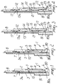
- Figure 5 is a schematic view, projected onto a plane, of the set of slider actuation cams in the second embodiment, illustrating the path of the heels of the slider when the corresponding needle must be prevented from knitting;
- Figure 6 is a schematic view, projected onto a plane, of the set of slider actuation cams in the second embodiment, illustrating the path of the heels of the slider during the transfer of the corresponding needle from the lower needle cylinder to the upper needle cylinder;
- Figure 7 is a schematic view, projected onto a plane, of the set of slider actuation cams in the second embodiment, illustrating the path of the heels of the slider in the actuation of the corresponding needle for producing drop stitches at two feeds of the machine.
-
- With reference to Figures 1 and 2, the slider according to the invention, in the first embodiment, generally designated by the reference numeral 1, comprises an elongated
laminar body 2 which has a firstlongitudinal side 3, meant to rest on thebottom 80a of theaxial slot 80 of theneedle cylinder 81 in which it is inserted, and a second longitudinal side 4, which lies opposite with respect to the firstlongitudinal side 3. - The slider is provided with a
first heel 5 and with asecond heel 6 which are mutually spaced along the longitudinal extension of thelaminar body 2 and run transversely to the longitudinal extension of thelaminar body 2 on the second side 4. - According to the invention, the
first heel 5 is arranged on a portion of thelaminar body 2 which can move with respect to the remaining part of thelaminar body 2 in a direction which has a component which is transverse with respect to the longitudinal extension of the laminar body in order to allow the transfer of thefirst heel 5 from an inactive position to an active position or viceversa. In the active position, thefirst heel 5 is spaced from thefirst side 3 of thelaminar body 2 more than in the inactive position. - Proximate to one of its longitudinal ends, the
laminar body 2 is provided, on its firstlongitudinal side 3, withmeans 7 for engaging theneedle 8 that is located in thesame slot 80 of the lower orupper needle cylinder 81. - Said engagement means 7 are constituted by a hook which is provided at a
suitable seat 3a which is formed starting from a longitudinal end of thelaminar body 2 and in which it is possible to accommodate the lower or upper portion of theneedle 8 depending on whether the slider is in the lower needle cylinder or in the upper needle cylinder. - The
first heel 5 is preferably constituted by the heel that lies closest to the longitudinal end of thelaminar body 2 which can engage theneedle 8. - In the first embodiment, shown in Figures 1 and 2, the
first heel 5 is associated, preferably monolithically, with aportion 9 of thelaminar body 2 which can flex elastically on the plane of arrangement of thelaminar body 2 with respect to the remaining part of thelaminar body 2. - More particularly, the
portion 9 is preferably formed monolithically with the remaining part of thelaminar body 2 and extends from it starting from a region which is proximate to the longitudinal end of thelaminar body 2 that lies opposite with respect to the end of said body that can engage theneedle 8. - The
second heel 6, located proximate to the longitudinal end of thelaminar body 2 that lies opposite the end that can engage theneedle 8, is preferably rigidly coupled to the remaining part of thelaminar body 2. - The
portion 9 has, on the opposite side with respect to thefirst heel 5, aresting region 10 which can be engaged against the remaining part of thelaminar body 2 in the flexing of theportion 9, so as to delimit the movement of thefirst heel 5 transversely to the longitudinal extension of thelaminar body 2 in its transfer from the active position to the inactive position, as shown in particular in Figure 2. - The slider according to the invention, in the second embodiment, shown in particular in Figures 3 and 4 and generally designated by the reference numeral 11, also comprises an elongated
laminar body 12 which has a firstlongitudinal side 13 which is meant to rest against thebottom 80a of theaxial slot 80 of the lower orupper needle cylinder 81, in which it is to be accommodated, and a secondlongitudinal side 14 which lies opposite the firstlongitudinal side 13. - In this embodiment also, the slider 11 is provided, proximate to one of its longitudinal ends, with
means 17 for engagement with aneedle 8. - Said engagement means 17 are constituted, as in the first embodiment, by a hook which can engage the lower or upper tip of the
needle 8 and is formed in asuitable seat 13a which is provided on theside 13 of thelaminar body 12 starting from its longitudinal end which is meant to be directed toward theneedle 8. Theseat 13a is meant to receive the lower portion or the upper portion of theneedle 8, depending on whether the slider is accommodated in the lower needle cylinder or in the upper needle cylinder. - The
laminar body 12 is provided with afirst heel 15 and with asecond heel 16 which run transversely to the longitudinal extension of thelaminar body 2 on the secondlongitudinal side 14. - The
second heel 16, located proximate to the longitudinal end of thelaminar body 12 that lies opposite the end that can engage theneedle 8, is preferably rigidly coupled to the remaining part of thelaminar body 12. - In this embodiment, the
first heel 15 is fitted on aportion 19 which can oscillate with respect to the remaining part of thelaminar body 12 in order to allow the transfer of thefirst heel 15 from an inactive position, in which it is close to thesecond side 13, to an active position, in which it is further spaced from the firstlongitudinal side 13 than in the inactive position, or viceversa. - Preferably, in this embodiment also the
first heel 15 of the twoheels laminar body 12 that can engage theneedle 8. - The oscillating
portion 19 is pivoted to the remaining part of thelaminar body 12 at an intermediate portion. The pivoting can be achieved, as shown, by means of a particular geometric configuration of the sides of theportion 19 and of the remaining part of thelaminar body 12 which are in mutual contact. - The
first heel 15 is located proximate to the end of the oscillatingportion 19 that lies closest to the end of thelaminar body 12 that can engage theneedle 8, and proximate to the other end of the oscillatingportion 19, which lies proximate to thesecond heel 16, anactuation lug 20 is provided which can be contacted to produce the oscillation of the oscillatingportion 19 in the transfer of thefirst heel 15 from the inactive position to the active position, as will become apparent hereinafter. - The
laminar body 12 of the slider, in the second embodiment, is provided with means for delimiting the oscillation angle of the oscillatingportion 19 with respect to the remaining part of thelaminar body 12. - Said delimiting means comprise a
seat 21 which is formed on the secondlongitudinal side 14 of thelaminar body 12; the oscillatingportion 19 is arranged in saidseat 21. Theseat 21 is delimited, along a direction which is parallel to the longitudinal extension of thelaminar body 12, by two sides located proximate to the ends of the oscillatingportion 19. On these two sides there areshoulders portion 19 when theheel 15 is moved into the active position and by the other end of the oscillatingportion 19 when thefirst heel 15 is moved into the inactive position, thus limiting the breadth of the oscillation allowed to the oscillatingportion 19. - In the first embodiment and in the second embodiment, when the
first heel 15 is in the active position it protrudes from theslot 80 of theneedle cylinder 81 and can engage at least some of the slider actuation cams that surround the needle cylinder and will be described in greater detail hereinafter, whereas when it is in the inactive position it is recessed in theslot 80 of the needle cylinder so as to avoid engaging said cams. - When the
first heel 15 is in the active position, theactuation lug 20 is located inside theslot 80, whereas when thefirst heel 15 is in the inactive position said lug protrudes from theslot 80 and can engage at least some of the slider actuation cams that face the needle cylinder and will be described in greater detail hereinafter. - The operation of the slider according to the invention is now described with reference to Figures 5, 6 and 7, which illustrate, merely by way of example, a possible configuration of the slider actuation cam set as regards the
lower needle cylinder 81. - As shown in these figures, the cams comprise a fixed
upper cam 30 which has, along its lower edge, regions designated by thereference numerals 31 to 36 which are shaped like an inclined plane and can be contacted by thefirst heel 15. Said regions 31-36 produce the transfer of saidheel 15 from the active position to the inactive position or allow its transfer from the inactive position to the active position. - The actuation cams for the
first heel 15 further comprise afirst lifting cam 37, two mutually opposite lowering cams, designated by thereference numerals cam 40, which is provided at a second feed or drop of the machine. The actuation cams for thefirst heel 15 are completed by twolifting cams cam 40. - The actuation cams for the
second heel 16 comprise a fixedcam 50 which runs entirely around the needle cylinder and further cams which are designated by thereference numerals 51 to 54. - In addition to the cams, around the needle cylinders there are suitable guiding elements which are arranged at a level which is adapted to make contact with the
actuation lug 20 in order to produce the oscillation of the oscillatingportion 19 and therefore produce the transfer of thefirst heel 15 from the inactive position to the active position. In Figures 5, 6 and 7, said guiding element have been designated by thereference numerals - In Figures 5, 6 and 7, the
first heel 15 is represented by a rectangle which is black when thefirst heel 15 is in the active position and is instead white when saidheel 15 is in the inactive position. The same rule has been adopted for theactuation lug 20, which is represented by a black rectangle when it protrudes from the needle cylinder and by a white rectangle when it is instead recessed in theslot 80 of the needle cylinder. - Figure 5 illustrates the path followed by the
heels actuation lug 20 of the slider 11 when thecorresponding needle 8 must be excluded from knitting at the two feeds of the machine; the movement of the slider 11 with respect to the set of cams for its actuation is designated by thearrow 60. - In this operating condition, the
first heel 15 is in the inactive position. In this condition, the slider 11 is not moved along the correspondingslot 80 of theneedle cylinder 81 in which it is inserted and thefirst heel 15 can move without interference beyond thecams - It should be observed that due to this fact the
cam 38, which can usually move in a radial direction with respect to the needle cylinder, can be provided as a fixed cam and the loweringcams - It should also be observed that directly ahead of the
cam 40 and of thecam 39 in thedirection 60 is not necessary to provide lowering cams in order to move thefirst heel 15 below the lower edge of said loweringcams needle 8 associated with the slider. - In the transfer of the needle from the lower cylinder to the upper cylinder, shown in Figure 6, in which the direction of the movement of the slider with respect to the cams has been indicated by the
arrow 61, thefirst heel 15 is initially, i.e., starting from the right side of Figure 6, in the active position. The slider is lifted by other elements, constituted for example by selectors which are present in thesame slot 80 below said slider, and is then lowered by thecam 30. - The slider is then raised by means of the selector or of other underlying elements and the
first heel 15 engages the inclined-plane region 31 of thecam 30 that produces the transfer of theheel 16 from the active position to the inactive position. In this position, the slider, by means of other cams of a known type which are not described further for the sake of simplicity, disengages with itshook 7 from the lower tip of the needle which is engaged by the slider arranged in the upper cylinder. Then theactuation lug 20 engages against the guidingelement 72, which produces the transfer of the first heel to the active position. Thefirst heel 15 then engages a descending portion of thecam 30 which produces the lowering of the slider. Thefirst heel 15 engages theportion 34 of thecam 30 that returns thefirst heel 15 to the inactive position. Said Figure 6 illustrates the further lifting of the slider in the lower cylinder, directly ahead of the feed served by the loweringcam 40, in the direction indicated by thearrow 61, in order to open the tab of the needle that has been transferred into the upper needle cylinder. After this further lifting, theactuation lug 20 is contacted by the guidingelement 74, which again causes the transfer of thefirst heel 15 into the active position, so that by engaging another descending portion of thecam 30 it produces the lowering of the slider. - Figure 7 illustrates the path of the heels of the slider during the production of drop stitches with the needle associated therewith at the two feeds of the machine.
- Ahead of the feed proximate to which the lowering
cams arrow 62, the slider is lifted by the corresponding selector or other underlying element, whereas thefirst heel 15 is in the inactive position due to the contact of said heel with thecam 37. - As a consequence of the engagement of the
actuation lug 20 with thecam 54, thefirst heel 15 is moved into the active position and, after the needle associated with the slider has engaged the thread at the feed being considered, thefirst heel 15 engages the loweringcam 39, which produces the lowering of the slider and therefore the retraction of the associatedneedle 8 into the lower needle cylinder in order to form new loops, lowering the previously formed loops. - The slider is then lifted again by the selector or other underlying element and is moved to a level which allows the
needle 8 associated therewith to engage the thread at the next feed. Due to this lifting, the previously formed loops are lowered onto the shank of the needle. - Then the
first heel 15, which is still in the active position, engages the loweringcam 40, which forms new loops and lowers the previously formed loops. - Downstream of the feed served by the lowering
cam 40, thefirst heel 15 again engages thecam 37, which produces the transfer of thefirst heel 15 into the inactive position, and the cycle resumes as already described. - It should be observed that in this knitting process also the
first heel 15 passes without any problem beyond the loweringcam 38, since saidheel 15 is in the inactive position. - Although the operation of the slider according to the invention has been described with reference to its use in the lower needle cylinder of a two-feed machine, it is understood that the slider according to the invention can also be used in the upper needle cylinder and in machines having a different number of feeds.
- In practice it has been observed that the slider according to the invention fully achieves the intended aim, since it allows to considerably simplify the slider actuation cams and to significantly reduce the number of cams that can move in a radial direction with respect to the needle cylinders.
- The slider thus conceived is susceptible of numerous modifications and variations, all of which are within the scope of the inventive concept; all the details may also be replaced with other technically equivalent elements.
- In practice, the materials employed, as well as the dimensions, may be any according to requirements and to the state of the art.
- The disclosures in Italian Patent Application No. MI98A002645 from which this application claims priority are incorporated herein by reference.
- Where technical features mentioned in any claim are followed by reference signs, those reference signs have been included for the sole purpose of increasing the intelligibility of the claims and accordingly, such reference signs do not have any limiting effect on the interpretation of each element identified by way of example by such reference signs.
Claims (8)
- A slider for double-cylinder circular hosiery knitting machines, comprising an elongated laminar body (2,12) which has a first longitudinal side (3,13) adapted to be rested on the bottom (80a) of an axial slot (80) formed in the curved surface of the lower needle cylinder (81) or in the curved surface of the upper needle cylinder (81) and at least two heels (5,6,15,16) which protrude transversely to the longitudinal extension of said laminar body (2,12) on a second longitudinal side (4,14) of the laminar body (2,12) which lies opposite said first side (3,13); said laminar body (2,12) having, proximate to one of its longitudinal ends, means for engagement (7,17) with a needle (8), characterized in that a first one (5,15) of said two heels is arranged on a portion (9,19) of said laminar body (2,12) which can move with respect to the remaining part of said laminar body (2,12) in a direction which has a component which is transverse with respect to the longitudinal extension of said laminar body (2,12) for the transfer of said first heel (5,15) from an inactive position to an active position, or viceversa; said first heel (5,15) being spaced from said first side (3,13) more in said active position than in said inactive position.
- The slider according to claim 1, characterized in that the second one (6) of said two heels is rigidly coupled to said remaining part of the laminar body (2).
- The slider according to claim 1, characterized in that said first heel (5,15) is constituted by the one of said two heels that lies closest to the end of said laminar body (2,12) provided with said means (7,17) for engaging the needle (8).
- The slider according to one or more of the preceding claims, characterized in that said first heel (5) is arranged on a portion (9) which can flex elastically, on the plane of arrangement of said laminar body (2), with respect to the remaining part of said laminar body (2).
- The slider according to one or more of the preceding claims, characterized in that said first heel (15) is arranged on a portion (19) which oscillates on the plane of arrangement of said laminar body (12) with respect to the remaining part of said laminar body (12).
- The slider according to one or more of the preceding claims, characterized in that said oscillating portion (19) is arranged in a seat (21) which is formed in said second side (14) of said laminar body (12), means (22,23) being provided for delimiting the oscillation angle of said oscillating portion (19) with respect to the remaining part of said laminar body (12).
- The slider according to one or more of the preceding claims, characterized in that said oscillating portion (19) has, on its side that bears said first heel (15), in a region which is spaced on the opposite side with respect to said first heel (15) relative to the fulcrum of said oscillating portion, an actuation lug (20) which can be contacted in order to produce the oscillation of said oscillating portion (19) for the transfer of said first heel (15) from said inactive position to said active position.
- The slider according to one or more of the preceding claims, characterized in that said first heel (15) is arranged proximate to the end of said oscillating portion (19) which lies closest to the end of said laminar body (12) that can engage the needle (8), said actuation lug (20) being arranged proximate to the end of said oscillating portion (19) that lies proximate to said second heel (16).
Applications Claiming Priority (2)
| Application Number | Priority Date | Filing Date | Title |
|---|---|---|---|
| IT1998MI002645A IT1303828B1 (en) | 1998-12-09 | 1998-12-09 | TRANSFER PLATINUM OR SLIDER FOR CIRCULAR MACHINERY OR DOUBLE CYLINDER FOOTWEAR. |
| ITMI982645 | 1998-12-09 |
Publications (2)
| Publication Number | Publication Date |
|---|---|
| EP1010790A2 true EP1010790A2 (en) | 2000-06-21 |
| EP1010790A3 EP1010790A3 (en) | 2001-05-23 |
Family
ID=11381199
Family Applications (1)
| Application Number | Title | Priority Date | Filing Date |
|---|---|---|---|
| EP99123961A Withdrawn EP1010790A3 (en) | 1998-12-09 | 1999-12-06 | Slider for double-cylinder circular knitting machines |
Country Status (6)
| Country | Link |
|---|---|
| US (1) | US6220061B1 (en) |
| EP (1) | EP1010790A3 (en) |
| JP (1) | JP2000170062A (en) |
| KR (1) | KR20000048037A (en) |
| CN (1) | CN1256329A (en) |
| IT (1) | IT1303828B1 (en) |
Cited By (4)
| Publication number | Priority date | Publication date | Assignee | Title |
|---|---|---|---|---|
| WO2007112915A1 (en) * | 2006-03-31 | 2007-10-11 | Lonati S.P.A. | Double-cylinder circular knitting machine for hosiery or other knitted articles |
| WO2007113649A1 (en) * | 2006-03-31 | 2007-10-11 | Lonati S.P.A. | Circular knitting machine for hosiery or the like |
| WO2007113659A2 (en) * | 2006-03-31 | 2007-10-11 | Lonati S.P.A. | Circular knitting machine for hosiery or the like |
| ITUB20155479A1 (en) * | 2015-11-11 | 2017-05-11 | Lonati Spa | PROCEDURE FOR THE PREPARATION OF A TUBULAR MANUFACTURE OF THE SOCK TYPE OR SIMILAR TO THE AUTOMATED COLLECTION AT THE END OF ITS FORMATION ON A CIRCULAR DOUBLE CYLINDER MACHINE WITH AT LEAST A FEEDING OR FALL AND A DOUBLE CYLINDER CIRCULAR MACHINE FOR ITS EXECUTION. |
Families Citing this family (5)
| Publication number | Priority date | Publication date | Assignee | Title |
|---|---|---|---|---|
| ITMI20060637A1 (en) * | 2006-03-31 | 2007-10-01 | Matec Spa | CIRCULAR MACHINE FOR KNITWEAR OR FOOTWEAR OR SIMILAR DOUBLE CYLINDER |
| ITMI20060628A1 (en) * | 2006-03-31 | 2007-10-01 | Matec Spa | CIRCULAR MACHINE FOR KNITWEAR OR FOOTWEAR OR SIMILAR DOUBLE CYLINDER |
| CZ2007107A3 (en) * | 2007-02-12 | 2008-08-20 | Golden Lady Company S.P.A. | Needle mechanism |
| CN106087228A (en) * | 2016-08-22 | 2016-11-09 | 浙江华诗秀纺织有限公司 | A kind of circular knitting machine to needle braiding structure |
| CN110512347B (en) * | 2019-04-10 | 2020-12-22 | 浙江叶晓机械科技有限公司 | Weaving method of double-needle-cylinder loom |
Citations (7)
| Publication number | Priority date | Publication date | Assignee | Title |
|---|---|---|---|---|
| FR1595574A (en) * | 1967-08-02 | 1970-06-15 | ||
| US3678710A (en) * | 1969-02-25 | 1972-07-25 | Bentley Mach Dev Co | Needle operating means in knitting machines |
| FR2375368A1 (en) * | 1976-12-23 | 1978-07-21 | Dubied & Cie Sa E | Knitting needle - has upper and lower wires connected to support upper butt and slide in needle bed groove |
| GB2099463A (en) * | 1981-05-28 | 1982-12-08 | Mecmor Spa | Cylinder and dial circular knitting machine |
| US5367893A (en) * | 1992-02-21 | 1994-11-29 | Uniplet A.S. | Selecting device with swingable selecting jack |
| EP0677605A1 (en) * | 1994-04-15 | 1995-10-18 | MATEC S.r.l. | Selection device for an elastic selector for needles in a circular knitting machine |
| EP0878572A2 (en) * | 1997-05-14 | 1998-11-18 | Groz-Beckert Kommanditgesellschaft | Knitting tool, for instance selection sinker or needle |
Family Cites Families (3)
| Publication number | Priority date | Publication date | Assignee | Title |
|---|---|---|---|---|
| US4073163A (en) * | 1976-11-08 | 1978-02-14 | Francesco Lonati | Circular knitting machine |
| IT1146698B (en) * | 1981-09-10 | 1986-11-12 | Savio Spa | PROCESSING PROCESS WITH CIRCULAR KNITTING MACHINES AND CIRCULAR MACHINES ADOPTING THIS PROCEDURE |
| CZ280577B6 (en) * | 1991-12-30 | 1996-02-14 | Uniplet, A.S. | Circular knitting machine |
-
1998
- 1998-12-09 IT IT1998MI002645A patent/IT1303828B1/en active
-
1999
- 1999-12-03 US US09/454,440 patent/US6220061B1/en not_active Expired - Fee Related
- 1999-12-06 EP EP99123961A patent/EP1010790A3/en not_active Withdrawn
- 1999-12-09 JP JP11350030A patent/JP2000170062A/en not_active Withdrawn
- 1999-12-09 CN CN99126132A patent/CN1256329A/en active Pending
- 1999-12-09 KR KR1019990056189A patent/KR20000048037A/en not_active Application Discontinuation
Patent Citations (7)
| Publication number | Priority date | Publication date | Assignee | Title |
|---|---|---|---|---|
| FR1595574A (en) * | 1967-08-02 | 1970-06-15 | ||
| US3678710A (en) * | 1969-02-25 | 1972-07-25 | Bentley Mach Dev Co | Needle operating means in knitting machines |
| FR2375368A1 (en) * | 1976-12-23 | 1978-07-21 | Dubied & Cie Sa E | Knitting needle - has upper and lower wires connected to support upper butt and slide in needle bed groove |
| GB2099463A (en) * | 1981-05-28 | 1982-12-08 | Mecmor Spa | Cylinder and dial circular knitting machine |
| US5367893A (en) * | 1992-02-21 | 1994-11-29 | Uniplet A.S. | Selecting device with swingable selecting jack |
| EP0677605A1 (en) * | 1994-04-15 | 1995-10-18 | MATEC S.r.l. | Selection device for an elastic selector for needles in a circular knitting machine |
| EP0878572A2 (en) * | 1997-05-14 | 1998-11-18 | Groz-Beckert Kommanditgesellschaft | Knitting tool, for instance selection sinker or needle |
Cited By (16)
| Publication number | Priority date | Publication date | Assignee | Title |
|---|---|---|---|---|
| WO2007112915A1 (en) * | 2006-03-31 | 2007-10-11 | Lonati S.P.A. | Double-cylinder circular knitting machine for hosiery or other knitted articles |
| WO2007113649A1 (en) * | 2006-03-31 | 2007-10-11 | Lonati S.P.A. | Circular knitting machine for hosiery or the like |
| WO2007113659A2 (en) * | 2006-03-31 | 2007-10-11 | Lonati S.P.A. | Circular knitting machine for hosiery or the like |
| WO2007113662A2 (en) * | 2006-03-31 | 2007-10-11 | Lonati S.P.A. | Circular knitting machine for hosiery or the like |
| WO2007113662A3 (en) * | 2006-03-31 | 2007-11-29 | Lonati Spa | Circular knitting machine for hosiery or the like |
| WO2007113659A3 (en) * | 2006-03-31 | 2008-02-14 | Lonati Spa | Circular knitting machine for hosiery or the like |
| US7685845B2 (en) | 2006-03-31 | 2010-03-30 | Lonati S.P.A. | Circular knitting machine for hosiery or the like |
| US7739889B2 (en) | 2006-03-31 | 2010-06-22 | Lonati S.P.A. | Circular knitting machine for hosiery or the like |
| US7765836B2 (en) | 2006-03-31 | 2010-08-03 | Lonati S.P.A. | Circular knitting machine for hosiery or the like |
| KR101368303B1 (en) * | 2006-03-31 | 2014-03-12 | 로나티 에스.피.에이. | Double-cylinder circular knitting machine for hosiery or other knitted articles |
| ITUB20155479A1 (en) * | 2015-11-11 | 2017-05-11 | Lonati Spa | PROCEDURE FOR THE PREPARATION OF A TUBULAR MANUFACTURE OF THE SOCK TYPE OR SIMILAR TO THE AUTOMATED COLLECTION AT THE END OF ITS FORMATION ON A CIRCULAR DOUBLE CYLINDER MACHINE WITH AT LEAST A FEEDING OR FALL AND A DOUBLE CYLINDER CIRCULAR MACHINE FOR ITS EXECUTION. |
| WO2017080931A1 (en) * | 2015-11-11 | 2017-05-18 | Lonati S.P.A. | Method for preparing a tubular article, such as a sock or the like, for automated pickup at the end of its forming on a double cylinder circular machine with at least one feed or drop, and double cylinder circular machine for the execution thereof |
| KR20180081046A (en) * | 2015-11-11 | 2018-07-13 | 로나티 에스.피.에이. | A method for preparing a tubular article for automated pick-up after the formation of a tubular article such as a sock or the like in a dual-cylinder circular machine having at least one feed or drop section, and a dual cylinder circular machine |
| KR102087311B1 (en) | 2015-11-11 | 2020-04-27 | 로나티 에스.피.에이. | A method for preparing a tubular article for automated pick-up after the formation of the tubular article, such as a sock, in a dual-cylinder circular machine having at least one supply or drop, and a double-cylinder circular machine for carrying out the method |
| US10718075B2 (en) | 2015-11-11 | 2020-07-21 | Lonati S.P.A. | Method for preparing a tubular article, such as a sock or the like, for automated pickup at the end of its forming on a double cylinder circular machine with at least one feed or drop, and double cylinder circular machine for the execution thereof |
| EA036310B1 (en) * | 2015-11-11 | 2020-10-26 | ЛОНАТИ С.п.А. | Method for preparing a tubular article, such as a sock, for automated pickup at the end of its forming on a double cylinder circular knitting machine, and double cylinder circular knitting machine for the execution thereof |
Also Published As
| Publication number | Publication date |
|---|---|
| JP2000170062A (en) | 2000-06-20 |
| KR20000048037A (en) | 2000-07-25 |
| CN1256329A (en) | 2000-06-14 |
| EP1010790A3 (en) | 2001-05-23 |
| US6220061B1 (en) | 2001-04-24 |
| ITMI982645A1 (en) | 2000-06-09 |
| IT1303828B1 (en) | 2001-02-23 |
Similar Documents
| Publication | Publication Date | Title |
|---|---|---|
| US7739889B2 (en) | Circular knitting machine for hosiery or the like | |
| US6220061B1 (en) | Slider for double-cylinder circular knitting machines | |
| US7765836B2 (en) | Circular knitting machine for hosiery or the like | |
| US6609395B2 (en) | Double-cylinder circular stocking knitting machine with structurally highly simplified cam box | |
| EP0683257B1 (en) | Circular knitting machine with knitting retention sinkers | |
| US2313642A (en) | Circular independent needle knitting machine | |
| US3335581A (en) | Cam means for circular knitting machines | |
| US5335518A (en) | Circular knitting machine for manufacturing socks, stockings and the like, with device for producing patterns with toweling stitches | |
| US5960645A (en) | Device for selecting needles in circular stocking knitting machines | |
| US7765834B2 (en) | Double-cylinder circular knitting machine for hosiery or other knitted articles | |
| EP0225502B1 (en) | Twin-cylinder circular knitting machine with a perfected device for actuating the transfer sinker | |
| US2385056A (en) | Circular knitting machine | |
| US3442097A (en) | Device for displacing needles for circular knitting machines | |
| US6257026B1 (en) | Needle control device for stocking knitting machines | |
| EP0962569A2 (en) | Highly versatile circular knitting machine for hosiery and the like with multiple drops or feeds | |
| US3246486A (en) | Pattern means for circular knitting machines | |
| EP0960966B1 (en) | Method and apparatus for simultaneously feeding at least two yarns in double-cylinder circular knitting machines | |
| CZ442399A3 (en) | Sinker for double-cylinder knitting machines for producing stockings | |
| US2809507A (en) | Stitch cam for circular knitting machines | |
| US1534785A (en) | Mechanism for producing openwork on knitting machines | |
| US4233823A (en) | Double-cylinder circular knitting machine | |
| US3180114A (en) | Pattern means for knitting machines | |
| ITMI982647A1 (en) | CIRCULAR MACHINE FOR KNITWEAR OR DOUBLE CYLINDER FOOTWEAR, HIGHLY SIMPLE STRUCTURAL SIMPLICITY. | |
| GB909036A (en) | Improvements in circular knitting machine for hosiery (stockings) operating with bearded needles | |
| US1942816A (en) | Knitting machine |
Legal Events
| Date | Code | Title | Description |
|---|---|---|---|
| PUAI | Public reference made under article 153(3) epc to a published international application that has entered the european phase |
Free format text: ORIGINAL CODE: 0009012 |
|
| AK | Designated contracting states |
Kind code of ref document: A2 Designated state(s): DE FR GB IT |
|
| AX | Request for extension of the european patent |
Free format text: AL;LT;LV;MK;RO;SI |
|
| PUAL | Search report despatched |
Free format text: ORIGINAL CODE: 0009013 |
|
| AK | Designated contracting states |
Kind code of ref document: A3 Designated state(s): AT BE CH CY DE DK ES FI FR GB GR IE IT LI LU MC NL PT SE |
|
| AX | Request for extension of the european patent |
Free format text: AL;LT;LV;MK;RO;SI |
|
| RIC1 | Information provided on ipc code assigned before grant |
Free format text: 7D 04B 9/10 A, 7D 04B 15/68 B |
|
| 17P | Request for examination filed |
Effective date: 20011122 |
|
| AKX | Designation fees paid |
Free format text: DE FR GB IT |
|
| STAA | Information on the status of an ep patent application or granted ep patent |
Free format text: STATUS: THE APPLICATION HAS BEEN WITHDRAWN |
|
| 18W | Application withdrawn |
Effective date: 20021209 |