EP1010660B1 - Winding device for elevator - Google Patents
Winding device for elevator Download PDFInfo
- Publication number
- EP1010660B1 EP1010660B1 EP97954869A EP97954869A EP1010660B1 EP 1010660 B1 EP1010660 B1 EP 1010660B1 EP 97954869 A EP97954869 A EP 97954869A EP 97954869 A EP97954869 A EP 97954869A EP 1010660 B1 EP1010660 B1 EP 1010660B1
- Authority
- EP
- European Patent Office
- Prior art keywords
- magnetic pole
- detector
- drive
- rotation
- field
- Prior art date
- Legal status (The legal status is an assumption and is not a legal conclusion. Google has not performed a legal analysis and makes no representation as to the accuracy of the status listed.)
- Expired - Lifetime
Links
Images


Classifications
-
- H—ELECTRICITY
- H02—GENERATION; CONVERSION OR DISTRIBUTION OF ELECTRIC POWER
- H02K—DYNAMO-ELECTRIC MACHINES
- H02K29/00—Motors or generators having non-mechanical commutating devices, e.g. discharge tubes or semiconductor devices
- H02K29/06—Motors or generators having non-mechanical commutating devices, e.g. discharge tubes or semiconductor devices with position sensing devices
- H02K29/08—Motors or generators having non-mechanical commutating devices, e.g. discharge tubes or semiconductor devices with position sensing devices using magnetic effect devices, e.g. Hall-plates, magneto-resistors
-
- B—PERFORMING OPERATIONS; TRANSPORTING
- B66—HOISTING; LIFTING; HAULING
- B66B—ELEVATORS; ESCALATORS OR MOVING WALKWAYS
- B66B1/00—Control systems of elevators in general
- B66B1/34—Details, e.g. call counting devices, data transmission from car to control system, devices giving information to the control system
- B66B1/3492—Position or motion detectors or driving means for the detector
-
- B—PERFORMING OPERATIONS; TRANSPORTING
- B66—HOISTING; LIFTING; HAULING
- B66B—ELEVATORS; ESCALATORS OR MOVING WALKWAYS
- B66B11/00—Main component parts of lifts in, or associated with, buildings or other structures
- B66B11/04—Driving gear ; Details thereof, e.g. seals
- B66B11/08—Driving gear ; Details thereof, e.g. seals with hoisting rope or cable operated by frictional engagement with a winding drum or sheave
-
- H—ELECTRICITY
- H02—GENERATION; CONVERSION OR DISTRIBUTION OF ELECTRIC POWER
- H02K—DYNAMO-ELECTRIC MACHINES
- H02K7/00—Arrangements for handling mechanical energy structurally associated with dynamo-electric machines, e.g. structural association with mechanical driving motors or auxiliary dynamo-electric machines
- H02K7/10—Structural association with clutches, brakes, gears, pulleys or mechanical starters
- H02K7/1004—Structural association with clutches, brakes, gears, pulleys or mechanical starters with pulleys
- H02K7/1012—Machine arranged inside the pulley
- H02K7/1016—Machine of the outer rotor type
-
- H—ELECTRICITY
- H02—GENERATION; CONVERSION OR DISTRIBUTION OF ELECTRIC POWER
- H02K—DYNAMO-ELECTRIC MACHINES
- H02K7/00—Arrangements for handling mechanical energy structurally associated with dynamo-electric machines, e.g. structural association with mechanical driving motors or auxiliary dynamo-electric machines
- H02K7/14—Structural association with mechanical loads, e.g. with hand-held machine tools or fans
Definitions
- the present invention relates to an elevator apparatus, and more particularly to a drive machine for elevators which employs an outer rotor motor.
- Figs. 11 and 12 show a conventional elevator apparatus disclosed in, for example, Japanese Unexamined Patent Publication No. 7-117957 .
- the disclosed elevator apparatus is of the traction sheave type wherein a main cable is wound over a drive sheave, and a cage and a counterweight are moved up and down in opposite directions.
- the elevator apparatus employs, as a winder, an outer rotor motor.
- Fig. 11 is a perspective view of the elevator apparatus
- Fig. 12 is an enlarged sectional view of a drive machine shown in Fig. 11 .
- Numeral 1 is an elevator pit
- 2 is a cage
- 3 is a cage guide rail vertically provided in pair within the elevator pit 1 for guiding both sides of the cage 2 so that the cage moves up and down along a predetermined path
- 4 is a counterweight
- 5 is a counterweight guide rail vertically provided in pair within the elevator pit 1 for guiding both sides of the counterweight 4 so that the counterweight moves up and down along a predetermined path
- 6 is a braking device associated with the counterweight 4 and tightly pressed against the counterweight guide rails 5 for applying a brake as the occasion requires.
- Numeral 7 denotes a support beam provided at the top of the elevator pit 1
- 8 denotes a winder comprising an outer rotor motor provided at the top of the elevator pit 1.
- the winder 8 mainly comprises a stationary shaft 9 having opposite ends supported by and fixed to the support beams 7, an armature iron-core 11 fixed to the shaft 9 and having armature coils 10 wound over the same, and a rotor 12 rotatably supported by the shaft 9 and constituting a drive sheave.
- the rotor 12 includes a field iron-core 13, a field permanent magnet 14, a drive sheave 16 having cable grooves formed in its outer periphery, and bearings 17 disposed between the rotor and the shaft 9 for rotatably supporting the former relative to the latter.
- Numeral 18 denotes an elevator main cable wound along the sheave groove 15, the main cable having one end coupled to the cage 2 and the other end coupled to the counterweight 4.
- Numeral 19 denotes a braking device associated with the rotor 12 for stopping the rotor 12.
- Numeral 20 denotes an absolute value encoder in the form of a ring.
- the absolute value encoder 20 is arranged such that it surrounds a projected flange of the rotor 12, is joined to the projected flange of the rotor 12 through a baring 21 for free rotation of the rotor 12, and is fixed through a mounting fixture 23 to an encoder holder 22 which is secured to the shaft 9.
- Numeral 24 denotes a supporting fixture provided on each of the support beams 7 on both sides for supporting the shaft 9.
- the magnetic pole position of the field permanent magnet 14 is detected by the absolute value encoder 20, and the phases of currents supplied to the armature coils 10 are controlled in accordance with the detected result. Also, the rotating speed and the rotating direction of the rotor 12 and hence the drive sheave 16 are detected by the absolute value encoder 20 in order to control the rising/lowering speed and the moving direction of the cage 2.
- the absolute value encoder 20 is in the ring form and arranged in a surrounding relation to the projected flange of the rotor 12, its inner diameter is so large that an inexpensive absolute value encoder, which is usually employed in general motors having rotary shafts, is not usable. This raises another problem that the absolute value encoder 20 must be a custom and expensive product.
- Still another problem is that because the magnetic pole position of the field magnet is indirectly determined by the absolute value encoder 20 surrounding the projected flange of the rotor 12, the accurate magnetic pole position of the field magnet cannot be obtained.
- the present invention has been accomplished with the view of solving the problems set forth above, and its object is to provide a drive machine for elevators which can determine the accurate magnetic pole position of a field magnet, and can facilitate maintenance work for a detecting unit to detect the magnetic pole position, the rotating speed and the rotating direction of the field magnet.
- Elevator motors comprising position detectors are also disclosed in EP-A-0631970 , WO96/06793 and EP0706258 .
- the present invention provides a drive machine for elevators, comprising:
- the field magnet comprises a permanent magnet.
- the field magnetic pole detector comprises a magnetic sensor attached to the stationary side in a close and facing relation to the field magnet.
- the drive machine for elevators further comprises a rotation detector for detecting rotation of the drive sheave with respect to the stationary shaft as a reference, and drive control means for executing drive control of the motor in accordance with results detected by the rotation detector and the field magnetic pole detector, wherein the drive control means starts up the motor in accordance with an imaginary field magnetic pole position when the magnetic pole position of the field magnet attached to the drive sheave is not known at the start-up of the elevator, and executes the drive control in accordance with the results detected by the field magnetic pole detector and the rotation detector after the field magnetic pole position has been recognized upon operation of the field magnetic pole detector.
- the drive machine for elevators further comprises a rotation detector for detecting rotation of the drive sheave with respect to the stationary shaft as a reference, detection difference calculating means for detecting the difference between the rotation of the drive sheave detected by the rotation detector and the rotation of the drive sheave detected by the field magnetic pole detector, and anomaly determining means for determining the occurrence of an anomaly when a value of the difference determined by the detection difference calculating means exceeds a predetermined value.
- the drive machine for elevators further comprises drive control means for executing drive control of the motor in accordance with results detected by the rotation detector and the field magnetic pole detector, wherein when the value of the difference determined by the detection difference calculating means does not exceed the predetermined value, the drive control means executes the control while correcting an output value of the rotation detector in accordance with the value of the difference.
- the drive machine for elevators further comprises a rotation detector for detecting rotation of the drive sheave with respect to the stationary shaft as a reference, memory means for storing an output of the rotation detector in a corresponding relation to the position detected by the field magnetic pole detector while the field magnetic pole detector is detecting the field magnetic pole position with the rotation of the drive sheave, and drive control means for executing drive control of the motor in accordance with results detected by the rotation detector and the field magnetic pole detector, wherein the drive control means utilizes values stored in the memory means for phase control of electric power supplied to the armature.
- the drive machine for elevators further comprises a rotation detector for detecting rotation of the drive sheave with respect to the stationary shaft as a reference, and drive control means for executing drive control of the motor in accordance with results detected by the rotation detector and the field magnetic pole detector, wherein the amount of change in value detected by the rotation detector is determined at the start-up of the elevator while the field magnetic pole detector detects one pair of the field magnetic poles, and the drive control means executes phase control of the motor by setting the amount of change as a reference value of a phase signal for one pair of the field magnetic poles since then.
- Fig. 1 is a sectional view showing a structure of a drive machine for elevators according to one embodiment of the present invention.
- Fig. 1 the same or corresponding parts as or to those in the conventional drive machine described above are denoted by the same symbols.
- a winder 8 mainly comprises a stationary shaft 9 having opposite ends supported by supporting fixtures 24, an armature iron-core 11 (armature) having armature coils 10 wound over the same, and a rotor 12 rotatably supported by the shaft 9 and constituting a drive sheave 16.
- armature armature
- rotor 12 rotatably supported by the shaft 9 and constituting a drive sheave 16.
- O denotes an axis of the shaft 9.
- the rotor 12 includes a field permanent magnet 14 (field magnet) disposed inside the rotor to face the armature iron-core 11, cable grooves 15 formed in an outer periphery of the rotor for receiving a main cable 18 wound over the rotor, and machined portions 30 (detected portions) in the form of recesses which are used to detect the magnetic pole position of the field permanent magnet 14. Additionally, bearings 17 are disposed between the rotor 12 and the shaft 9.
- field permanent magnet 14 field magnet
- cable grooves 15 formed in an outer periphery of the rotor for receiving a main cable 18 wound over the rotor
- machined portions 30 detected portions in the form of recesses which are used to detect the magnetic pole position of the field permanent magnet 14.
- bearings 17 are disposed between the rotor 12 and the shaft 9.
- the present invention is also similarly applicable to another type of winder wherein an iron core having coils wound around the same is disposed (not shown) in place of the permanent magnet, and electric power is supplied to the coils through a slip ring, thereby generating a magnetic field as with the permanent magnet.
- proximity switches 27 as field magnetic pole detectors for detecting the position of each machined portion 30 in the form of a recess, and a rotary encoder 29 serving as a rotation detector and including a roller 28 held pressed against the outer periphery of the rotor 12 for detecting the rotating speed and the rotating direction of the rotor 12.
- Numeral 25 denotes a mounting stand for the rotary encoder 29.
- the proximity switches 27 may be attached to the mounting stand 25, or may be attached to a dedicated mounting stand (not shown) which is provided separately.
- Fig. 2 is a sectional view taken along the line A - A of Fig. 1 , showing the positional relationship among the machined portion 30 in the form of a recess, the field permanent magnet 14, and the proximity switches 27a - 27c.
- the outer periphery of the rotor 12 is machined to have a recess (30) in a position coincident with the position of each N pole of the field permanent magnet 14 where the pole is fixed to the rotor 12, as viewed from the center LO of the rotating shaft in the radial direction, while the rotor outer periphery is not machined to have a recess in a position coincident with the position of each S pole where it is fixed to the rotor 12.
- three proximity switches 27a - 27c are mounted in a close relation to the concave and convex machined portions 30. Supposing that an angle occupied by one pair of N and S poles of the field permanent magnet 14 is ⁇ , the proximity switches 27a - 27c are arranged along the outer periphery of the rotor 12 in such positions that the interval (pitch) between the proximity switches is ⁇ /3.
- the signals from the proximity switches 27a - 27c change as shown, namely change in six combinations P1 - P6, while the rotor moves through the angle ⁇ corresponding to one pair of the concave and convex portions.
- the signals from the proximity switches 27a - 27c change in the same manner repeatedly. Since the concave and convex portions are positioned in a one-to-one relation to the magnetic poles, ⁇ is given by 360 degrees representing one cycle of the magnetic pole phase, and therefore P1 to P6 each represent a range of 60 degrees. In other words, the magnetic pole position can be determined based on the combinations in state of the signals from the proximity switches 27a - 27c with resolution of 60 degrees.
- a synchronous motor of the type employing a permanent magnet cannot start up unless the magnetic pole position of a fertil magnet is known at the time of start-up.
- the magnetic pole position can be detected with an angular range of 60 degrees. Assuming that the magnetic pole position locates at the middle of the 60-degree range, an error between the actual magnetic pole position and the measured magnetic pole position is ⁇ 30 degrees at maximum.
- the magnetic pole position can be precisely detected at that time, and current phase control can be performed with a highly-accurate magnetic pole position signal since then.
- the changing-over point between the concave and convex portions is coincident with the changing-over point between the magnetic poles, this provides such an advantage that the changing-over point between the magnetic poles can be directly read based on the signals from the proximity switches 27a - 27c.
- the rotating direction and the rotating speed of the rotor 12 are determined based on a signal from the rotary encoder 29.
- the concave and convex machined portions may be provided in any other suitable locations than the outer periphery of the rotor.
- a similar operating effect as described above can be obtained if the concave and convex machined portions are located in coincidence with the positions of the magnetic poles of the field magnet as viewed from the center of the rotating shaft in the radial direction.
- the similar operating effect can also be obtained by attaching a ring with concave and convex portions in coincidence with the magnetic pole positions rather than directly machining the rotor (drive sheave) to have the concave and convex portions.
- the proximity switches 27a - 27c serving as field magnetic pole detectors and the rotary encoder 29 serving as a rotation detector are arranged as separate components in an easily detachable manner, it is easy to carry out check and displacement in the event of failure.
- the winder can be controlled with good accuracy.
- FIG. 6 is a control block diagram of an inverter for driving the winder 8 which comprises a synchronous motor of the outer rotor type employing a permanent magnet as a field magnet. Note that an elevator control section, a position control section, etc., which are not directly related to the present invention, are omitted from the drawing.
- Numeral 43 denotes an inverter for driving the winder 8 which comprises an outer rotor motor
- 27 denotes a proximity switch for detecting the field magnetic pole position within the winder 8
- 29 denotes a rotary encoder for detecting the rotation of the winder 8 through the roller 28.
- denoted by numeral 40 is a power supply
- 41 is a converter
- 42 is a smoothing capacitor
- 2 is an elevator cage
- 4 is a counterweight.
- Numeral 45 denotes a speed detecting section for determining the speed based on a signal from the rotary encoder 29, 46 denotes a phase detecting section for determining the current phase based on a signal from the rotary encoder 29, 47 denotes a magnetic pole position detecting section for determining the magnetic pole position based on signals from the proximity switches 27, 49 denotes a speed control section for combining a speed command-and a speed feedback signal ⁇ to calculate a torque current command iq, 50 denotes a current command creating section for calculating a current command from an excitation current command id, the torque current command iq and a phase signal ⁇ , and 51 denotes a current control section for combining the current command and a current detection signal from a current sensor 44 to output a control signal to the inverter 43.
- Numeral 55 denotes memory means for storing, in a correlated manner, the current phase, i.e., the position in the field magnet, determined by the phase detecting section 46 based on the signal from the rotary encoder 29, and the magnetic pole position recognized by the magnetic pole position detecting section 47 based on the signals detected by the proximity switches 27.
- Numeral 56 denotes detection difference calculating means for determining the difference between the magnetic pole position recognized by the magnetic pole position detecting section 47 based on the signals detected by the proximity switches 27 and the magnetic pole position determined by the phase detecting section 46 based on the signal from the rotary encoder 29.
- Numeral 57 denotes anomaly determining means for generating an abnormal signal upon determining the occurrence of an anomaly if the difference or deviation in the magnetic pole position resulted from the different detectors and determined by the detection difference calculating means 56 exceeds a predetermined value.
- phase signal ⁇ A manner of determining the phase signal ⁇ will now be described with reference to Fig. 7 .
- alphabet A represents an initial state immediately after power-on, and the phase signal ⁇ is set to a phase signal ⁇ A that is determined from a combination of the signals from the three proximity switches 27 in accordance with the above-described method.
- the phase detecting section 46 counts the number of the pulses, and outputs the phase signal ⁇ after multiplying the counted number by a phase angle corresponding to one pulse.
- the current phase signal ⁇ must be coincident with the cycle of the magnetic pole position of the field magnet.
- phase signal ⁇ is reset to be coincident with 0 degree, for example, at the changing-over point from the S to N pole of the magnetic pole position signal determined based on the signals from the proximity switches 27, as shown in Fig. 7 .
- the length of one cycle of each detector signal may change due to errors in machining of the concave machined portions 30 serving as the detected portions in Embodiment 1, or errors in installation of the proximity switches 27a - 27c used in Embodiment 1 and the magnetic sensors 70a - 70c used in Embodiment 2 which serves as the field magnetic pole detectors. If the length of one cycle is shortened, for example, the phase signal ⁇ is reset to 0 degree before reaching 360 degrees. Conversely, if the length of one cycle is prolonged, the phase signal ⁇ is reset midway the succeeding cycle. This results in that the phase signal ⁇ becomes not consistent and the motor cannot rotate smoothly.
- a time period (a) in Fig. 8 is represented by a value of C2 - C1, a time period (b) by a value of C3 - C2, and a time period (c) by a value of C4 - C3.
- the amount of change in value of the phase signal ⁇ corresponding to one count of the output pulses from the rotation detector is calculated from the stored pulse counted values, and is set to be larger than in the standard time period to modify the value of the phase signal ⁇ so that one cycle completes at 360 degrees.
- the amount of change in value of the phase signal ⁇ is set to be smaller than in the standard time period to modify the value of the phase signal ⁇ so that one cycle completes at 360 degrees. Stated otherwise, as shown in Fig.
- phase signal ⁇ has the same slope for each time period in the unmodified case, the slope of the phase signal ⁇ is changed depending on the stored length of one cycle in the modified case. With such a modification, the value of the phase signal ⁇ is kept from becoming inconsistent, and smooth phase control can be achieved.
- the magnetic pole position detecting section 47 detects the changing-over point in the cycle of the magnetic poles, and assigns the successive number to each cycle from the first cycle over a full turn. At the same time, the assigned numbers and the difference in counted value of the output pulses from the rotary encoder 29 for each cycle are stored in the storage means 55. After that, the magnetic pole position detecting section 47 outputs, to the phase detecting section 46, information indicating in what number of magnetic pole cycle the winder 8 is positioned at this moment.
- the phase detecting section 46 reads the difference in counted value of the corresponding magnetic pole cycle from the storage means 55, and determines the length of the cycle. Then, in consideration of correspondence between the signal newly inputted from the rotary encoder 29 and the length of the cycle, the phase detecting section 46 modifies and calculates the phase signal ⁇ so that one cycle completes at 360 degrees. The modified phase signal ⁇ is outputted to the current command creating section 50.
- the detection difference calculating means 56 determines how far the phase signal ⁇ from the phase detecting section 46 deviates from 0 degree or 360 degrees.
- the anomaly determining means 57 sets an angle of a certain width d at the changing-over point from the S to N pole of the magnetic pole position signal from the magnetic pole position detecting section 47 as shown in Fig. 9 , and monitors whether the angle of the phase signal ⁇ from the phase detecting section 46 deviates over the angle d not, thereby outputting an abnormal signal if the deviation over the angle d occurs.
- the width of d is set to about 10 degrees in terms of phase angle, taking into account that a torque reduction should not be so increased and that a speed detection error should not be so enlarged.
- a response speed of the rotary encoder 29 is sufficiently high and a delay in operation thereof is negligible.
- the roller 28 may be abraded to cause a change of configuration over time and hence to produce an error in the phase signal ⁇ .
- the roller 28 has a diameter of 100 mm and the length of one pair of magnetic poles of the field permanent magnet 14 is exactly equal to 1/2 of the outer circumference of the roller 28, if the roller 28 is abraded 0.1 mm and the diameter is changed to 99.8 mm, the phase signal ⁇ would shift 90 degrees in terms of the magnetic pole phase after only 62.5 rotations of the roller 28.
- the 90-degree shift of the magnetic pole phase means that the torque applied to the winder 8 becomes zero.
- the number of output pulses from the rotary encoder 29 is counted (a value given by PB - PA in the drawing) for one cycle of the signal from the proximity switch 27 (indicated by the signal from 27a in the drawing), and the counted value is used as a reference value for one cycle of the magnetic pole phase in the subsequent phase calculation until the winder 8 is stopped. Since the length of one pair of magnetic poles of the field permanent magnet 14 is fixed regardless of the roller abrasion, the pulse count for one cycle of the magnetic pole phase can be correctly detected even if the roller diameter varies due to a change of configuration over time.
- a drive machine for elevators comprises a rotatable drive sheave over which a main cable for hanging an elevator cage is wound, a stationary shaft for supporting rotation of the drive sheave and bearing a load applied to the drive sheave from the main cable, a field magnet attached to the drive sheave, constituting a part of an electric motor, and comprising at least one pair of magnetic poles, an armature attached to the stationary shaft in a facing relation to the field magnet and constituting another part of the motor, and a field magnetic pole detector for detecting the predetermined magnetic pole of the field magnet rotated together with the drive sheave.
- the field magnetic pole detector capable of directly and precisely detecting the position in the field magnet, rotational angle control of the drive sheave and control of the motor can be implemented with good accuracy.
- a detected portion indicating the position of the magnetic pole disposed on the drive sheave is provided on the drive sheave in a facing relation to the field magnetic pole detector, and the position of the predetermined magnetic pole is recognized with the field magnetic pole detector detecting the detected portion.
- the detected portion comprises a convex or concave portion formed on or in the surface of the drive sheave corresponding to the position of the predetermined magnetic pole.
Abstract
Description
- The present invention relates to an elevator apparatus, and more particularly to a drive machine for elevators which employs an outer rotor motor.
-
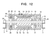
Figs. 11 and12 show a conventional elevator apparatus disclosed in, for example, Japanese Unexamined Patent Publication No.7-117957 Fig. 11 is a perspective view of the elevator apparatus, andFig. 12 is an enlarged sectional view of a drive machine shown inFig. 11 . - Referring to
Figs. 11 and12 , denoted by numeral 1 is an elevator pit, 2 is a cage, 3 is a cage guide rail vertically provided in pair within the elevator pit 1 for guiding both sides of thecage 2 so that the cage moves up and down along a predetermined path, 4 is a counterweight, 5 is a counterweight guide rail vertically provided in pair within the elevator pit 1 for guiding both sides of thecounterweight 4 so that the counterweight moves up and down along a predetermined path, and 6 is a braking device associated with thecounterweight 4 and tightly pressed against thecounterweight guide rails 5 for applying a brake as the occasion requires. Numeral 7 denotes a support beam provided at the top of theelevator pit 1, and 8 denotes a winder comprising an outer rotor motor provided at the top of the elevator pit 1. - As shown in
Fig. 12 , thewinder 8 mainly comprises astationary shaft 9 having opposite ends supported by and fixed to thesupport beams 7, an armature iron-core 11 fixed to theshaft 9 and having armature coils 10 wound over the same, and arotor 12 rotatably supported by theshaft 9 and constituting a drive sheave. - The
rotor 12 includes a field iron-core 13, a fieldpermanent magnet 14, adrive sheave 16 having cable grooves formed in its outer periphery, andbearings 17 disposed between the rotor and theshaft 9 for rotatably supporting the former relative to the latter. Numeral 18 denotes an elevator main cable wound along thesheave groove 15, the main cable having one end coupled to thecage 2 and the other end coupled to thecounterweight 4. Numeral 19 denotes a braking device associated with therotor 12 for stopping therotor 12. - Numeral 20 denotes an absolute value encoder in the form of a ring. The
absolute value encoder 20 is arranged such that it surrounds a projected flange of therotor 12, is joined to the projected flange of therotor 12 through abaring 21 for free rotation of therotor 12, and is fixed through amounting fixture 23 to anencoder holder 22 which is secured to theshaft 9. Numeral 24 denotes a supporting fixture provided on each of thesupport beams 7 on both sides for supporting theshaft 9. - In the drive machine thus constructed, the magnetic pole position of the field
permanent magnet 14 is detected by theabsolute value encoder 20, and the phases of currents supplied to thearmature coils 10 are controlled in accordance with the detected result. Also, the rotating speed and the rotating direction of therotor 12 and hence thedrive sheave 16 are detected by theabsolute value encoder 20 in order to control the rising/lowering speed and the moving direction of thecage 2. - In not only such a synchronous motor using a field permanent magnet, but also other electric motors such as the so-called three-phase induction motor, it is important to detect the rotational angle of a rotor with respect to a field magnet in a circuit driving control for any of those motors.
- The above-described conventional drive machine for elevators has problems below. Supposing, for example, that the
absolute value encoder 20 directly attached to the shaft of the winder malfunctions and has to be replaced, because theabsolute value encoder 20 is in the ring form, it is required to dismount the entirety of thewinder 8 by moving theshaft 9 upward so as to be withdrawn from the supportingfixtures 24 fixed to thesupport beams 7, thus resulting in troublesome work. In addition, when thewinder 8 is mounted at the top of the elevator pit 1, scaffolding must be temporarily built up, which renders the replacement work more troublesome. - Further, because the
absolute value encoder 20 is in the ring form and arranged in a surrounding relation to the projected flange of therotor 12, its inner diameter is so large that an inexpensive absolute value encoder, which is usually employed in general motors having rotary shafts, is not usable. This raises another problem that theabsolute value encoder 20 must be a custom and expensive product. - Still another problem is that because the magnetic pole position of the field magnet is indirectly determined by the
absolute value encoder 20 surrounding the projected flange of therotor 12, the accurate magnetic pole position of the field magnet cannot be obtained. - The present invention has been accomplished with the view of solving the problems set forth above, and its object is to provide a drive machine for elevators which can determine the accurate magnetic pole position of a field magnet, and can facilitate maintenance work for a detecting unit to detect the magnetic pole position, the rotating speed and the rotating direction of the field magnet.
- Elevator motors comprising position detectors are also disclosed in
EP-A-0631970 ,WO96/06793 EP0706258 . - The present invention provides a drive machine for elevators, comprising:
- a rotatable drive sheave over which a main cable for hanging an elevator cage is wound,
- a stationary shaft for supporting rotation of said drive sheave and bearing a load applied to said drive sheave from said main cable,
- a field magnet attached to said drive sheave, constituting a part of an electric motor, and comprising at least one pair of magnetic poles,
- an armature attached to said stationary shaft in a facing relation to said field magnet and constituting another part of said motor,
- a detected portion comprising a convex or concave portion formed on or in the surface of said drive sheave corresponding to the position of a predetermined magnetic pole for indicating the position of the predetermined magnetic pole for indicating the position of the predetermined magnetic pole, and a field magnetic pole detector disposed in a facing relation to said detected portion for detecting the position of the predetermined magnetic pole rotated together with said drive sheave.
- Preferably, the field magnet comprises a permanent magnet.
- Preferably, the field magnetic pole detector comprises a magnetic sensor attached to the stationary side in a close and facing relation to the field magnet.
- Preferably, there are at least three of the field magnetic pool detectors provided at a pitch = 1/3 of the pitch of one pair of the poles of the field magnet. Preferably, the drive machine for elevators further comprises a rotation detector for detecting rotation of the drive sheave with respect to the stationary shaft as a reference, and drive control means for executing drive control of the motor in accordance with results detected by the rotation detector and the field magnetic pole detector, wherein the drive control means starts up the motor in accordance with an imaginary field magnetic pole position when the magnetic pole position of the field magnet attached to the drive sheave is not known at the start-up of the elevator, and executes the drive control in accordance with the results detected by the field magnetic pole detector and the rotation detector after the field magnetic pole position has been recognized upon operation of the field magnetic pole detector.
- Preferably, the drive machine for elevators further comprises a rotation detector for detecting rotation of the drive sheave with respect to the stationary shaft as a reference, detection difference calculating means for detecting the difference between the rotation of the drive sheave detected by the rotation detector and the rotation of the drive sheave detected by the field magnetic pole detector, and anomaly determining means for determining the occurrence of an anomaly when a value of the difference determined by the detection difference calculating means exceeds a predetermined value.
- Preferably, the drive machine for elevators further comprises drive control means for executing drive control of the motor in accordance with results detected by the rotation detector and the field magnetic pole detector, wherein when the value of the difference determined by the detection difference calculating means does not exceed the predetermined value, the drive control means executes the control while correcting an output value of the rotation detector in accordance with the value of the difference.
- Preferably, the drive machine for elevators further comprises a rotation detector for detecting rotation of the drive sheave with respect to the stationary shaft as a reference, memory means for storing an output of the rotation detector in a corresponding relation to the position detected by the field magnetic pole detector while the field magnetic pole detector is detecting the field magnetic pole position with the rotation of the drive sheave, and drive control means for executing drive control of the motor in accordance with results detected by the rotation detector and the field magnetic pole detector, wherein the drive control means utilizes values stored in the memory means for phase control of electric power supplied to the armature.
- Preferably, the drive machine for elevators further comprises a rotation detector for detecting rotation of the drive sheave with respect to the stationary shaft as a reference, and drive control means for executing drive control of the motor in accordance with results detected by the rotation detector and the field magnetic pole detector, wherein the amount of change in value detected by the rotation detector is determined at the start-up of the elevator while the field magnetic pole detector detects one pair of the field magnetic poles, and the drive control means executes phase control of the motor by setting the amount of change as a reference value of a phase signal for one pair of the field magnetic poles since then.
-
-
Fig. 1 is a sectional view showing a structure of a drive machine for elevators according to Embodiment 1 of the present invention. -
Fig. 2 is a sectional view taken along the line A - A ofFig. 1 . -
Fig. 3 is a chart showing the correlation between the positions of proximity switches shown inFig. 2 and signals from the proximity switches. -
Fig. 6 is a block diagram showing inverter control in drive machine according toEmbodiments -
Fig. 7 is a waveform chart for explaining the operation ofEmbodiment 2 of the present invention. -
Fig. 8 is a waveform chart for explaining another operation ofEmbodiment 2 of the present invention. -
Fig. 9 is a waveform chart for explaining still another operation ofEmbodiment 2 of the present invention. -
Fig. 10 is a waveform chart for explaining the operation ofEmbodiment 3 of the present invention. -
Fig. 11 is a perspective view of a conventional elevator apparatus including a winder which comprises an outer rotor. -
Fig. 12 is a sectional view showing a structure of a conventional drive machine for elevators which comprises an outer rotor. -
Fig. 1 is a sectional view showing a structure of a drive machine for elevators according to one embodiment of the present invention. InFig. 1 , the same or corresponding parts as or to those in the conventional drive machine described above are denoted by the same symbols. - A
winder 8 mainly comprises astationary shaft 9 having opposite ends supported by supportingfixtures 24, an armature iron-core 11 (armature) havingarmature coils 10 wound over the same, and arotor 12 rotatably supported by theshaft 9 and constituting adrive sheave 16. Note that O denotes an axis of theshaft 9. - The
rotor 12 includes a field permanent magnet 14 (field magnet) disposed inside the rotor to face the armature iron-core 11,cable grooves 15 formed in an outer periphery of the rotor for receiving amain cable 18 wound over the rotor, and machined portions 30 (detected portions) in the form of recesses which are used to detect the magnetic pole position of the fieldpermanent magnet 14. Additionally,bearings 17 are disposed between therotor 12 and theshaft 9. - While the winder utilizing the
permanent magnet 14 as a field magnet is described here, the present invention is also similarly applicable to another type of winder wherein an iron core having coils wound around the same is disposed (not shown) in place of the permanent magnet, and electric power is supplied to the coils through a slip ring, thereby generating a magnetic field as with the permanent magnet. - Further, around the
winder 8, there are providedproximity switches 27 as field magnetic pole detectors for detecting the position of each machinedportion 30 in the form of a recess, and arotary encoder 29 serving as a rotation detector and including aroller 28 held pressed against the outer periphery of therotor 12 for detecting the rotating speed and the rotating direction of therotor 12. Numeral 25 denotes a mounting stand for therotary encoder 29. Theproximity switches 27 may be attached to themounting stand 25, or may be attached to a dedicated mounting stand (not shown) which is provided separately. -
Fig. 2 is a sectional view taken along the line A - A ofFig. 1 , showing the positional relationship among the machinedportion 30 in the form of a recess, the fieldpermanent magnet 14, and the proximity switches 27a - 27c. Referring toFig. 2 , the outer periphery of therotor 12 is machined to have a recess (30) in a position coincident with the position of each N pole of the fieldpermanent magnet 14 where the pole is fixed to therotor 12, as viewed from the center LO of the rotating shaft in the radial direction, while the rotor outer periphery is not machined to have a recess in a position coincident with the position of each S pole where it is fixed to therotor 12. - To detect the positions of the concave and convex
machined portions 30 formed in the outer periphery of therotor 12, threeproximity switches 27a - 27c are mounted in a close relation to the concave and convexmachined portions 30. Supposing that an angle occupied by one pair of N and S poles of the fieldpermanent magnet 14 is α, the proximity switches 27a - 27c are arranged along the outer periphery of therotor 12 in such positions that the interval (pitch) between the proximity switches is α/3. - Next, how respective signals from the proximity switches 27a - 27c change depending on their relative positions to the concave and convex
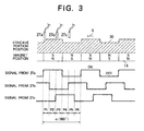
machined portions 30 will be described in conjunction withFig. 3 . For the convenience of explanation, the positions of the concave and convex portions and the magnets, and the mount positions of the proximity switches are represented in the linear form. - When the concave and convex portions are moved from the position shown in
Fig. 3 in the direction of arrow S, the signals from the proximity switches 27a - 27c change as shown, namely change in six combinations P1 - P6, while the rotor moves through the angle α corresponding to one pair of the concave and convex portions. After that, the signals from the proximity switches 27a - 27c change in the same manner repeatedly. Since the concave and convex portions are positioned in a one-to-one relation to the magnetic poles, α is given by 360 degrees representing one cycle of the magnetic pole phase, and therefore P1 to P6 each represent a range of 60 degrees. In other words, the magnetic pole position can be determined based on the combinations in state of the signals from the proximity switches 27a - 27c with resolution of 60 degrees. - As well known, a synchronous motor of the type employing a permanent magnet cannot start up unless the magnetic pole position of a fled magnet is known at the time of start-up. With the method according to this Embodiment, the magnetic pole position can be detected with an angular range of 60 degrees. Assuming that the magnetic pole position locates at the middle of the 60-degree range, an error between the actual magnetic pole position and the measured magnetic pole position is ± 30 degrees at maximum. When the synchronous motor of the type employing a permanent magnet is operated under vector control, a torque reduction of 13 % occurs at a maximum error because of cos30° = 0.87, but a sufficient torque for the start-up can be generated. Once the
rotor 12 is rotated and a level of the signal from any one of the proximity switches 27a - 27c is changed over, the magnetic pole position can be precisely detected at that time, and current phase control can be performed with a highly-accurate magnetic pole position signal since then. - When later-described drive control means for the
winder 8 in the form of a motor, shown inFig. 6 , cannot know in which position the motor locates relative to the corresponding field magnetic pole at the start-up, i.e., when it is not known how far the motor has rotated, before stopping, from the changing-over point of the magnetic pole to be detected, an imaginary position in the field magnet is introduced and phase control is performed in accordance with the imaginary position in the field magnet until the first field magnetic pole detector starts operation. By so doing, the drive sheave can be started up even if the position in the field magnet is not known at the start-up. - Further, since the changing-over point between the concave and convex portions is coincident with the changing-over point between the magnetic poles, this provides such an advantage that the changing-over point between the magnetic poles can be directly read based on the signals from the proximity switches 27a - 27c. On the other hand, the rotating direction and the rotating speed of the
rotor 12 are determined based on a signal from therotary encoder 29. - The concave and convex machined portions may be provided in any other suitable locations than the outer periphery of the rotor. A similar operating effect as described above can be obtained if the concave and convex machined portions are located in coincidence with the positions of the magnetic poles of the field magnet as viewed from the center of the rotating shaft in the radial direction. The similar operating effect can also be obtained by attaching a ring with concave and convex portions in coincidence with the magnetic pole positions rather than directly machining the rotor (drive sheave) to have the concave and convex portions.
- As described above, since the proximity switches 27a - 27c serving as field magnetic pole detectors and the
rotary encoder 29 serving as a rotation detector are arranged as separate components in an easily detachable manner, it is easy to carry out check and displacement in the event of failure. - Moreover, since the field magnetic pole position is directly detected from the concave and convex
machined portions 30 precisely corresponding to the fieldpermanent magnet 14 which provides field magnetic poles, the winder can be controlled with good accuracy. - A phase control method used in the case of detecting the rotation of the
winder 8 by therotary encoder 29 using theroller 28, and detecting the magnetic pole position by separate magnetic pole position detectors, as described in the above First and Second Embodiments, will be described below with reference toFigs. 6 and7 .Fig. 6 is a control block diagram of an inverter for driving thewinder 8 which comprises a synchronous motor of the outer rotor type employing a permanent magnet as a field magnet. Note that an elevator control section, a position control section, etc., which are not directly related to the present invention, are omitted from the drawing. - In
Fig. 6 , the same or corresponding parts as or to those in the above Embodiments are denoted by the same symbols.Numeral 43 denotes an inverter for driving thewinder 8 which comprises an outer rotor motor, 27 denotes a proximity switch for detecting the field magnetic pole position within thewinder winder 8 through theroller 28. Further, denoted bynumeral 40 is a power supply, 41 is a converter, 42 is a smoothing capacitor, 2 is an elevator cage, and 4 is a counterweight. -
Numeral 45 denotes a speed detecting section for determining the speed based on a signal from therotary encoder rotary encoder current sensor 44 to output a control signal to theinverter 43. -
Numeral 55 denotes memory means for storing, in a correlated manner, the current phase, i.e., the position in the field magnet, determined by thephase detecting section 46 based on the signal from therotary encoder 29, and the magnetic pole position recognized by the magnetic poleposition detecting section 47 based on the signals detected by the proximity switches 27.Numeral 56 denotes detection difference calculating means for determining the difference between the magnetic pole position recognized by the magnetic poleposition detecting section 47 based on the signals detected by the proximity switches 27 and the magnetic pole position determined by thephase detecting section 46 based on the signal from therotary encoder 29.Numeral 57 denotes anomaly determining means for generating an abnormal signal upon determining the occurrence of an anomaly if the difference or deviation in the magnetic pole position resulted from the different detectors and determined by the detection difference calculating means 56 exceeds a predetermined value. - A manner of determining the phase signal θ will now be described with reference to
Fig. 7 . InFig. 7 , alphabet A represents an initial state immediately after power-on, and the phase signal θ is set to a phase signal θA that is determined from a combination of the signals from the threeproximity switches 27 in accordance with the above-described method. Subsequently, when thewinder 8 is rotated and a pulse signal is outputted from therotary encoder 29 with the rotation of thewinder 8, thephase detecting section 46 counts the number of the pulses, and outputs the phase signal θ after multiplying the counted number by a phase angle corresponding to one pulse. Further, in the synchronous motor, the current phase signal θ must be coincident with the cycle of the magnetic pole position of the field magnet. - To that end, the phase signal θ is reset to be coincident with 0 degree, for example, at the changing-over point from the S to N pole of the magnetic pole position signal determined based on the signals from the proximity switches 27, as shown in
Fig. 7 . - As shown in
Fig. 8 , however, the length of one cycle of each detector signal may change due to errors in machining of the concavemachined portions 30 serving as the detected portions in Embodiment 1, or errors in installation of the proximity switches 27a - 27c used in Embodiment 1 and the magnetic sensors 70a - 70c used inEmbodiment 2 which serves as the field magnetic pole detectors. If the length of one cycle is shortened, for example, the phase signal θ is reset to 0 degree before reaching 360 degrees. Conversely, if the length of one cycle is prolonged, the phase signal θ is reset midway the succeeding cycle. This results in that the phase signal θ becomes not consistent and the motor cannot rotate smoothly. - To cope with the above-mentioned problem, the length corresponding to each cycle of the magnetic poles is stored as the difference in counted value of the output pulses from the rotation detector (rotary encoder 29) over the entire circumference of the
winder 8. Thus, a time period (a) inFig. 8 is represented by a value of C2 - C1, a time period (b) by a value of C3 - C2, and a time period (c) by a value of C4 - C3. - In a shorter time period, e.g., the time period (b), than the standard one (a), the amount of change in value of the phase signal θ corresponding to one count of the output pulses from the rotation detector is calculated from the stored pulse counted values, and is set to be larger than in the standard time period to modify the value of the phase signal θ so that one cycle completes at 360 degrees. Conversely, in a longer time period, e.g., the time period (c), than the standard one (a), the amount of change in value of the phase signal θ is set to be smaller than in the standard time period to modify the value of the phase signal θ so that one cycle completes at 360 degrees. Stated otherwise, as shown in
Fig. 8 , while the phase signal θ has the same slope for each time period in the unmodified case, the slope of the phase signal θ is changed depending on the stored length of one cycle in the modified case. With such a modification, the value of the phase signal θ is kept from becoming inconsistent, and smooth phase control can be achieved. - The operation in the above case will be described below with reference to
Fig. 6 . After thewinder 8 has started up, the magnetic poleposition detecting section 47 detects the changing-over point in the cycle of the magnetic poles, and assigns the successive number to each cycle from the first cycle over a full turn. At the same time, the assigned numbers and the difference in counted value of the output pulses from therotary encoder 29 for each cycle are stored in the storage means 55. After that, the magnetic poleposition detecting section 47 outputs, to thephase detecting section 46, information indicating in what number of magnetic pole cycle thewinder 8 is positioned at this moment. In accordance with the indicated number of magnetic pole cycle, thephase detecting section 46 reads the difference in counted value of the corresponding magnetic pole cycle from the storage means 55, and determines the length of the cycle. Then, in consideration of correspondence between the signal newly inputted from therotary encoder 29 and the length of the cycle, thephase detecting section 46 modifies and calculates the phase signal θ so that one cycle completes at 360 degrees. The modified phase signal θ is outputted to the currentcommand creating section 50. - On the other hand, because the rotation of the
winder 8 is detected by therotary encoder 29 using theroller 28, there is a possibility that slippage of the roller may occur. - The function of detecting such a slippage and the function of generating an abnormal signal will now be described with reference to
Fig. 9 . - If the rotation of the
rotary encoder 29 becomes slower than the rotation of thewinder 8 due to slippage of theroller 28 during the operation, the phase signal θ deviates by a large amount from 360 degrees at the changing-over point of the magnetic pole position signal as indicated by X inFig. 9 . In view of such a problem, at the changing-over point from the S to N pole of the magnetic pole position signal from the magnetic poleposition detecting section 47, the detection difference calculating means 56 determines how far the phase signal θ from thephase detecting section 46 deviates from 0 degree or 360 degrees. Then, the anomaly determining means 57 sets an angle of a certain width d at the changing-over point from the S to N pole of the magnetic pole position signal from the magnetic poleposition detecting section 47 as shown inFig. 9 , and monitors whether the angle of the phase signal θ from thephase detecting section 46 deviates over the angle d not, thereby outputting an abnormal signal if the deviation over the angle d occurs. The width of d is set to about 10 degrees in terms of phase angle, taking into account that a torque reduction should not be so increased and that a speed detection error should not be so enlarged. - Further, when the rotation of the
winder 8 is sped up, there also occurs an error in the magnetic pole position signal due to a delay in operation of the proximity switches 27. Since this error is proportional to the speed, the speed feedback signal ω is applied to the magnetic poleposition detecting section 47 which creates the magnetic pole position signal after compensating for the error in accordance with the speed feedback signal ω. This process increases the accuracy in detecting slippage of the roller. - On the other hand, a response speed of the
rotary encoder 29 is sufficiently high and a delay in operation thereof is negligible. - When the rotation of the
winder 8 is detected by therotary encoder 29 using theroller 28 like the above Embodiment 1, theroller 28 may be abraded to cause a change of configuration over time and hence to produce an error in the phase signal θ. Supposing, for example, that theroller 28 has a diameter of 100 mm and the length of one pair of magnetic poles of the fieldpermanent magnet 14 is exactly equal to 1/2 of the outer circumference of theroller 28, if theroller 28 is abraded 0.1 mm and the diameter is changed to 99.8 mm, the phase signal θ would shift 90 degrees in terms of the magnetic pole phase after only 62.5 rotations of theroller 28. The 90-degree shift of the magnetic pole phase means that the torque applied to thewinder 8 becomes zero. - To cope with that problem, as shown in
Fig. 10 , immediately after the start-up of thewinder 8, the number of output pulses from therotary encoder 29 is counted (a value given by PB - PA in the drawing) for one cycle of the signal from the proximity switch 27 (indicated by the signal from 27a in the drawing), and the counted value is used as a reference value for one cycle of the magnetic pole phase in the subsequent phase calculation until thewinder 8 is stopped. Since the length of one pair of magnetic poles of the fieldpermanent magnet 14 is fixed regardless of the roller abrasion, the pulse count for one cycle of the magnetic pole phase can be correctly detected even if the roller diameter varies due to a change of configuration over time. As an alternative, counting the number of pulses over several cycles and calculating an average of the counted numbers as a standard value further increases the accuracy. Such a modification can be easily implemented, for example, by adding a correctingsection 46a, which has the calculating and storing functions and the temporarily storing function required for the modified process, to thephase detector 46 shown inFig. 6 . - As described above, according to the first aspect of the present invention, a drive machine for elevators comprises a rotatable drive sheave over which a main cable for hanging an elevator cage is wound, a stationary shaft for supporting rotation of the drive sheave and bearing a load applied to the drive sheave from the main cable, a field magnet attached to the drive sheave, constituting a part of an electric motor, and comprising at least one pair of magnetic poles, an armature attached to the stationary shaft in a facing relation to the field magnet and constituting another part of the motor, and a field magnetic pole detector for detecting the predetermined magnetic pole of the field magnet rotated together with the drive sheave. With the provision of the field magnetic pole detector capable of directly and precisely detecting the position in the field magnet, rotational angle control of the drive sheave and control of the motor can be implemented with good accuracy.
- According to the second aspect of the present invention on the basis of the first aspect, a detected portion indicating the position of the magnetic pole disposed on the drive sheave is provided on the drive sheave in a facing relation to the field magnetic pole detector, and the position of the predetermined magnetic pole is recognized with the field magnetic pole detector detecting the detected portion. With this feature, an optimum detected portion adapted for the field magnetic pole detector can be provided on the drive sheave, and the detecting position can be set with good accuracy and high flexibility.
- According to the third aspect of the present invention, on the basis of the second aspect, the detected portion comprises a convex or concave portion formed on or in the surface of the drive sheave corresponding to the position of the predetermined magnetic pole. By simply machining a portion of a body of the drive sheave in synch with the magnetic pole position of the field magnet attached to the drive sheave, therefore, the detected portion can be formed without intricate machining and additional parts to constitute special detected means.
Claims (9)
- A drive machine for elevators, comprising:a rotatable drive sheave (16) over which a main cable (18) for hanging an elevator cage is wound,a stationary shaft (9) for supporting rotation of said drive sheave (16) and bearing a load applied to said drive sheave (16) from said main cable (18),a field magnet (14) attached to said drive sheave (16), constituting a part of an electric motor, and comprising at least one pair of magnetic poles,an armature (11) attached to said stationary shaft in a facing relation to said field magnet (14) and constituting another part of said motor,a detected portion comprising a convex or concave portion (30) formed on or in the surface of said drive sheave (16) corresponding to the position of a predetermined magnetic pole for indicating the position of the predetermined magnetic pole, and a field magnetic pole detector (27a, 27b, 27c) disposed in a facing relation to said detected portion (30) for detecting the position of the predetermined magnetic pole rotated together with said drive sheave (16).
- A drive machine for elevators according to claim 1, wherein said field magnet (14) comprises a permanent magnet.
- A drive machine for elevators according to claim 1 or 2, wherein said field magnetic pole detector (27a, 27b, 27c) comprises a magnetic sensor attached to the stationary side in a close and facing relation to said field magnet (14).
- A drive machine for elevators according to claim 1, wherein there are at least three of said field magnetic pole detectors (27a, 27b, 27c) provided at a pitch equal to 1/3 of the pitch of one pair of the poles of the field magnet (14).
- A drive machine for elevators according to claim 2 or 4 further comprising:a rotation detector (28) for detecting rotation of said drive sheave (16) with respect to said stationary shaft (9) as a reference, anddrive control means for executing drive control of said motor in accordance with results detected by said rotation detector (28) and said field magnetic pole detector (27a, 27b, 27c),wherein said drive control means starts up said motor in accordance with an imaginary field magnetic pole position when the magnetic pole position of said field magnet attached to said drive sheave is not known at the start-up of said elevator, and executes the drive control in accordance with the results detected by said field magnetic pole detector and said rotation detector after the field magnetic pole position has been recognized upon operation of said field magnetic pole detector (27a, 27b, 27c).
- A drive machine for elevators according to claim 1, further comprising:a rotation detector (28) for detecting rotation of said drive sheave (16) with respect to said stationary shaft (9) as a reference,detection difference calculating means (56) for detecting the difference between the rotation of said drive sheave (16) detected by said rotation detector (28) and the rotation of said drive sheave (16) detected by said field magnetic pole detector (27a, 27b, 27c), andanomaly determining means (57) for determining the occurrence of an anomaly when a value of the difference determined by said detection difference calculating means (56) exceeds a predetermined value.
- A drive machine for elevators according to claim 6, further comprising drive control means for executing drive control of said motor in accordance with results detected by said rotation detector (28) and said field magnetic pole detector (27a, 27b, 27c),
wherein when said value of the difference determined by said detection difference calculating means (56) does not exceed the predetermined value, said drive control means executes the control while correcting an output value of said rotation detector in accordance with said value of the difference. - A drive machine for elevators according to claim 1, further comprising:a rotation detector (28) for detecting rotation of said drive sheave (16) with respect to said stationary shaft (9) as a reference,memory means (55) for storing an output of said rotation detector (28) in a corresponding relation to the position detected by said field magnetic pole detector (27a, 27b, 27c) while said field magnetic pole detector is detecting the field magnetic pole position with the rotation of said drive sheave (16), anddrive control means for executing drive control of said motor in accordance with results detected by said rotation detector (28) and said field magnetic pole detector (27a, 27b, 27c),wherein said drive control means utilizes values stored in said memory means (55) for phase control of electric power supplied to said armature.
- A drive machine for elevators according to claim 1, further comprising:a rotation detector (28) for detecting rotation of said drive sheave (16) with respect to said stationary shaft (9) as a reference, anddrive control means for executing drive control of said motor in accordance with results detected by said rotation detector (28) and said field magnetic pole detector (27a, 27b, 27c),wherein the amount of change in value detected by said rotation detector-(28) and said field magnetic pole detector (27a, 27b, 27c),wherein the amount of change in value detected by said rotation detector (28) is determined at the start-up of said elevator while said field magnetic pole detector (27a, 27b, 27c) detects one pair of the field magnetic poles, and said drive control means executes phase control of said motor by setting said amount of change as a reference value of a phase signal for one pair of the field magnetic poles since then.
Applications Claiming Priority (3)
| Application Number | Priority Date | Filing Date | Title |
|---|---|---|---|
| PCT/JP1997/000877 WO1998041467A1 (en) | 1997-03-18 | 1997-03-18 | Winding device for elevator |
| CNB971820481A CN1172839C (en) | 1997-03-18 | 1997-03-18 | Winding device for elevator |
| US09/929,045 US6349796B1 (en) | 1999-09-17 | 2001-08-15 | Starting drive control for elevator |
Publications (3)
| Publication Number | Publication Date |
|---|---|
| EP1010660A4 EP1010660A4 (en) | 2000-06-21 |
| EP1010660A1 EP1010660A1 (en) | 2000-06-21 |
| EP1010660B1 true EP1010660B1 (en) | 2011-04-27 |
Family
ID=27179161
Family Applications (1)
| Application Number | Title | Priority Date | Filing Date |
|---|---|---|---|
| EP97954869A Expired - Lifetime EP1010660B1 (en) | 1997-03-18 | 1997-03-18 | Winding device for elevator |
Country Status (5)
| Country | Link |
|---|---|
| US (1) | US6328136B1 (en) |
| EP (1) | EP1010660B1 (en) |
| JP (1) | JP3226551B2 (en) |
| CN (1) | CN1172839C (en) |
| WO (1) | WO1998041467A1 (en) |
Families Citing this family (25)
| Publication number | Priority date | Publication date | Assignee | Title |
|---|---|---|---|---|
| KR20000031329A (en) * | 1998-11-05 | 2000-06-05 | 이종수 | Winch for elevator |
| US6891299B2 (en) | 2000-05-03 | 2005-05-10 | Moteurs Leroy-Somer | Rotary electric machine having a flux-concentrating rotor and a stator with windings on teeth |
| JP3546817B2 (en) * | 2000-07-11 | 2004-07-28 | 日産自動車株式会社 | Magnetic pole position detection device for motor |
| CN1192971C (en) * | 2000-12-11 | 2005-03-16 | 三菱电机株式会社 | Hoist for elevator |
| FR2821024B1 (en) | 2001-02-20 | 2003-06-13 | Leroy Somer Moteurs | DRIVE ELEMENT SUCH AS A DRIVE WHEEL OR A LIFTING WINCH COMPRISING A SYNCHRONOUS MOTOR |
| FR2823616B1 (en) * | 2001-04-17 | 2008-07-04 | Leroy Somer Moteurs | ELECTRIC MACHINE COMPRISING AT LEAST ONE MAGNETIC FIELD DETECTOR |
| FR2823612B1 (en) | 2001-04-17 | 2003-06-13 | Leroy Somer Moteurs | ELECTRIC ROTATING MACHINE STATOR COMPRISING INDIVIDUAL REMOVABLE COILS |
| JP3965934B2 (en) * | 2001-05-09 | 2007-08-29 | 株式会社日立製作所 | Moving body control device and moving body system |
| FR2828876B1 (en) * | 2001-08-23 | 2004-01-16 | Aficor Sa | MOTORIZED WINCH |
| US7084597B2 (en) * | 2002-06-03 | 2006-08-01 | Denso Corporation | Motor control apparatus |
| US7161314B2 (en) * | 2002-10-07 | 2007-01-09 | Denso Corporation | Motor control apparatus having current supply phase correction |
| FR2846163B1 (en) * | 2002-10-18 | 2013-06-07 | Leroy Somer Moteurs | MACHINE COMPRISING A PULLEY AND AN ELECTRIC MOTOR, IN PARTICULAR FOR ELEVATOR |
| CA2526873C (en) * | 2003-06-10 | 2012-05-22 | Dow Global Technologies Inc. | Film layers made from ethylene polymer blends |
| ATE360563T1 (en) * | 2004-09-09 | 2007-05-15 | Frey Fua Ag | DEVICE FOR MARKING AND RECOGNIZING A PARTICULAR PLACE ON THE CONVEYING CABLE OF A CABLEWAY |
| FR2890499B1 (en) * | 2005-09-05 | 2007-11-16 | Leroy Somer Moteurs | ROTATING ELECTRIC MACHINE |
| DE602007008552D1 (en) | 2006-04-28 | 2010-09-30 | Giorgio Jezek | ELECTRIC MOTOR WITH LOW REVOLUTION, IN PARTICULAR FOR DRIVING LIFTING DEVICES |
| FI20095986A0 (en) | 2009-09-25 | 2009-09-25 | Kone Corp | Measuring system, electric drive and elevator system |
| JP5785731B2 (en) * | 2011-02-24 | 2015-09-30 | ローム株式会社 | Electronic circuit, integrated circuit, and magnetic detection device and electronic apparatus incorporating them |
| JP5712722B2 (en) * | 2011-03-24 | 2015-05-07 | トヨタ紡織株式会社 | Rotating laminator |
| US9511976B2 (en) * | 2011-03-31 | 2016-12-06 | Otis Elevator Company | Position feedback for elevator system |
| JP6190631B2 (en) * | 2013-06-12 | 2017-08-30 | 株式会社日立製作所 | Elevator confinement prevention apparatus and elevator confinement prevention method |
| US10870562B2 (en) * | 2017-07-11 | 2020-12-22 | Goodrich Corporation | System and method for hoist with integrated drum and motor |
| EP3502029B1 (en) * | 2017-12-22 | 2021-10-27 | KONE Corporation | Method for maintenance of a transportation device, software program, and controller |
| EP3556699A1 (en) * | 2018-04-19 | 2019-10-23 | KONE Corporation | A monitoring solution for a conveyor system |
| CA3169380A1 (en) * | 2022-03-23 | 2023-09-23 | Zhejiang Nowvow Mechanical and Electrical Corp., Ltd. | Winch integrated with permanent magnet brushless motor and controller |
Family Cites Families (17)
| Publication number | Priority date | Publication date | Assignee | Title |
|---|---|---|---|---|
| US4311933A (en) * | 1979-08-27 | 1982-01-19 | North American Philips Corporation | Brushless direct current motor |
| JPS5976191A (en) | 1982-10-22 | 1984-05-01 | Toshiba Corp | Controller for inverter |
| JPS63191866U (en) * | 1987-05-26 | 1988-12-09 | ||
| US4845411A (en) * | 1987-09-30 | 1989-07-04 | Rotron, Incorporated | Brushless DC motor and encoding technique |
| JP2645655B2 (en) | 1987-11-14 | 1997-08-25 | 株式会社日立ビルシステム | Control device for permanent magnet synchronous motor |
| JPH06104000B2 (en) * | 1989-08-12 | 1994-12-14 | 松下電工株式会社 | Brushless motor drive circuit for rechargeable tools |
| US5677605A (en) * | 1989-08-22 | 1997-10-14 | Unique Mobility, Inc. | Brushless DC motor using phase timing advancement |
| US5107195A (en) * | 1991-02-11 | 1992-04-21 | General Electric Company | Rotor position estimator for a switched reluctance machine using a lumped parameter flux/current model |
| TW284741B (en) * | 1992-09-17 | 1996-09-01 | Hitachi Ltd | |
| JPH06217497A (en) * | 1993-01-19 | 1994-08-05 | Jidosha Denki Kogyo Co Ltd | Motor with rotation detecting means |
| FI93340C (en) * | 1993-06-28 | 1995-03-27 | Kone Oy | The elevator machine |
| JP3152034B2 (en) | 1993-10-28 | 2001-04-03 | 三菱電機株式会社 | Traction sheave type elevator device |
| EP0801843A1 (en) * | 1994-03-03 | 1997-10-22 | Iomega Corporation | Servo motor controller using position interpolation |
| FI943916A (en) * | 1994-08-26 | 1996-02-27 | Kone Oy | Angle measurement apparatus in a synchronous machine belonging to the lifting machine and a method for observing the position of the motor pole |
| FI97797C (en) * | 1994-09-30 | 1997-02-25 | Kone Oy | Procedure for starting an elevator |
| IT1280973B1 (en) * | 1995-10-17 | 1998-02-11 | Bitron Spa | METHOD AND CONTROL APPARATUS FOR THE PILOTING OF STATIC ELECTRONIC COMPONENTS SUITABLE TO PERFORM THE SWITCHING OF THE PHASES IN |
| FR2754116B1 (en) * | 1996-09-27 | 1998-12-18 | Valeo Electronique | METHOD AND DEVICE FOR SYNCHRONIZING A THREE-PHASE SYNCHRONOUS MOTOR |
-
1997
- 1997-03-18 WO PCT/JP1997/000877 patent/WO1998041467A1/en active IP Right Grant
- 1997-03-18 EP EP97954869A patent/EP1010660B1/en not_active Expired - Lifetime
- 1997-03-18 JP JP54031598A patent/JP3226551B2/en not_active Expired - Fee Related
- 1997-03-18 CN CNB971820481A patent/CN1172839C/en not_active Expired - Fee Related
- 1997-03-18 US US09/381,197 patent/US6328136B1/en not_active Expired - Fee Related
Also Published As
| Publication number | Publication date |
|---|---|
| US6328136B1 (en) | 2001-12-11 |
| WO1998041467A1 (en) | 1998-09-24 |
| EP1010660A4 (en) | 2000-06-21 |
| JP3226551B2 (en) | 2001-11-05 |
| CN1172839C (en) | 2004-10-27 |
| EP1010660A1 (en) | 2000-06-21 |
| CN1248956A (en) | 2000-03-29 |
Similar Documents
| Publication | Publication Date | Title |
|---|---|---|
| EP1010660B1 (en) | Winding device for elevator | |
| KR100850388B1 (en) | Absolute position sensing method and apparatus for synchronous elevator machines by detection stator iron saturation | |
| EP2824825B1 (en) | Method and apparatus for determining position for a permanent magnet elevator motor | |
| JP2009002516A (en) | Method and device for starting electric equipment having magnetically borne rotor | |
| EP3101787A1 (en) | Resolver device, motor, and actuator | |
| US6349796B1 (en) | Starting drive control for elevator | |
| JP2005513979A (en) | Rotation drive mechanism with balanced reaction | |
| US6344089B1 (en) | Drive control for elevator | |
| FI97797C (en) | Procedure for starting an elevator | |
| JP2006230125A (en) | Rotary electric machine | |
| KR900015433A (en) | Motor drive circuit and wire bonding device | |
| JP3495549B2 (en) | Permanent magnet motor and elevator using it | |
| JP4078879B2 (en) | Traverse control device | |
| JPH10304641A (en) | Elevator device | |
| KR100367366B1 (en) | Winding device for elevator | |
| JP4081828B2 (en) | Concentric multi-axis motor | |
| JPH0743265B2 (en) | Rotation angle sensor | |
| US20120235616A1 (en) | Position sensing system for a three (3) phase electric motor | |
| JPH06141512A (en) | Magnetic levitation motor | |
| KR970002261B1 (en) | Speed control method and circuit of a rotor | |
| JP5080181B2 (en) | Synchronous motor with magnetic pole detector | |
| JP2876423B2 (en) | Hanging positioning control system | |
| JP2019047563A (en) | Brushless motor | |
| JP3701122B2 (en) | Bearingless rotating machine | |
| JP2001031350A (en) | Hoist and elevator device |
Legal Events
| Date | Code | Title | Description |
|---|---|---|---|
| PUAI | Public reference made under article 153(3) epc to a published international application that has entered the european phase |
Free format text: ORIGINAL CODE: 0009012 |
|
| 17P | Request for examination filed |
Effective date: 19990923 |
|
| A4 | Supplementary search report drawn up and despatched |
Effective date: 20000504 |
|
| AK | Designated contracting states |
Kind code of ref document: A4 Designated state(s): DE FI FR GB NL Kind code of ref document: A1 Designated state(s): DE FI FR GB NL |
|
| RAP1 | Party data changed (applicant data changed or rights of an application transferred) |
Owner name: MITSUBISHI DENKI KABUSHIKI KAISHA |
|
| 17Q | First examination report despatched |
Effective date: 20071031 |
|
| GRAP | Despatch of communication of intention to grant a patent |
Free format text: ORIGINAL CODE: EPIDOSNIGR1 |
|
| GRAS | Grant fee paid |
Free format text: ORIGINAL CODE: EPIDOSNIGR3 |
|
| GRAA | (expected) grant |
Free format text: ORIGINAL CODE: 0009210 |
|
| AK | Designated contracting states |
Kind code of ref document: B1 Designated state(s): DE FI FR GB NL |
|
| REG | Reference to a national code |
Ref country code: GB Ref legal event code: FG4D |
|
| REF | Corresponds to: |
Ref document number: 69740183 Country of ref document: DE Date of ref document: 20110609 Kind code of ref document: P |
|
| REG | Reference to a national code |
Ref country code: DE Ref legal event code: R096 Ref document number: 69740183 Country of ref document: DE Effective date: 20110609 |
|
| REG | Reference to a national code |
Ref country code: NL Ref legal event code: VDEP Effective date: 20110427 |
|
| PG25 | Lapsed in a contracting state [announced via postgrant information from national office to epo] |
Ref country code: FI Free format text: LAPSE BECAUSE OF FAILURE TO SUBMIT A TRANSLATION OF THE DESCRIPTION OR TO PAY THE FEE WITHIN THE PRESCRIBED TIME-LIMIT Effective date: 20110427 |
|
| PG25 | Lapsed in a contracting state [announced via postgrant information from national office to epo] |
Ref country code: NL Free format text: LAPSE BECAUSE OF FAILURE TO SUBMIT A TRANSLATION OF THE DESCRIPTION OR TO PAY THE FEE WITHIN THE PRESCRIBED TIME-LIMIT Effective date: 20110427 |
|
| PLBE | No opposition filed within time limit |
Free format text: ORIGINAL CODE: 0009261 |
|
| STAA | Information on the status of an ep patent application or granted ep patent |
Free format text: STATUS: NO OPPOSITION FILED WITHIN TIME LIMIT |
|
| 26N | No opposition filed |
Effective date: 20120130 |
|
| PGFP | Annual fee paid to national office [announced via postgrant information from national office to epo] |
Ref country code: FR Payment date: 20120319 Year of fee payment: 16 |
|
| REG | Reference to a national code |
Ref country code: DE Ref legal event code: R097 Ref document number: 69740183 Country of ref document: DE Effective date: 20120130 |
|
| PGFP | Annual fee paid to national office [announced via postgrant information from national office to epo] |
Ref country code: GB Payment date: 20120314 Year of fee payment: 16 |
|
| PGFP | Annual fee paid to national office [announced via postgrant information from national office to epo] |
Ref country code: DE Payment date: 20120411 Year of fee payment: 16 Ref country code: NL Payment date: 20120321 Year of fee payment: 16 |
|
| GBPC | Gb: european patent ceased through non-payment of renewal fee |
Effective date: 20130318 |
|
| REG | Reference to a national code |
Ref country code: FR Ref legal event code: ST Effective date: 20131129 |
|
| REG | Reference to a national code |
Ref country code: DE Ref legal event code: R119 Ref document number: 69740183 Country of ref document: DE Effective date: 20131001 |
|
| PG25 | Lapsed in a contracting state [announced via postgrant information from national office to epo] |
Ref country code: DE Free format text: LAPSE BECAUSE OF NON-PAYMENT OF DUE FEES Effective date: 20131001 Ref country code: FR Free format text: LAPSE BECAUSE OF NON-PAYMENT OF DUE FEES Effective date: 20130402 Ref country code: GB Free format text: LAPSE BECAUSE OF NON-PAYMENT OF DUE FEES Effective date: 20130318 |