EP1010566B1 - Dispositif de transmission pour un engin mobile à valve de commande du comportement en virage - Google Patents
Dispositif de transmission pour un engin mobile à valve de commande du comportement en virage Download PDFInfo
- Publication number
- EP1010566B1 EP1010566B1 EP99403145A EP99403145A EP1010566B1 EP 1010566 B1 EP1010566 B1 EP 1010566B1 EP 99403145 A EP99403145 A EP 99403145A EP 99403145 A EP99403145 A EP 99403145A EP 1010566 B1 EP1010566 B1 EP 1010566B1
- Authority
- EP
- European Patent Office
- Prior art keywords
- motors
- group
- motor
- elementary
- valve
- Prior art date
- Legal status (The legal status is an assumption and is not a legal conclusion. Google has not performed a legal analysis and makes no representation as to the accuracy of the status listed.)
- Expired - Lifetime
Links
- 230000005540 biological transmission Effects 0.000 title claims description 14
- 230000028838 turning behavior Effects 0.000 title description 2
- 238000006073 displacement reaction Methods 0.000 claims description 39
- 239000012530 fluid Substances 0.000 claims description 23
- 230000000750 progressive effect Effects 0.000 claims description 6
- 230000002706 hydrostatic effect Effects 0.000 claims description 2
- 238000010586 diagram Methods 0.000 claims 1
- 239000000543 intermediate Substances 0.000 description 7
- 210000000056 organ Anatomy 0.000 description 5
- 230000009977 dual effect Effects 0.000 description 4
- 230000006399 behavior Effects 0.000 description 3
- 230000001143 conditioned effect Effects 0.000 description 2
- 230000007423 decrease Effects 0.000 description 2
- 230000007704 transition Effects 0.000 description 2
- 241001124569 Lycaenidae Species 0.000 description 1
- 235000009754 Vitis X bourquina Nutrition 0.000 description 1
- 235000012333 Vitis X labruscana Nutrition 0.000 description 1
- 240000006365 Vitis vinifera Species 0.000 description 1
- 235000014787 Vitis vinifera Nutrition 0.000 description 1
- 230000003042 antagnostic effect Effects 0.000 description 1
- 239000005557 antagonist Substances 0.000 description 1
- 238000009795 derivation Methods 0.000 description 1
- 230000000694 effects Effects 0.000 description 1
- 238000003304 gavage Methods 0.000 description 1
- 238000012886 linear function Methods 0.000 description 1
- 230000002441 reversible effect Effects 0.000 description 1
- 238000005096 rolling process Methods 0.000 description 1
- 238000011144 upstream manufacturing Methods 0.000 description 1
Images


Classifications
-
- F—MECHANICAL ENGINEERING; LIGHTING; HEATING; WEAPONS; BLASTING
- F16—ENGINEERING ELEMENTS AND UNITS; GENERAL MEASURES FOR PRODUCING AND MAINTAINING EFFECTIVE FUNCTIONING OF MACHINES OR INSTALLATIONS; THERMAL INSULATION IN GENERAL
- F16H—GEARING
- F16H61/00—Control functions within control units of change-speed- or reversing-gearings for conveying rotary motion ; Control of exclusively fluid gearing, friction gearing, gearings with endless flexible members or other particular types of gearing
- F16H61/38—Control of exclusively fluid gearing
- F16H61/40—Control of exclusively fluid gearing hydrostatic
- F16H61/44—Control of exclusively fluid gearing hydrostatic with more than one pump or motor in operation
- F16H61/456—Control of the balance of torque or speed between pumps or motors
-
- B—PERFORMING OPERATIONS; TRANSPORTING
- B60—VEHICLES IN GENERAL
- B60K—ARRANGEMENT OR MOUNTING OF PROPULSION UNITS OR OF TRANSMISSIONS IN VEHICLES; ARRANGEMENT OR MOUNTING OF PLURAL DIVERSE PRIME-MOVERS IN VEHICLES; AUXILIARY DRIVES FOR VEHICLES; INSTRUMENTATION OR DASHBOARDS FOR VEHICLES; ARRANGEMENTS IN CONNECTION WITH COOLING, AIR INTAKE, GAS EXHAUST OR FUEL SUPPLY OF PROPULSION UNITS IN VEHICLES
- B60K17/00—Arrangement or mounting of transmissions in vehicles
- B60K17/04—Arrangement or mounting of transmissions in vehicles characterised by arrangement, location or kind of gearing
- B60K17/10—Arrangement or mounting of transmissions in vehicles characterised by arrangement, location or kind of gearing of fluid gearing
-
- B—PERFORMING OPERATIONS; TRANSPORTING
- B60—VEHICLES IN GENERAL
- B60K—ARRANGEMENT OR MOUNTING OF PROPULSION UNITS OR OF TRANSMISSIONS IN VEHICLES; ARRANGEMENT OR MOUNTING OF PLURAL DIVERSE PRIME-MOVERS IN VEHICLES; AUXILIARY DRIVES FOR VEHICLES; INSTRUMENTATION OR DASHBOARDS FOR VEHICLES; ARRANGEMENTS IN CONNECTION WITH COOLING, AIR INTAKE, GAS EXHAUST OR FUEL SUPPLY OF PROPULSION UNITS IN VEHICLES
- B60K17/00—Arrangement or mounting of transmissions in vehicles
- B60K17/34—Arrangement or mounting of transmissions in vehicles for driving both front and rear wheels, e.g. four wheel drive vehicles
- B60K17/356—Arrangement or mounting of transmissions in vehicles for driving both front and rear wheels, e.g. four wheel drive vehicles having fluid or electric motor, for driving one or more wheels
-
- B—PERFORMING OPERATIONS; TRANSPORTING
- B60—VEHICLES IN GENERAL
- B60K—ARRANGEMENT OR MOUNTING OF PROPULSION UNITS OR OF TRANSMISSIONS IN VEHICLES; ARRANGEMENT OR MOUNTING OF PLURAL DIVERSE PRIME-MOVERS IN VEHICLES; AUXILIARY DRIVES FOR VEHICLES; INSTRUMENTATION OR DASHBOARDS FOR VEHICLES; ARRANGEMENTS IN CONNECTION WITH COOLING, AIR INTAKE, GAS EXHAUST OR FUEL SUPPLY OF PROPULSION UNITS IN VEHICLES
- B60K23/00—Arrangement or mounting of control devices for vehicle transmissions, or parts thereof, not otherwise provided for
- B60K23/08—Arrangement or mounting of control devices for vehicle transmissions, or parts thereof, not otherwise provided for for changing number of driven wheels, for switching from driving one axle to driving two or more axles
- B60K23/0808—Arrangement or mounting of control devices for vehicle transmissions, or parts thereof, not otherwise provided for for changing number of driven wheels, for switching from driving one axle to driving two or more axles for varying torque distribution between driven axles, e.g. by transfer clutch
Definitions
- the present invention relates to a transmission device hydrostatic fluid of a mobile machine having a group of forward movement and a group of rear moving members, the the displacement members of one of said groups being directors.
- the device comprises a transmission circuit which comprises a pump and hydraulic motors of a group of front engines and a rear engine group, for the displacement members of the groups front and rear.
- a first group of engines front and rear includes at least two engines to which are respectively coupled two displacement members located on each side of the machine, while that the second group of engines comprises at least one engine which is coupled at least one displacement member, the two motors of the first group of engines being double engines, two separate displacement cylinders corresponding respectively to a first and a second elementary engine, the first engine elementary of each of these dual motors being connected to the pump in parallel with a motor of the second group of engines, while the second elementary motor is connected in series with said motor of the second group, first and second series thus existing between the second elementary motors of each of the two twin engines and the second group of engines.
- the organs of displacement steering for example steering wheels, be the the rear displacement members or, on the contrary, the organ or organs of moving forward.
- the "first" group of engines the one that includes always at least two double engines, maybe the engine group front or rear engine group.
- the other group of engines may include a single twin engine, or two engines simple, each driving a displacement member, or two dual motors each driving a displacement member.
- a device of this type is known from EP 0 547 947 and FR 2,719,001, the latter representing the closest state of the art.
- each of the wheels of the vehicle describes a curve whose radius of curvature is different from the curvature radii of the curves described by the other wheels.
- the radius of curvature of the curve described by the steering wheel left is different from that of the curve that describes the wheel no left director. The same goes for the right side of the vehicle.
- the aforementioned documents advocate momentarily removing wheel synchronization by actuating valves that allow a momentary connection of serial lines at the pump, which in fact allows for closer momentarily the operation of the device that of a circuit of which all the motors would be arranged in parallel.
- the two series lines are connected by the same communication at one of the pump ports.
- pressure is substantially the same in these two series lines, so that the motors that are connected by these pipes provide substantially the same torque. Therefore, with the devices of the aforementioned type, when the uncoupling valve of the engines turning is activated, it is not possible to obtain a particular traction force on any one of the wheels of the vehicle for which it would be necessary. On the other hand, there is a risk of skating in this situation.
- EP 0 816 153 discloses another device of the same type, in which valves make it possible to short-circuit momentarily the second elementary motors of each of the two engines of the first group of engines. When these valves are activated, only motors arranged in parallel with each other others remain active. This paralleling allows the inner wheels and outside in a bend to be animated with different speeds. However, again, it is not possible to make the engines active for inner and outer wheels deliver couples different, so that it is not possible to generate different traction for the inner wheel and the outer wheel.
- the present invention aims to remedy the aforementioned drawbacks to improve the behavior of the machine, particularly when cornering, allowing the wheels inside and outside the turn to be animated with different speeds while being able to provide Traction efforts also different.
- the device comprises a valve of selection linked to the first series conduct by a first connection, to the second series conduct by a second connection and to a port of the pump by a third connection, that said valve is likely to occupy a so-called straight line configuration in which the three aforementioned connections are isolated from each other, a so-called left turn configuration, in which the first and third connections are connected by a so-called first communication left branch while the second and third connections are connected by a so-called second left-hand communication, and a so-called right-turn configuration, in which the first and third connections are connected by a so-called first communication right branch while the second and third connections are connected by a so-called second right branch communication and to the fact that passage sections of at least some of said branches right and left are different.
- the positions of left turn and right turn of the selection valve are respectively specifically adapted to a left turn and a right turn of the machine.
- the sections of passage in at least some of the right and left branches of the valve being different, pressure losses are caused in some of the branches in relation to others, depending on the position of the valve. These pressure losses mean that a decrease in pressure takes place on the downstream side of the branch considered in the direction of circulation fluid, with respect to the upstream side.
- the directional sketch is taken into account for determine the passage sections of the right and left branches of the selection valve.
- the second straight branch and the first left arm have substantially the same maximum passage section which is greater than the maximum passage sections of the first right branch and the second left branch.
- the device comprises means for controlling the configuration of the selection valve that take into account the angular position of the steering displacement members.
- the selection valve is a progressive valve, i.e. from its straight line position, it gradually moves into one either of its turning positions, to the right or left, so as to gradually open the right or left branches of this valve.
- the valve may be slightly moved to its left or right turn configuration to allow only a slight difference in section of passage between the first and second branch right or left.
- the valve in a curve to small radius of curvature, the valve can be much more heavily displaced in its right turn configuration or in its left turn configuration, to make a difference a lot more important between the first and second straight branches or lefts.
- the device according to the invention applies for example to a gear four-wheel drive or three-wheel drive, in which case the engine which serves to drive the insulated wheel, which is preferably the wheel director, is a dual engine, each of the elementary engines that make up being connected in series to the second elementary motors of each of the two double engines that drive the other two wheels.
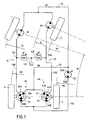
- FIG. 1 shows the position of the four driving wheels, 1, 2, 3 and 4 of a machine in a bend whose radius of curvature is R.
- the two front wheels, 1 and 2 are steered .
- the driver actuates the direction of the machine so as to rotate the wheels 1 and 2. These are therefore inclined so as to be placed on curves whose radii of curvature are respectively R 1 and R 2 .
- Rear wheels 3 and 4 are non-steered. In the turn, they are on curves whose radii of curvature are respectively R 3 and R 4 . It is thus possible to draw the directional outline of the machine, that is to say the curves defined by the evolution of the radii of curvature R 1 to R 4 as a function of the radius R or, rather, depending on the angle a which represents the inclination of the steering wheel which is external to the turn. Each of the wheels of the machine then has a greater or lesser distance to cover depending on whether the radius of curvature of the curve on which it is located is greater or smaller.
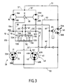
- the transmission circuit is a closed circuit and comprises a pump 50 with two orifices, respectively 50A and 50B, and variable rate.
- Motors 30 and 40 are dual engines, with two displacement cylinders, which correspond respectively to a first elementary motor, 31 to the engine 30 and 41 for the engine 40 and a second engine elementary, respectively 32 and 42.
- the motors 30 and 40 are so-called three-port motors. Indeed, the first elementary motors 31 and 41 comprise a first orifice 31A and 41A respectively, which serves, for example, in fluid, while the second elementary motors comprise a second port, respectively 32A and 42A, which is also used by example to the fluid supply.
- the third port, respectively 30B and 40B is common to, respectively, the elementary motors 31 and 32 and the elementary motors 41 and 42. This third port serves example to the escape of fluid.
- the motors 10 and 20 present each two orifices, respectively 10A and 20A, for example for feeding in fluid and 10B and 20B, for example for the escape of fluid.
- Engines may have a preferred direction of operation to ensure forward movement of the vehicle, but they are usually reversible, for reversing.
- the first elementary motors 31 and 41 of the 30 and 40 engines are connected to the pump 50 in parallel with the motors 10 and 20. Indeed, the first port 50A of the pump is connected to the orifices 10A and 20A motors 10 and 20 by a pipe 51 and its end branches 51 ', while the first orifices 31A and 41A of the elementary motors 31 and 41 are connected to the same port 50A of the pump by a pipe 52 and its terminal branches 52 '.
- the second elementary motors 32 and 42 are connected in series with, respectively, the motors 10 and 20.
- the orifice 32A of the elementary motor 32 is connected to the second port 10B of the motor 10 by a first line of series 12
- the orifice 42A of the elementary motor 42 is connected to the second port 20B of the motor 20 by a second line of series 22.
- the return to the pump 50 is through the orifices 30B and 40B of the motors 30 and 40 which are connected to the orifice 50B of the pump by a 53.
- the preferred direction of operation of the pump is such that the engines 10 and 20 are powered before the engines 30 and 40.
- the pipes 51 and 52 are then pipes of repression of the pump and motor supply, while the pipe 53 is the pipe back to the pump.
- the 12 series and 22 are exhaust pipes for motors 10 and 20 and supply lines for elementary motors 32 and 42.
- the circuit further comprises a booster pump 60 which, by a booster line 61 on which are placed check valves 62, prevents cavitation in hydraulic components now a minimum pressure called gavage pressure in the different pipes mentioned above.
- the transmission device comprises a valve 70 which has three connections.
- first connection 70A it is connected to the first line of series 12; by his second connection 70B, it is connected to the second line of series 22; and by its third connection 70C, it is connected to the pipe 53 and, by therefore, at the port 50B of the pump.
- the third connection 70C is connected to that of the two ports of the pump which is not connected to the motors 10 and 20 of the second group of engines.
- the pipe 12 consists of a first section 12A connected to the port 10B of the engine 10 and a second section 12B connected to the orifice 32A. These two sections join in a node N12 and are so bypass on a 12C pipe section that is connected to the 70A connection of the valve 70.
- the pipe 22 consists of a first and second sections 22A and 22B respectively connected to ports 20B and 42A and joining at node N22, where they are in branch on a pipe section 22C which is connected to the 70B connection.
- the sections 12A, 12B, 12C, 22A, 22B and 22C are also identified in Figure 1.
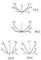
- FIG. 2 shows the variations of q 1 and q 2 as a function of the angle ⁇ which represents the inclination of the steering wheel which is outside the bend. It can be seen that q 1 / Q 1 is less than q 2 / Q 1 when the angle a is positive (right-turning) while q 1 / Q 1 is greater than q 2 / Q 1 when the angle a is negative. (left turn). Thanks to the selection valve of the invention, by calibrating the passage sections of the right and left branches of said valve, it is ensured that the pressures in the series ducts are substantially the same. For example, in a right turn, the right branch of the valve connected to the series line 12 has a passage section for the flow q 1 which is smaller than the passage section of the right branch of the valve connected to the series 22 pipe for the flow q 2 .
- the selection valve 70 can adopt three configurations.
- the connections 70A, 70B and 70C are isolated from each other. This is a configuration in which the vehicle moves in a straight line, all the wheels being animated the same speed.
- the second configuration of the valve is that of a left turn in which the first connection 70A is connected to the connection 70C by a first left branch 71A, while that the connections 70B and 70C are connected by a second branch left 71B.
- the third configuration of the valve is that of a turn to right, in which the connections 70A and 70C are connected by a first straight branch 72A, while the connections 70B and 70C are connected by a second straight branch 72B.
- Figure 3 is symbolized by restrictions placed on branches 71A and 72B the fact that the passage sections in at least some of the right and left branches are different.
- the flow q 1 and q 2 are different, so that, for example in a left turn, the flow rates in the first and second left branches 71A and 71B are different.
- the passage sections in these branches can be calculated so that, taking into account this difference in flow rate, the pressures in the two branches are substantially the same.
- the branch 71B is that which is connected to the motors 20 and 40 outer wheels in left turn
- the branch 72A is the one that is connected to the outboard motors 10 and 30 in corner to right.
- branches 71A and 72B show that we have chosen to make the passage section more big in the branch connected to the motors that drive the wheels outside the turn than in the other branch.
- the tensile force that can be provided by the outside steering wheel is more important than the one that can provide the inner steering wheel.
- the forward direction shown in Figure 3 is the one that is preferential for four-wheel drive vehicles, including two-wheelers before are guidelines, for example agricultural machinery such as four-wheel grape harvesters. However, there are four drive wheels whose rear wheels are steered. In this case, the preferential direction of feeding forward will be rather the meaning opposite of that shown in Figure 3. In this case also, if they are the front wheels which are driven by the twin engines 30 and 40, one may instead choose to reduce the section of branches 71B and 72A compared to that of the branches 71A and 72B, to obtain the same result, namely a greater traction force in the front wheel outside the bend.
- the motors 10 and 20 of the two wheels are single-displacement engines.
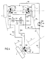
- FIG. 4 shows the position of the three driving wheels 1 ', 2' and 3 'of a machine in a turn whose radius of curvature is R'.
- the isolated rear wheel 3 ' is director.
- the three wheels 1 ', 2' and 3 'of the vehicle move on curves whose radii of curvature are respectively R 1 , R 2 and R 3 .
- FIG. 6 shows more precisely the device of the invention applied to the transmission circuit of the three-wheeled vehicle of Figure 4.
- This circuit comprises a pump 150 which, via a pipe 151 connected to its orifice 150A, feeds a motor 110 which drives the wheel isolated, which is the rear and steering wheel.
- a pump 150 which, via a pipe 151 connected to its orifice 150A, feeds a motor 110 which drives the wheel isolated, which is the rear and steering wheel.
- the meaning preferential circulation of fluid is that in which the engine that drives the isolated steering wheel is powered first.
- the engine 110 is a twin engine, which includes two engine distinct functioning which correspond respectively to a first elementary motor 111 and a second elementary motor 113.
- This is a three-port motor, similar to the 30 and 40 engines of FIG. 3.
- the orifice 110A which, in the forward direction, is an orifice power supply, is common to the elementary motors 111 and 113, while that fluid escape outside these two elementary motors is made through holes 111B and 113B which are specific to them.
- the two non-steered front wheels of the vehicle of Figure 6 are Driven by two twin engines, 130 and 140, similar to the engines 30 and 40 of FIG. 3.
- the elementary motors 131 and 132 with their feed ports in forward 131A and 132A and their common exhaust port 130B, as well as recognizing the elementary motors 141 and 142, with their feed orifices forward 141A and 142A and their common exhaust port 140B.
- the first elementary motors 131 and 141 are connected to the orifice 150A of the pump via the pipe 152, in branch on the
- the second elementary motors 132 and 142 are connected to, respectively, the orifice 111B of the first elementary motor 111 of the engine 110 and the orifice 113B of the second elementary motor 113 of this double motor, by two series ducts, respectively 112 and 122.
- a force-feeding pressure is maintained in using a booster pump 160.
- the circuit of FIG. 6 comprises a selection valve 170, whose the different connections and branches are affected by the same references than those of the valve 70, increased by 100.
- the connection 170C is connected to the second port 150B of the pump 150 by the return line 153, to which the orifices are also connected 130B and 140B engines 130 and 140. It has also been schematized restrictions placed on the left second branch 171B and on the first right branch 172A.
- Conduct 112 consists of a first and a second 112A and 112B, respectively connected to the orifice 111B of the engine 110 and 132A. These two sections meet in a knot N112 and are therefore bypass on a pipe section 112C which is connected to the connection 170A of the valve 170.
- the conduit 122 is composed of first and second sections 122A and 122B, respectively connected to ports 113B and 142A and joining at the node N122, to which they are in derivation on a section of pipe 122C which is connected to the connection 170B.
- the sections 112A, 112B, 112C, 122A, 122B and 122C are also identified in Figure 4.
- Figure 5 shows the variations of q 1 and q 2 as a function of the angle ⁇ which represents the turning inclination of the isolated steering wheel. It can also be seen that q 1 / Q 1 is less than q 2 / Q 1 when the angle a is positive (right-turning) while q 1 / Q 1 is greater than q 2 / Q 1 when the angle a is negative (left turn).
- the selection valve according to the invention makes it possible to ensure that the pressures in the series ducts are substantially the same.
- the passage section in branch 171B (branch "outside" in a left turn) is less than the passage section in branch 171A.
- lines 112 and 122 serve to the power supply of the elementary motors 132 and 142.
- the pressure is more important in driving 112 than in the pipe 122, which means that the pressure difference between 130A power supply and 130B motor exhaust terminals elementary 132 is greater than the pressure difference across of the elementary engine 142.
- the situation is the opposite during a turn to left. Therefore, the tensile force that can provide the front wheel outside a turn is greater than that which can be provided by the front wheel interior.
- the insulated and steering wheel should be the front wheel. In this case, this wheel would also be powered by the front pump non-steering wheels. We will then choose to place the restrictions as in Figure 3.
- FIG. 3 schematically shows a system 80 for detecting the angular position of the steering wheels.
- this system controls the progressive displacement of the valve 70 between one or the other of its configurations.
- the system 180 of detecting the angular position of the steering wheel driven by the motor 110 of the circuit of FIG. 6 is connected by a command 182 to the progressive valve 170.
- the control means of the configuration of the selection valve 70 or 170 take into account the angular position steering displacement organs.
- the selection valve includes a drawer that can occupy three stable positions defining respectively the first, second and third configurations of this valve and the laws of variation of the passage sections in the right and left branches of this valve during the movement of the drawer between these different positions are determined according to the purity of direction of the craft.
- the section of passage in a branch determines the pressure drop on either side of this branch, that is to say for example the pressure difference between the pipe 53 and the series pipe that communicates with this branch.
- passage section in the other branch determines the pressure drop between the pipe 53 and the pipe 22. results that the relationships between the passage sections in both right branches or in the left two branches determine the pressure difference between the two series lines.
- the laws of variation of the passage sections in the various branches of the selection valve are such that said variations as a function of the angular position of the displacement members are proportional to the variations, also depending the angular position of the displacement members, fluid flow rates q 1 and q 2 which are necessary in the right and left branches of the valve to cause a displacement of the displacement members substantially without slipping thereof relative to the ground.
- this ratio of proportionality makes it possible to ensure that the pressure drops are substantially equal in each of the two right branches or in each of the two left branches, so that the fluid pressures in the two series lines, 12 and 22 or 112 and 122, are substantially equal.
- FIGS. 7A, 7B and 7C designate by reference 270 a valve in accordance with the invention, which may be the valves 70 or 170 of the FIG. 3 or 6.
- This valve comprises a drawer 280 that can occupy three positions, respectively shown in Figures 7A, 7B and 7C.
- This drawer is movable in a bore 282 formed in the body 284 of the valve.
- This body has three orifices 270A, 270B and 270C, which corresponding respectively to the connections 70A, 70B and 70C or connections 170A, 170B and 170C of the valves 70 or 170.
- These orifices are connected to annular grooves, respectively 282A, 282B and 282C, which are formed in the bore 282 by transverse holes.
- annular grooves respectively 280A, 280B and 280C, are provided on the outer cylindrical surface of the drawer.
- the throat 280C is located between the grooves 280A and 280B, as well as the groove 282C is located between grooves 282A and 282B.
- Figure 7A shows the straight line configuration of valve 270 and it can be seen that the grooves 282A, 282B and 282C are isolated from each other other intermediate portions 281A and 281B of the drawer, located between the grooves 280A and 280C on the one hand and between the grooves 280C and 280B on the other hand.
- the drawer is held in this intermediate position by the effort antagonist of two springs, respectively 290 and 292, located at each of its ends.
- the notches 283A of the intermediate portion 281A define the fluid passage section between the connections 270C and 270A
- the notches 283B of the intermediate portion 281B define the passage section between the connections 270C and 270B.
- the notches 283B are deeper than the notches 283A, so that, the pressure difference between the connection 270C and the connection 270B is less important than the pressure difference between the 270C and 270A connection.
- this position in which the drawer is moved to the left corresponds to the turn configuration to left of the valve 70 of FIG.
- valve drawer is moved left turn left and right turn right.
- direction of movement depends on the control means used and the restrictions in the different branches of this valve are arranged accordingly.
- the valve 270 is controlled by means of two electromagnets, respectively at each of its ends, whose electrical controls, respectively 294 and 296. These commands are connected to power supply lines of known manner in itself. These lines are powered according to the angular position of the steering units of the machine on the transmission circuit of which is mounted this valve. In addition, these power lines may include on / off switches, which make it possible to order the putting into service and out of service of electromagnets (not shown).
- power controllers are arranged on the power lines, to vary the power supply of the electromagnets of progressive way. This allows, when the electromagnets are put in service, move the valve drawer more or less to either of its positions according to the value of the inclination of the organs directors.
- Such a valve, controlled by electromagnets, is particularly suitable for the transmission circuit of a vehicle of the type forklift with three wheels.
- FIG. 8 shows a selection valve 370 according to another variant.
- elements similar to those of FIGS. 7A to 7C are assigned the same references, increased by 100.
- the configuration of bore 382 and drawer 380 are the same as those of the bore 282 and the drawer 280 of FIGS. 7A to 7C.
- a control chamber 400 is provided at a end of the drawer, this chamber being connected to a source of fluid by a conduit 402, for example a secondary conduit connected to the booster pump for feeding the chamber and to a tank of fluid for its emptying.
- a spring 390 whose effect is antagonistic to that of the pressure of the contained fluid in room 400.
- This valve 370 is controlled mechanically.
- a control rod 404 capable of being displaced in translation by a cam system 405.
- FIG. 8 shows the situation in which the control rod 404 is moved as far as the right, so that the spring 390 pushes the drawer 380 in its extreme position to the right.
- the cam 406 cooperates with a rolling track 408.
- the rotation of the cam is controlled by control means 409, advantageously solicited by function of the angular position of the steering wheels of the vehicle.
- Cam 406 is shown schematically. We will understand however, his profile includes three distinct parts, respectively likely to control the selection valve in its configuration of straight line, in its left turn configuration and in its right turn configuration. Indeed, according to the part of the profile that cooperates with the track 408, the rod 404 is moved more or less to the left.
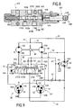
- FIG. 9 shows a circuit similar to that of FIG. 3, but wherein a valve 470 replaces the valve 70.
- the valve 470 comprises branches 473A and 473B which make it possible to connect the connections 470A, 470B and 470C without restriction, in a fourth configuration of the valve called "power configuration parallel".
- the four-position valve 470 can be analogous to the valve 370 of FIG. 8, the drawer 380 of which can be controlled in parallel supply position by fluid supply to the chamber 400 against return means such as the spring 390.
- the drawer 380 when we feed the chamber 400 by the duct 402 connected on feeding, the drawer 380 is moved so as to compress the spring 390 to come to a stop beyond the extreme position given by the 406.
- the connections 370A, 370B and 370C then communicate with each other. freely between them by the areas 373A and 373B of the drawer 380 of lesser diameter, these zones being an example of embodiment of the branches 473A and 473B of the valve 470.
- the chamber 400 and the spring 390 form means of parallel power control that are enabled by the power supply of the room 400. When this room is emptied, they are disabled and the drawer 380 can be ordered again between its three others positions.
- the motors 10 and 20 are connected to the pump 50 according to a full parallel connection with the first elementary motors 31 and 41, the orifices 10B and 20B being unrestrictedly connected to the orifice 50B in parallel with the orifices 30B and 40B.
- Branches 473A and 473B having no restrictions, the second elementary motors 32 and 42 are short-circuited and the wheels are out of sync.
- Additional valves may also be provided for bypass the first half-motors 31 and 41, thus limiting the displacement pump-powered, so as to increase the speed of the craft.
- Figures 10 and 11 show the evolution of passage sections in the left and right branches of the valve depending on the angle ⁇ mentioned above with reference to FIGS. 1 and 2 or FIGS. 5.
- the angle ⁇ is positive in a right turn.
- ⁇ 1 and ⁇ 2 respectively represent the evolution of the passage section of the first right branch 72A or 172A of the valve and that of the second right branch 72B or 172B of the valve during the progressive changeover. from this valve from its straight line configuration to its right turn configuration.
- ⁇ 1 and ⁇ 2 respectively represent the evolution of the passage section in the first left branch 71A or 171A and in the second left branch 71B or 171B during the gradual transition of the valve from its straight line position to its left turn position.
- this situation is obtained thanks to the fact that the linear functions are such that the slope of ⁇ 1 is lower than that of ⁇ 2 when ⁇ is positive and conversely when ⁇ is negative.
- this situation is obtained by appropriately choosing the threshold values of the angle ⁇ from which ⁇ 1 and ⁇ 2 take non-zero values.
- the selection valve of the invention is defined so as to ensure a given pressure deviation, zero deviations if it is desired to obtain equal pressures in the series or non-zero ducts of determined amplitude if the it is desired to obtain, between such or such wheels of the vehicle, a transfer of the tensile forces in given proportions.
Landscapes
- Engineering & Computer Science (AREA)
- Mechanical Engineering (AREA)
- Chemical & Material Sciences (AREA)
- Combustion & Propulsion (AREA)
- Transportation (AREA)
- General Engineering & Computer Science (AREA)
- Arrangement And Driving Of Transmission Devices (AREA)
Description
- la figure 1 illustre schématiquement le comportement en virage d'un engin à quatre roues motrices, entraínées par des moteurs hydrauliques ;
- la figure 2 montre les variations des débits de fluide dans les conduites de série du circuit de transmission de l'engin de la figure 1 en fonction de l'inclinaison de la roue directrice qui est extérieure au virage ;
- la figure 3 représente un circuit illustrant le dispositif de l'invention, pour un engin à quatre roues motrices du type représenté sur la figure 1 ;
- la figure 4 est une vue analogue à la figure 1, pour un engin à trois roues ;
- la figure 5 est une vue analogue à la figure 2, pour le circuit de transmission de l'engin de la figure 4 ;
- la figure 6 représente un circuit illustrant le dispositif de l'invention appliqué à un engin à trois roues motrices ;
- les figures 7A, 7B et 7C montrent une valve de sélection en coupe longitudinale, dans chacune de ses trois configurations ;
- la figure 8 est une vue analogue à la figure 7A, montrant une variante de valve de sélection ;
- la figure 9 montre une variante du circuit de la figure 3 ; et
- les figures 10 et 11 montrent les variations des sections de passage dans les branches droites et gauches de la valve en fonction de l'inclinaison de la roue directrice extérieure de l'engin de la figure 1 ou de la roue directrice unique de l'engin de la figure 4.
Claims (15)
- Dispositif de transmission hydrostatique d'un engin mobile ayant un groupe d'organes de déplacement avant (1, 2 ; 1', 2') et un groupe d'organes de déplacement arrière (3, 4 ; 3'), le ou les organes de déplacement (1, 2 ; 3') d'un desdits groupes étant directeurs, le dispositif comprenant un circuit de transmission qui comporte une pompe (50 ; 150) et des moteurs hydrauliques d'un groupe de moteurs avant (10, 20 ; 130, 140) et d'un groupe de moteurs arrière (30, 40 ; 110), pour les organes de déplacement des groupes avant et arrière, un premier des groupes de moteurs avant et arrière comprenant au moins deux moteurs (30, 40 ; 130, 140) auxquels sont respectivement attelés deux organes de déplacement (3, 4 ; 1', 2') situés de chaque côté de l'engin, tandis que le deuxième groupe de moteurs comprend au moins un moteur (10, 20 ; 110) auquel est attelé au moins un organe de déplacement (1, 2 ; 3'), les deux moteurs (30, 40 ; 130, 140) du premier groupe de moteurs étant des moteurs doubles, à deux cylindrées distinctes de fonctionnement qui correspondent respectivement à un premier (31, 41; 131, 141) et à un deuxième (32, 42; 132, 142) moteur élémentaire, le premier moteur élémentaire (31, 41; 131, 141) de chacun de ces moteurs doubles (30, 40; 130, 140) étant relié à la pompe (50; 150) en parallèle (51, 52; 151, 152) avec un moteur (10, 20 ; 110) du deuxième groupe de moteurs, tandis que le deuxième moteur élémentaire (32, 42; 132, 142) est relié en série avec ledit moteur (10, 20 ; 120) du deuxième groupe, une première et une deuxième conduite (12, 22 ; 112, 122) de série existant ainsi entre les deuxièmes moteurs élémentaires de chacun des deux moteurs doubles et le deuxième groupe de moteurs,
caractérisé en ce qu'il comprend une valve de sélection (70 ; 170 ; 270 ; 370; 470) reliée à la première conduite de série (12 ; 112) par une première connexion (70A ; 170A ; 270A ; 370A; 470A), a la deuxième conduite de série (22 ; 122) par une deuxième connexion (70B ; 170B ; 270B ; 370B; 470B) et à un orifice (50B ; 150B) de la pompe (50 ; 150) par une troisième connexion (70C ; 170C ; 270C ; 370C; 470C), en ce que ladite valve est susceptible d'occuper une configuration dite de ligne droite dans laquelle les trois connexions précitées sont isolées les unes des autres, une configuration dite de virage à gauche, dans laquelle les première et troisième connexions sont reliées par une communication dite première branche gauche (71A ; 171A; 471A) tandis que les deuxième et troisième connexions sont reliées par une communication dite deuxième branche gauche (71B; 171B); 471B et une configuration dite de virage à droite, dans laquelle les première et troisième connexions sont reliées par une communication dite première branche droite (72A ; 172A; 472A) tandis que les deuxième et troisième connexions sont reliées par une communication dite deuxième branche droite (72B ; 172B;472B) et en ce que les sections de passage de certaines, au moins, desdites branches droites et gauches sont différentes. - Dispositif selon la revendication 1, caractérisé en ce que la deuxième branche droite (72B ; 172B; 472B) et la première branche gauche (71A ; 171A ;471A) ont sensiblement la même section de passage maximale qui est supérieure aux sections de passage maximales de la première branche droite (72A; 172A; 472A) et de la deuxième branche gauche (71B ; 171B; 471B).
- Dispositif selon la revendication 1 ou 2, caractérisé en ce qu'il comporte des moyens de commande (82 ; 182; 294, 296; 409) de la configuration de la valve de sélection (70 ; 170; 270; 370; 470) qui prennent en compte (80 ; 180) la position angulaire des organes de déplacement directeurs.
- Dispositif selon l'une quelconque des revendications 1 à 3, caractérisé en ce que la valve de sélection (70; 170; 270 ; 370; 470) est une valve progressive.
- Dispositif selon la revendication 4, caractérisé en ce que la valve de sélection (70 ; 170 ; 270; 370; 470) comprend un tiroir (280 ; 380) susceptible d'occuper trois positions stables définissant respectivement les première, deuxième et troisième configurations de ladite valve et en ce que les lois de variation des sections de passage dans les branches droites et gauches de la valve de sélection au cours du déplacement de ce tiroir entre ses différentes positions sont déterminées en fonction de l'épure de direction de l'engin.
- Dispositif selon les revendications 3, 4 et 5, caractérisé en ce que lesdites variations des sections de passage en fonction de la position angulaire (80 ; 180) des organes de déplacement directeurs sont proportionnelles aux variations, en fonction de la position angulaire des organes de déplacement directeurs, des débits de fluides (q1, q2) qui sont nécessaires dans les branches droites et gauches (71A, 71B, 72A, 72B ; 171A, 171B, 172A, 172B; 471A, 471B, 472A, 472B) de la valve de sélection (70; 170; 270; 370; 470) pour provoquer un déplacement des organes de déplacement sensiblement sans patinage de ces derniers par rapport au sol.
- Dispositif selon l'une quelconque des revendications 1 à 6, caractérisé en ce que chacun des deux groupes d'organes de déplacement (1, 2, 3, 4) comprend deux organes de déplacement situés de chaque côté de l'engin, le deuxième groupe de moteurs comprenant un premier et un deuxième moteur (10, 20) auxquels sont respectivement attelés deux organes de déplacement (1, 2) qui sont les organes de déplacement directeurs et en ce que la première conduite de série (12) relie le deuxième moteur élémentaire (32) de l'un (30) des moteurs du premier groupe de moteurs au premier moteur (10) du deuxième groupe, tandis que la deuxième conduite de série (22) relie le deuxième moteur élémentaire (42) de l'autre moteur (40) du premier groupe de moteurs au deuxième moteur (20) du deuxième groupe.
- Dispositif selon l'une quelconque des revendications 1 à 7, dans lequel, en marche avant de l'engin, les conduites de série (12, 22) sont des conduites d'alimentation en fluide des deuxièmes moteurs élémentaires (32, 42) des moteurs doubles (30, 40) du premier groupe de moteurs, lesdits moteurs doubles entraínant des organes de déplacement arrière, caractérisé en ce que les sections de passage dans les branches droites (72A, 72B; 472A, 472B) et gauches (71A, 71B; 471A, 471B) de la valve de sélection (70 ; 270 ; 370; 470) sont déterminées de telle sorte que, dans un virage à droite ou à gauche, la section de passage dans la branche droite ou gauche (72A, 71B; 472A, 471B) à laquelle est reliée la conduite de série (12, 22) raccordée au deuxième moteur élémentaire (32, 42) de celui des moteurs (30, 40) du premier groupe qui entraíne l'organe de déplacement extérieur au virage est supérieure à la section de passage dans l'autre branche droite ou gauche (72B, 71A; 472B, 471A).
- Dispositif selon l'une quelconque des revendications 1 à 6, caractérisé en ce que le deuxième groupe de moteurs comporte un moteur double (110) à deux cylindrées distinctes de fonctionnement qui correspondent respectivement à un premier et à un deuxième moteur élémentaire (111, 113), un unique organe de déplacement (3'), qui est directeur, étant attelé à ce moteur double et en ce que la première conduite de série (112) relie le deuxième moteur élémentaire (132) de l'un (130) des moteurs du premier groupe de moteurs au premier moteur élémentaire (111) du moteur double (110) du deuxième groupe, tandis que la deuxième conduite de série (122) relie le deuxième moteur élémentaire (142) de l'autre moteur (140) du premier groupe de moteurs au deuxième moteur élémentaire (113) dudit moteur double (110) du deuxième groupe.
- Dispositif selon l'une quelconque des revendications 1 à 7 ou la revendication 9, dans lequel, en marche avant de l'engin, les conduites de série (112, 122) sont des conduites d'alimentation en fluide des deuxièmes moteurs élémentaires (132, 142) des moteurs doubles (130, 140) du premier groupe de moteurs, lesdits moteurs doubles entraínant les organes de déplacement avant (1', 2'), caractérisé en ce que les sections de passage dans les branches droites (172A, 172B) et gauches (171A, 171B) de la valve de sélection (170 ; 270; 370) sont déterminées de telle sorte que, dans un virage à droite ou à gauche, la section de passage dans la branche droite (172A, 171B) ou gauche à laquelle est reliée la conduite de série (112, 122) raccordée au deuxième moteur élémentaire de celui des moteurs (130, 140) du premier groupe qui entraíne l'organe de déplacement extérieur au virage est inférieure à la section de passage dans l'autre branche droite ou gauche (1728, 171A).
- Dispositif selon l'une quelconque des revendications 1 à 10, caractérisé en ce que les moyens de commande de la valve de sélection (270) comprennent deux électroaimants (294, 296) susceptibles d'être alimentés en fonction de la direction (80, 180) des organes de déplacement directeurs pour commander respectivement le passage de ladite valve (270) de sa configuration de ligne droite à sa configuration de virage à gauche et à sa configuration de virage à droite et en ce qu'il comporte des moyens pour commander la mise en service et hors service de ces électroaimants.
- Dispositif selon la revendication 11, caractérisé en ce qu'il comporte des moyens pour faire varier l'alimentation des électroaimants de manière progressive.
- Dispositif selon l'une quelconque des revendications 1 à 10, caractérisé en ce que les moyens de commande de la valve de sélection (370) comprennent un système de came (405, 406) dont le profil comprend trois parties distinctes, respectivement susceptibles de commander la valve de sélection dans sa configuration de ligne droite, dans sa configuration de virage à gauche et dans sa configuration de virage à droite.
- Dispositif selon l'une quelconque des revendications 1 à 13, caractérisé en ce que la valve de sélection (370 ; 470) est susceptible d'adopter, en outre, une configuration d'alimentation parallèle dans laquelle les première, deuxième et troisième connexions (370A, 370B, 370C ; 470A, 470B, 470C) sont reliées entre elles sans restriction (373A, 373B ; 473A, 473B) et en ce qu'il comporte des moyens de commande d'alimentation parallèle susceptibles d'être activés pour commander le passage de la valve de sélection (370 ; 470) dans sa configuration d'alimentation parallèle et d'être désactivés pour autoriser le passage de la valve de sélection dans une autre de ses configurations.
- Dispositif selon la revendication 14, caractérisé en ce que la valve de sélection (370, 470) comprend un tiroir de sélection (380) et en ce que les moyens de commande d'alimentation parallèle comprennent une chambre de pilotage hydraulique (400) susceptible d'être alimentée en fluide sous pression pour déplacer le tiroir de sélection (380) vers une position définissant la configuration d'alimentation parallèle, à l'encontre de moyens de rappel (390) de ce tiroir de sélection.
Applications Claiming Priority (2)
| Application Number | Priority Date | Filing Date | Title |
|---|---|---|---|
| FR9815873 | 1998-12-16 | ||
| FR9815873A FR2787396B1 (fr) | 1998-12-16 | 1998-12-16 | Dispositif de transmission pour un engin mobile a valve de commande du comportement en virage |
Publications (2)
| Publication Number | Publication Date |
|---|---|
| EP1010566A1 EP1010566A1 (fr) | 2000-06-21 |
| EP1010566B1 true EP1010566B1 (fr) | 2003-04-16 |
Family
ID=9534030
Family Applications (1)
| Application Number | Title | Priority Date | Filing Date |
|---|---|---|---|
| EP99403145A Expired - Lifetime EP1010566B1 (fr) | 1998-12-16 | 1999-12-15 | Dispositif de transmission pour un engin mobile à valve de commande du comportement en virage |
Country Status (4)
| Country | Link |
|---|---|
| US (1) | US6354392B1 (fr) |
| EP (1) | EP1010566B1 (fr) |
| DE (1) | DE69906920T2 (fr) |
| FR (1) | FR2787396B1 (fr) |
Cited By (1)
| Publication number | Priority date | Publication date | Assignee | Title |
|---|---|---|---|---|
| US8627657B2 (en) | 2006-10-18 | 2014-01-14 | Poclain Hydraulics Industrie | Vehicle hydrostatic transmission device |
Families Citing this family (20)
| Publication number | Priority date | Publication date | Assignee | Title |
|---|---|---|---|---|
| DE10025508B4 (de) * | 2000-05-23 | 2009-02-05 | Sauer-Danfoss Holding Aps | Fahrzeug-Antriebsanordnung |
| FR2828544B1 (fr) * | 2001-08-09 | 2003-12-12 | Poclain Hydraulics Ind | Dispositif de transmission hydrostatique d'un engin mobile |
| US7100732B2 (en) * | 2002-09-04 | 2006-09-05 | Parker-Hannifin Corporation | Positive traction hydraulic drive system |
| US7044259B2 (en) * | 2003-04-10 | 2006-05-16 | Kerwyn Stoll | Hydraulic transmission for driving and steering wheels |
| FR2861448B1 (fr) | 2003-10-28 | 2006-02-10 | Poclain Hydraulics Ind | Dispositif de transmission hydrostatique d'un engin mobile avec echange |
| US7017703B2 (en) * | 2004-06-22 | 2006-03-28 | Sauer-Danfoss Inc. | Four wheel traction control valve |
| US7377353B2 (en) * | 2004-07-29 | 2008-05-27 | Sauer-Danfoss Inc. | Four wheel traction control valve system |
| FI119274B (fi) * | 2005-12-02 | 2008-09-30 | John Deere Forestry Oy | Ohjauskytkentä karsinta- ja katkaisulaitteiston syöttöelimien syöttönopeuden muuttamiseksi |
| US20070169980A1 (en) * | 2006-01-23 | 2007-07-26 | Cnh America Llc | Transmissionless agricultural vehicle drive system |
| FR2953897B1 (fr) * | 2009-12-14 | 2012-01-20 | Poclain Hydraulics Ind | Gavage supplementaire pour circuit de transmission hydrostatique |
| JP5581479B2 (ja) * | 2010-07-05 | 2014-09-03 | 株式会社 神崎高級工機製作所 | 油圧四輪駆動作業車輌 |
| FR2978995B1 (fr) * | 2011-08-08 | 2015-07-24 | Poclain Hydraulics Ind | Dispositif de transmission hydrostatique assurant une bonne motricite |
| DE102011118255A1 (de) * | 2011-11-11 | 2013-05-16 | Robert Bosch Gmbh | Hydrostatischer Fahrantrieb und Fahrzeug mit einem derartigen Fahrantrieb |
| AU2013202966B2 (en) * | 2012-01-25 | 2015-11-26 | Crown Equipment Corporation | System and method for monitoring state of function of a materials handling vehicle |
| KR102155274B1 (ko) * | 2020-06-22 | 2020-09-11 | (주)유원산업 | 허리굴절식 스키드 로더 |
| KR102155282B1 (ko) * | 2020-06-22 | 2020-09-11 | (주)유원산업 | 허리굴절식 스키드 로더 |
| KR102155293B1 (ko) * | 2020-06-22 | 2020-09-11 | (주)유원산업 | 허리굴절식 스키드 로더 |
| KR102155287B1 (ko) * | 2020-06-22 | 2020-09-11 | (주)유원산업 | 허리굴절식 스키드 로더 |
| KR102155301B1 (ko) * | 2020-06-22 | 2020-09-11 | (주)유원산업 | 허리굴절식 스키드 로더 |
| KR102155279B1 (ko) * | 2020-06-22 | 2020-09-11 | (주)유원산업 | 허리굴절식 스키드 로더 |
Family Cites Families (5)
| Publication number | Priority date | Publication date | Assignee | Title |
|---|---|---|---|---|
| FR2685263B1 (fr) | 1991-12-19 | 1994-03-25 | Poclain Hydraulics | Engin mobile comportant des moteurs hydrauliques avant et arriere d'entrainement. |
| FR2719001B1 (fr) | 1994-04-20 | 1996-07-26 | Ecb Sarl | Dispositif de transmission hydraulique pour un engin tracteur agricole comportant une roue avant directrice et motrice et au moins deux roues arrière motrices. |
| US5682958A (en) * | 1995-09-18 | 1997-11-04 | Deere & Company | Rear wheel assist for a self-propelled scraper |
| EP0816153B1 (fr) | 1996-06-28 | 2003-03-05 | Moffett Research and Development Limited | Système d'entraínement hydraulique |
| FR2789351B1 (fr) * | 1999-02-05 | 2001-04-27 | Poclain Hydraulics Ind | Dispositif de transmission d'un engin mobile ayant au moins deux ponts moteurs |
-
1998
- 1998-12-16 FR FR9815873A patent/FR2787396B1/fr not_active Expired - Fee Related
-
1999
- 1999-12-15 EP EP99403145A patent/EP1010566B1/fr not_active Expired - Lifetime
- 1999-12-15 US US09/461,318 patent/US6354392B1/en not_active Expired - Lifetime
- 1999-12-15 DE DE69906920T patent/DE69906920T2/de not_active Expired - Lifetime
Cited By (1)
| Publication number | Priority date | Publication date | Assignee | Title |
|---|---|---|---|---|
| US8627657B2 (en) | 2006-10-18 | 2014-01-14 | Poclain Hydraulics Industrie | Vehicle hydrostatic transmission device |
Also Published As
| Publication number | Publication date |
|---|---|
| FR2787396B1 (fr) | 2001-03-09 |
| US6354392B1 (en) | 2002-03-12 |
| EP1010566A1 (fr) | 2000-06-21 |
| FR2787396A1 (fr) | 2000-06-23 |
| DE69906920T2 (de) | 2004-02-05 |
| DE69906920D1 (de) | 2003-05-22 |
Similar Documents
| Publication | Publication Date | Title |
|---|---|---|
| EP1010566A1 (fr) | Dispositif de transmission pour un engin mobile à valve de commande du comportement en virage | |
| EP1420973B1 (fr) | Dispositif de transmission hydrostatique d'un engin mobile. | |
| EP1026024B1 (fr) | Dispositif de transmission d'un engin mobile ayant au moins deux ponts moteurs | |
| US20030019682A1 (en) | ZTR with steerable wheels | |
| FR2722856A1 (fr) | Transmission pour vehicules de travail | |
| FR2495725A1 (fr) | Dispositif d'entrainement de deux arbres de transmission et commande d'un moteur a cylindree variable | |
| EP0072731B1 (fr) | Distributeur hydraulique à réaction sur organe de commande | |
| EP0547947A1 (fr) | Engin mobile comportant des moteurs hydrauliques avant et arrière d'entraînement | |
| US20010040057A1 (en) | Multi-wheel vehicle with transmission for driving-steering | |
| US5181579A (en) | Steering and driving system | |
| EP1026025B1 (fr) | Dispositif de transmission d'un engin mobile ayant au moins deux organes de déplacement moteurs en ligne | |
| WO2008116996A1 (fr) | Dispositif de transmission hydrostatique d'un engin mobile | |
| EP0424392B1 (fr) | Procede et dispositif de regulation du couple moteur transmis par un tracteur a une semi-remorque a entrainement hydraulique | |
| EP1058002B1 (fr) | Sélecteur de cylindrée pour un moteur hydraulique evitant un choc lors du changement de cylindrée | |
| FR2861448A1 (fr) | Dispositif de transmission hydrostatique d'un engin mobile avec echange | |
| FR2468815A1 (fr) | Valve de commande, notamment pour systemes de propulsion hydrostatiques de vehicules tels que tracteurs | |
| BE1007042A3 (fr) | Systeme de commande de direction a recuperation pour entrainements hydrostatiques. | |
| EP0025372A1 (fr) | Groupe propulseur à transmissions hydrostatiques assurant la translation et la direction avec recyclage hydraulique de puissance en virage | |
| FR2709454A1 (fr) | Transmission hydrostatique pour véhicules automoteurs et notamment pour machines agricoles. | |
| EP1387776B1 (fr) | Circuit de transmission hydrostatique d'engin | |
| FR2972146A1 (fr) | Dispositif de transmission hydrostatique d'un engin mobile, equipe d'une valve de controle de la pression. | |
| JP5176745B2 (ja) | トロイダル式無段変速機の油圧制御装置 | |
| FR3067984B1 (fr) | Vehicule automobile routier attelable | |
| EP0015169A1 (fr) | Circuit d'assistance motrice comprenant au moins un moteur à fluide | |
| FR2658131A3 (fr) | Vehicule propulse autoporte, notamment adapte pour tondre le gazon, muni d'un asservissement differentiel des roues motrices en fonction de l'angle de braquage des roues directrices. |
Legal Events
| Date | Code | Title | Description |
|---|---|---|---|
| PUAI | Public reference made under article 153(3) epc to a published international application that has entered the european phase |
Free format text: ORIGINAL CODE: 0009012 |
|
| AK | Designated contracting states |
Kind code of ref document: A1 Designated state(s): DE FR GB IE IT |
|
| AX | Request for extension of the european patent |
Free format text: AL;LT;LV;MK;RO;SI |
|
| 17P | Request for examination filed |
Effective date: 20001016 |
|
| AKX | Designation fees paid |
Free format text: DE FR GB IE IT |
|
| GRAG | Despatch of communication of intention to grant |
Free format text: ORIGINAL CODE: EPIDOS AGRA |
|
| 17Q | First examination report despatched |
Effective date: 20020430 |
|
| GRAG | Despatch of communication of intention to grant |
Free format text: ORIGINAL CODE: EPIDOS AGRA |
|
| GRAG | Despatch of communication of intention to grant |
Free format text: ORIGINAL CODE: EPIDOS AGRA |
|
| GRAH | Despatch of communication of intention to grant a patent |
Free format text: ORIGINAL CODE: EPIDOS IGRA |
|
| GRAH | Despatch of communication of intention to grant a patent |
Free format text: ORIGINAL CODE: EPIDOS IGRA |
|
| GRAA | (expected) grant |
Free format text: ORIGINAL CODE: 0009210 |
|
| AK | Designated contracting states |
Designated state(s): DE FR GB IE IT |
|
| REG | Reference to a national code |
Ref country code: GB Ref legal event code: FG4D Free format text: NOT ENGLISH |
|
| REF | Corresponds to: |
Ref document number: 69906920 Country of ref document: DE Date of ref document: 20030522 Kind code of ref document: P |
|
| REG | Reference to a national code |
Ref country code: IE Ref legal event code: FG4D Free format text: FRENCH |
|
| GBT | Gb: translation of ep patent filed (gb section 77(6)(a)/1977) | ||
| PLBE | No opposition filed within time limit |
Free format text: ORIGINAL CODE: 0009261 |
|
| STAA | Information on the status of an ep patent application or granted ep patent |
Free format text: STATUS: NO OPPOSITION FILED WITHIN TIME LIMIT |
|
| 26N | No opposition filed |
Effective date: 20040119 |
|
| PGFP | Annual fee paid to national office [announced via postgrant information from national office to epo] |
Ref country code: DE Payment date: 20121207 Year of fee payment: 14 |
|
| PGFP | Annual fee paid to national office [announced via postgrant information from national office to epo] |
Ref country code: IT Payment date: 20121217 Year of fee payment: 14 Ref country code: GB Payment date: 20121219 Year of fee payment: 14 |
|
| PGFP | Annual fee paid to national office [announced via postgrant information from national office to epo] |
Ref country code: IE Payment date: 20131122 Year of fee payment: 15 |
|
| REG | Reference to a national code |
Ref country code: DE Ref legal event code: R119 Ref document number: 69906920 Country of ref document: DE |
|
| GBPC | Gb: european patent ceased through non-payment of renewal fee |
Effective date: 20131215 |
|
| REG | Reference to a national code |
Ref country code: DE Ref legal event code: R119 Ref document number: 69906920 Country of ref document: DE Effective date: 20140701 |
|
| PG25 | Lapsed in a contracting state [announced via postgrant information from national office to epo] |
Ref country code: DE Free format text: LAPSE BECAUSE OF NON-PAYMENT OF DUE FEES Effective date: 20140701 |
|
| PG25 | Lapsed in a contracting state [announced via postgrant information from national office to epo] |
Ref country code: GB Free format text: LAPSE BECAUSE OF NON-PAYMENT OF DUE FEES Effective date: 20131215 |
|
| PG25 | Lapsed in a contracting state [announced via postgrant information from national office to epo] |
Ref country code: IT Free format text: LAPSE BECAUSE OF NON-PAYMENT OF DUE FEES Effective date: 20131231 |
|
| REG | Reference to a national code |
Ref country code: IE Ref legal event code: MM4A |
|
| PG25 | Lapsed in a contracting state [announced via postgrant information from national office to epo] |
Ref country code: IE Free format text: LAPSE BECAUSE OF NON-PAYMENT OF DUE FEES Effective date: 20141215 |
|
| REG | Reference to a national code |
Ref country code: FR Ref legal event code: PLFP Year of fee payment: 17 |
|
| PG25 | Lapsed in a contracting state [announced via postgrant information from national office to epo] |
Ref country code: IT Free format text: LAPSE BECAUSE OF NON-PAYMENT OF DUE FEES Effective date: 20131215 |
|
| REG | Reference to a national code |
Ref country code: FR Ref legal event code: PLFP Year of fee payment: 18 |
|
| REG | Reference to a national code |
Ref country code: FR Ref legal event code: PLFP Year of fee payment: 19 |
|
| PGFP | Annual fee paid to national office [announced via postgrant information from national office to epo] |
Ref country code: FR Payment date: 20171220 Year of fee payment: 19 |
|
| PG25 | Lapsed in a contracting state [announced via postgrant information from national office to epo] |
Ref country code: FR Free format text: LAPSE BECAUSE OF NON-PAYMENT OF DUE FEES Effective date: 20181231 |