EP1010499A1 - Articulated robot - Google Patents
Articulated robot Download PDFInfo
- Publication number
- EP1010499A1 EP1010499A1 EP99309082A EP99309082A EP1010499A1 EP 1010499 A1 EP1010499 A1 EP 1010499A1 EP 99309082 A EP99309082 A EP 99309082A EP 99309082 A EP99309082 A EP 99309082A EP 1010499 A1 EP1010499 A1 EP 1010499A1
- Authority
- EP
- European Patent Office
- Prior art keywords
- arm
- housing
- arm piece
- cover
- robot
- Prior art date
- Legal status (The legal status is an assumption and is not a legal conclusion. Google has not performed a legal analysis and makes no representation as to the accuracy of the status listed.)
- Granted
Links
Images

Classifications
-
- B—PERFORMING OPERATIONS; TRANSPORTING
- B25—HAND TOOLS; PORTABLE POWER-DRIVEN TOOLS; MANIPULATORS
- B25J—MANIPULATORS; CHAMBERS PROVIDED WITH MANIPULATION DEVICES
- B25J19/00—Accessories fitted to manipulators, e.g. for monitoring, for viewing; Safety devices combined with or specially adapted for use in connection with manipulators
- B25J19/0025—Means for supplying energy to the end effector
- B25J19/0029—Means for supplying energy to the end effector arranged within the different robot elements
-
- Y—GENERAL TAGGING OF NEW TECHNOLOGICAL DEVELOPMENTS; GENERAL TAGGING OF CROSS-SECTIONAL TECHNOLOGIES SPANNING OVER SEVERAL SECTIONS OF THE IPC; TECHNICAL SUBJECTS COVERED BY FORMER USPC CROSS-REFERENCE ART COLLECTIONS [XRACs] AND DIGESTS
- Y10—TECHNICAL SUBJECTS COVERED BY FORMER USPC
- Y10S—TECHNICAL SUBJECTS COVERED BY FORMER USPC CROSS-REFERENCE ART COLLECTIONS [XRACs] AND DIGESTS
- Y10S414/00—Material or article handling
- Y10S414/13—Handlers utilizing parallel links
-
- Y—GENERAL TAGGING OF NEW TECHNOLOGICAL DEVELOPMENTS; GENERAL TAGGING OF CROSS-SECTIONAL TECHNOLOGIES SPANNING OVER SEVERAL SECTIONS OF THE IPC; TECHNICAL SUBJECTS COVERED BY FORMER USPC CROSS-REFERENCE ART COLLECTIONS [XRACs] AND DIGESTS
- Y10—TECHNICAL SUBJECTS COVERED BY FORMER USPC
- Y10S—TECHNICAL SUBJECTS COVERED BY FORMER USPC CROSS-REFERENCE ART COLLECTIONS [XRACs] AND DIGESTS
- Y10S414/00—Material or article handling
- Y10S414/131—Transmission-line guide for a shiftable handler
-
- Y—GENERAL TAGGING OF NEW TECHNOLOGICAL DEVELOPMENTS; GENERAL TAGGING OF CROSS-SECTIONAL TECHNOLOGIES SPANNING OVER SEVERAL SECTIONS OF THE IPC; TECHNICAL SUBJECTS COVERED BY FORMER USPC CROSS-REFERENCE ART COLLECTIONS [XRACs] AND DIGESTS
- Y10—TECHNICAL SUBJECTS COVERED BY FORMER USPC
- Y10T—TECHNICAL SUBJECTS COVERED BY FORMER US CLASSIFICATION
- Y10T74/00—Machine element or mechanism
- Y10T74/20—Control lever and linkage systems
- Y10T74/20207—Multiple controlling elements for single controlled element
- Y10T74/20305—Robotic arm
- Y10T74/20311—Robotic arm including power cable or connector
-
- Y—GENERAL TAGGING OF NEW TECHNOLOGICAL DEVELOPMENTS; GENERAL TAGGING OF CROSS-SECTIONAL TECHNOLOGIES SPANNING OVER SEVERAL SECTIONS OF THE IPC; TECHNICAL SUBJECTS COVERED BY FORMER USPC CROSS-REFERENCE ART COLLECTIONS [XRACs] AND DIGESTS
- Y10—TECHNICAL SUBJECTS COVERED BY FORMER USPC
- Y10T—TECHNICAL SUBJECTS COVERED BY FORMER US CLASSIFICATION
- Y10T74/00—Machine element or mechanism
- Y10T74/20—Control lever and linkage systems
- Y10T74/20207—Multiple controlling elements for single controlled element
- Y10T74/20305—Robotic arm
- Y10T74/20317—Robotic arm including electric motor
-
- Y—GENERAL TAGGING OF NEW TECHNOLOGICAL DEVELOPMENTS; GENERAL TAGGING OF CROSS-SECTIONAL TECHNOLOGIES SPANNING OVER SEVERAL SECTIONS OF THE IPC; TECHNICAL SUBJECTS COVERED BY FORMER USPC CROSS-REFERENCE ART COLLECTIONS [XRACs] AND DIGESTS
- Y10—TECHNICAL SUBJECTS COVERED BY FORMER USPC
- Y10T—TECHNICAL SUBJECTS COVERED BY FORMER US CLASSIFICATION
- Y10T74/00—Machine element or mechanism
- Y10T74/20—Control lever and linkage systems
- Y10T74/20207—Multiple controlling elements for single controlled element
- Y10T74/20305—Robotic arm
- Y10T74/20329—Joint between elements
Definitions
- This invention relates to an articulated robot which has a robot arm of double arm structure composed of one arm piece formed as an endoskeletal arm to transmit a drive force and the other arm piece formed as an arm to house cables and/or pipes or the like.
- the robot may be, for example, an arc welding robot, a trimming robot, a handling robot or the like.
- a base 1 is mounted with a turn portion 2 which turns about the center of an axis perpendicular to a mounting surface (not shown) of the base 1.
- One end of a first arm piece 3a and that of a second arm piece 3b are fitted to the turn portion 2 so that these arm pieces 3a and 3b can rotate about the common axis perpendicular to the turning axis of the turn portion 2.
- the first arm piece 3a and the second arm piece 3b constitute a first robot arm 3 in double arm structure.
- the first arm piece 3a serving as one of the arms constituting the first robot arm 3, is of endoskeletal structure to transmit a drive force, and one end of the first arm piece 3a is rotatably fitted to the turn portion 2.
- the second arm piece 3b serving as the other of the arms constituting the first robot arm 3, is of structure to house cables and pipes or the like, and one end of the second arm piece is rotatably supported by the turn portion 2.
- a housing 4c is mounted to the other end of the first arm piece 3a and that of the second arm piece 3b so that the housing 4c can rotate about the common axis perpendicular to the center of turning axis of the turn portion 2.
- the housing 4c constitutes a second robot arm 4.
- a motor and a speed reducer (not shown) or the like for causing the second robot arm 4 to rotate relatively to the first robot arm 3, a motor and a speed reducer for causing a wrist 5, which will be later described, to rotate and air pipes and valves or the like for an end effector (not shown) are housed in the housing 4c.
- the housing 4c is open at its top, and a cover 4d for covering an open portion of the housing is mounted to the housing 4c with fixing means such as bolts. Further, the wrist 5 adapted to mount the end effector thereto is connected to the housing 4c (the second robot arm 4).
- the turn portion 2 makes a pivotal motion about the axis perpendicular to the mounting surface of the base 1, and the first robot arm 3, the second robot arm 4 and the wrist 5 are also turned together with the turn portion 2.
- a drive source (not shown) to drive the first robot arm 3 is operated to drive the first arm piece 3a
- the first arm piece 3a makes a pivotal motion relatively to the turn portion 2 to move the second robot arm 4.
- the second arm piece 3b is also rotatably moved whenever the first arm piece 3a is rotatably moved. The reason is that one end of the second arm piece 3b is rotatably supported by the turn portion 2, while the other end thereof is rotatably supported by the housing 4c (the second robot arm 4).
- the second robot arm 4 makes a pivotal motion relatively to the first robot arm 3 (the first arm piece 3a and the second arm piece 3b).
- An object of the present invention is to provide an articulated robot which facilitates the maintenance of equipment and parts in a housing and is easily assembled.
- an articulated robot comprising a first robot arm of double arm structure in which a first arm piece formed as an endoskeletal arm to transmit a drive force is installed parallel to a second arm piece to house a cable or pipe, and a second robot arm having one end rotatably supported by the end of the first robot arm.
- a housing of the second robot arm is rotatably supported by the end of the first arm piece
- a cover of the housing of the second robot arm is rotatably supported by the end of the second arm piece
- the cover is fixed to the housing through fixing means
- the housing is permitted to be opened by separating the housing and the cover from each other in the manner of causing the second arm piece to rotate relatively to the first arm piece after the removal of the fixing means.
- a base 1 is mounted with a turn portion 2 which turns about an axis perpendicular to a mounting surface (not shown) of the base 1.
- One end of a first arm piece 3a and that of a second arm piece 3b are fitted to the turn portion 2 so that the arm pieces 3a and 3b can rotate about the common axis perpendicular to the center of turning axis of the turn portion 2.
- the first arm piece 3a and the second arm piece 3b constitute a first robot arm 3 in double arm structure.
- the first arm piece 3a serving as one of the arms constituting the first robot arm 3, is of endoskeletal structure to transmit a drive force, and one end of the first arm piece 3a is rotatably fitted to the turn portion 2.
- the second arm piece 3b serving as the other of the arms constituting the first robot arm 3, is of structure to house cables and/or pipes or the like, and one end of the second arm piece is rotatably supported by the turn portion 2.
- a housing 4a is mounted to the first arm piece 3a at the other end thereof so that it can rotate about an axis perpendicular to the turning axis of the turn portion 2.
- the housing 4a constitutes a second robot arm 4.
- a motor M1 and a speed reducer or the like for causing the second robot arm 4 to rotate relatively to the first robot arm 3, a motor M2 and a speed reducer for causing a wrist 5 to rotate, and cables, air pipes and valves or the like for an end effector are housed within the housing 4a.
- the structure thereof is similar to that of the prior art.
- This embodiment is different from the prior art shown in Figs. 3 and 4 in that the open surface of the housing 4a of the second robot arm 4 according to this embodiment is formed to substantially face the second arm piece 3b. Then, a cover 4b for covering the open surface of the housing 4a is mounted to the housing 4a with a fixing tool or fixing means such as bolts.
- each of the housing 4a and the cover 4b has a shape like that resulting from longitudinally dividing a rectangular parallelepiped box into two parts along one of diagonal lines of a rectangular top surface of the rectangular parallelepiped box.
- the housing 4a and the cover 4b are combined together into a rectangular parallelepiped box.
- each of the housing and the cover is composed of upper and lower right-angled triangular plates, and two rectangular side plates each having sides equal in length to the sides making a right angle of each right-angled triangular plate.
- the housing and the cover takes the shape of a rectangular parallelepiped as a whole.
- the cover 4b is rotatably supported by the second arm piece 3b. As shown in Fig. 1, when the cover 4b is fixed to the housing 4a through the fixing tool 6, the turning axis of the housing 4a relative to the first arm piece 3a is in alignment with the turning axis of the cover 4b relative to the second arm piece 3b.
- the wrist 5 adapted to mount an end effector to its end is connected to the housing 4a (the second robot arm 4), similarly to the case in the prior art.
- the first and second robot arms 3, 4 and the wrist 5 are also turned together with the turn portion 2.
- a drive source (not shown) to drive the first robot arm 3 is operated to drive the first arm piece 3a
- the first arm piece 3a makes a pivotal motion relative to the turn portion 2 to move the second robot arm 4.
- the second arm piece 3b is driven by the first arm piece 3a through the housing 4a and the cover 4b and makes a pivotal motion together with the first arm piece 3a.
- the motor M1 to drive the second robot arm 4 is driven, the second robot arm 4 makes a pivotal motion relative to the first robot arm 3 (the first arm piece 3a and the second arm piece 3b).
- the maintenance of equipment such as the motors M1, M2 and speed reducers and parts such as pipes and cables in the housing 4a is carried out by separating the cover 4b from the housing 4a in the manner of causing the second arm piece 3b to rotate relatively to the first arm piece 3a in the direction opposite to the wrist as shown in Fig. 2 after the removal of the fixing tool 6 such as bolts. Since the second arm piece 3b is only rotatably supported by the turn portion 2, it is possible to freely rotate the second arm piece 3b as shown in Fig. 2.
- the cover 4b is separated from the housing 4a by the pivotal motion of the second arm piece 3b to open the housing 4a.
- each of the housing 4a and the cover 4b has a shape like that resulting from longitudinally dividing the rectangular parallelepiped box into two parts along one of diagonal lines of the rectangular top surface, as shown in Fig. 1.
- the rear surface i.e., the side opposite to the wrist 5
- the side surface i.e., the side opposite to the second arm piece 3b
- the half of the upper surface and that of the lower surface of the housing 4a are opened, access to the equipment and parts such as the motors, the speed reducers, the pipes, the cables and the valves housed within the housing 4a is easily made, thus resulting in ease in maintenance.
- step of installing the equipment and parts such as the motors M1, M2 and the speed reducers into the housing 4a and step of assembling the second arm piece 3b are carried out separately from each other, and thereafter the cables and pipes drawn out of the second arm piece 3b are connected to the equipment and parts in the housing 4a, thus, resulting in ease in assembling of the robot.
- the second arm piece 3b fulfills a guide function to easily locate the cover 4b with respect to the housing 4a. Furthermore, since the partition surface between the housing 4a and the cover 4b may be formed as a plane, the packing or seal structure of the partition surface may be also easily constructed.
- each of the housing 4a and the cover 4b has the shape like that resulting from longitudinally dividing the rectangular parallelepiped box into two parts along one of diagonal lines of the rectangular top surface, it is to be understood that the housing and the cover are not limited to the above shape.
- the housing 4a When a surface adapted to mount the wrist 5 is only available for the surface adapted to mount the equipment or the like housed in the housing 4a (the surface adapted to mount the first arm piece 3a is partially required), it is also useful to form the housing only by this surface, while using the other five surfaces (i.e., the upper surface, the lower surface, the opposite side surfaces and the rear surface) for the formation of the cover. Otherwise, the housing may be formed by the surface adapted to mount the wrist 5 and the side surface opposite to the second arm piece 3b or the bottom surface, while the other surfaces may be used for the formation of the cover.
- the housing 4a may be formed at least by the surface adapted to mount the equipment or the like housed in the housing 4a, and the surfaces adapted to mount the wrist 5 and the first arm piece 3a, while the other surfaces may be used for the formation of the cover 4b so as to facilitate the access to the equipment in the housing 4a when the housing 4a is opened.
Abstract
Description
- This invention relates to an articulated robot which has a robot arm of double arm structure composed of one arm piece formed as an endoskeletal arm to transmit a drive force and the other arm piece formed as an arm to house cables and/or pipes or the like. The robot may be, for example, an arc welding robot, a trimming robot, a handling robot or the like.
- An articulated robot having a robot arm of double arm structure composed of one arm piece formed as an endoskeletal arm to transmit a drive force and the other arm piece formed as an arm to house cables and pipes or the like has been already proposed. A description will now be given of such articulated robot having a robot arm of double arm structure with reference to Figs. 3 and 4.
- A
base 1 is mounted with aturn portion 2 which turns about the center of an axis perpendicular to a mounting surface (not shown) of thebase 1. One end of a first arm piece 3a and that of asecond arm piece 3b are fitted to theturn portion 2 so that thesearm pieces 3a and 3b can rotate about the common axis perpendicular to the turning axis of theturn portion 2. The first arm piece 3a and thesecond arm piece 3b constitute afirst robot arm 3 in double arm structure. - The first arm piece 3a, serving as one of the arms constituting the
first robot arm 3, is of endoskeletal structure to transmit a drive force, and one end of the first arm piece 3a is rotatably fitted to theturn portion 2. On the other hand, thesecond arm piece 3b, serving as the other of the arms constituting thefirst robot arm 3, is of structure to house cables and pipes or the like, and one end of the second arm piece is rotatably supported by theturn portion 2. - A housing 4c is mounted to the other end of the first arm piece 3a and that of the
second arm piece 3b so that the housing 4c can rotate about the common axis perpendicular to the center of turning axis of theturn portion 2. The housing 4c constitutes asecond robot arm 4. A motor and a speed reducer (not shown) or the like for causing thesecond robot arm 4 to rotate relatively to thefirst robot arm 3, a motor and a speed reducer for causing awrist 5, which will be later described, to rotate and air pipes and valves or the like for an end effector (not shown) are housed in the housing 4c. - The housing 4c is open at its top, and a
cover 4d for covering an open portion of the housing is mounted to the housing 4c with fixing means such as bolts. Further, thewrist 5 adapted to mount the end effector thereto is connected to the housing 4c (the second robot arm 4). - When a drive source (not shown) to drive the
turn portion 2 is operated to drive theturn portion 2, theturn portion 2 makes a pivotal motion about the axis perpendicular to the mounting surface of thebase 1, and thefirst robot arm 3, thesecond robot arm 4 and thewrist 5 are also turned together with theturn portion 2. Further, when a drive source (not shown) to drive thefirst robot arm 3 is operated to drive the first arm piece 3a, the first arm piece 3a makes a pivotal motion relatively to theturn portion 2 to move thesecond robot arm 4. Thesecond arm piece 3b is also rotatably moved whenever the first arm piece 3a is rotatably moved. The reason is that one end of thesecond arm piece 3b is rotatably supported by theturn portion 2, while the other end thereof is rotatably supported by the housing 4c (the second robot arm 4). - Further, when a drive source (not shown) to drive the
second robot arm 4 is operated to drive thesecond robot arm 4, thesecond robot arm 4 makes a pivotal motion relatively to the first robot arm 3 (the first arm piece 3a and thesecond arm piece 3b). - In the articulated robot having the robot arm of double arm structure as described above, when maintenance of equipment such as the motors, the speed reducers and the valves housed in the housing 4c is carried out, there is a need for access to the equipment and parts inside the housing 4c as shown in Fig. 4 in the manner of removing the
cover 4d and also a cover of thesecond arm piece 3b containing the cable and pipes. However, since only the upper surface of the housing 4c is opened, and cables and pipes are installed in the housing 4c, it is necessary to carry out maintenance of the equipment and parts contained in the housing 4c while operating cables and pipes in the uncoveredsecond arm piece 3b, so that operability of the robot is degraded, making maintenance of the robot difficult. - Further, it may also be necessary to insert cables and pipes into the housing 4c when assembling the robot, and installation of the cover to the
second arm piece 3b of thefirst robot arm 3, in which cables and pipes are arranged and installation of cables and pipes in the housing 4c can not be carried out concurrently with each other and in respective processes, resulting in the degradation in efficiency of production. - An object of the present invention is to provide an articulated robot which facilitates the maintenance of equipment and parts in a housing and is easily assembled.
- According to the present invention, there is provided an articulated robot comprising a first robot arm of double arm structure in which a first arm piece formed as an endoskeletal arm to transmit a drive force is installed parallel to a second arm piece to house a cable or pipe, and a second robot arm having one end rotatably supported by the end of the first robot arm. A housing of the second robot arm is rotatably supported by the end of the first arm piece, a cover of the housing of the second robot arm is rotatably supported by the end of the second arm piece, the cover is fixed to the housing through fixing means, and the housing is permitted to be opened by separating the housing and the cover from each other in the manner of causing the second arm piece to rotate relatively to the first arm piece after the removal of the fixing means.
- The foregoing and other features will become apparent from the following description of preferred embodiments of the invention with reference to the accompanying drawings, in which:
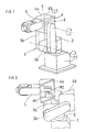
- Fig. 1 is a perspective view showing one embodiment of an articulated robot having a double arm structure according to the present invention;
- Fig. 2 is a view for explaining the opened state of a housing of the articulated robot of Fig. 1;
- Fig. 3 is a perspective view showing a conventional articulated robot having a double arm structure; and
- Fig. 4 is a view for explaining the opened state of a housing of the articulated robot of Fig. 3.
-
- Hereinafter will be described an embodiment of an articulated robot according to the present invention with reference to Figs. 1 and 2. In Figs. 1 and 2, parts similar in constitution to those shown in Fig. 4 are denoted by the same reference numerals.
- A
base 1 is mounted with aturn portion 2 which turns about an axis perpendicular to a mounting surface (not shown) of thebase 1. One end of a first arm piece 3a and that of asecond arm piece 3b are fitted to theturn portion 2 so that thearm pieces 3a and 3b can rotate about the common axis perpendicular to the center of turning axis of theturn portion 2. The first arm piece 3a and thesecond arm piece 3b constitute afirst robot arm 3 in double arm structure. - The first arm piece 3a, serving as one of the arms constituting the
first robot arm 3, is of endoskeletal structure to transmit a drive force, and one end of the first arm piece 3a is rotatably fitted to theturn portion 2. On the other hand, thesecond arm piece 3b, serving as the other of the arms constituting thefirst robot arm 3, is of structure to house cables and/or pipes or the like, and one end of the second arm piece is rotatably supported by theturn portion 2. - A
housing 4a is mounted to the first arm piece 3a at the other end thereof so that it can rotate about an axis perpendicular to the turning axis of theturn portion 2. Thehousing 4a constitutes asecond robot arm 4. A motor M1 and a speed reducer or the like for causing thesecond robot arm 4 to rotate relatively to thefirst robot arm 3, a motor M2 and a speed reducer for causing awrist 5 to rotate, and cables, air pipes and valves or the like for an end effector are housed within thehousing 4a. Incidentally, the structure thereof is similar to that of the prior art. - This embodiment is different from the prior art shown in Figs. 3 and 4 in that the open surface of the
housing 4a of thesecond robot arm 4 according to this embodiment is formed to substantially face thesecond arm piece 3b. Then, a cover 4b for covering the open surface of thehousing 4a is mounted to thehousing 4a with a fixing tool or fixing means such as bolts. - As shown in Fig. 1, each of the
housing 4a and the cover 4b has a shape like that resulting from longitudinally dividing a rectangular parallelepiped box into two parts along one of diagonal lines of a rectangular top surface of the rectangular parallelepiped box. Thus, thehousing 4a and the cover 4b are combined together into a rectangular parallelepiped box. In other words, each of the housing and the cover is composed of upper and lower right-angled triangular plates, and two rectangular side plates each having sides equal in length to the sides making a right angle of each right-angled triangular plate. When the housing is covered with the cover, the housing and the cover takes the shape of a rectangular parallelepiped as a whole. - The cover 4b is rotatably supported by the
second arm piece 3b. As shown in Fig. 1, when the cover 4b is fixed to thehousing 4a through thefixing tool 6, the turning axis of thehousing 4a relative to the first arm piece 3a is in alignment with the turning axis of the cover 4b relative to thesecond arm piece 3b. - Further, the
wrist 5 adapted to mount an end effector to its end is connected to thehousing 4a (the second robot arm 4), similarly to the case in the prior art. - When the
turn portion 2 is caused to rotate relatively to thebase 1, the first andsecond robot arms wrist 5 are also turned together with theturn portion 2. Further, when a drive source (not shown) to drive thefirst robot arm 3 is operated to drive the first arm piece 3a, the first arm piece 3a makes a pivotal motion relative to theturn portion 2 to move thesecond robot arm 4. Further, thesecond arm piece 3b is driven by the first arm piece 3a through thehousing 4a and the cover 4b and makes a pivotal motion together with the first arm piece 3a. When the motor M1 to drive thesecond robot arm 4 is driven, thesecond robot arm 4 makes a pivotal motion relative to the first robot arm 3 (the first arm piece 3a and thesecond arm piece 3b). - The maintenance of equipment such as the motors M1, M2 and speed reducers and parts such as pipes and cables in the
housing 4a is carried out by separating the cover 4b from thehousing 4a in the manner of causing thesecond arm piece 3b to rotate relatively to the first arm piece 3a in the direction opposite to the wrist as shown in Fig. 2 after the removal of thefixing tool 6 such as bolts. Since thesecond arm piece 3b is only rotatably supported by theturn portion 2, it is possible to freely rotate thesecond arm piece 3b as shown in Fig. 2. The cover 4b is separated from thehousing 4a by the pivotal motion of thesecond arm piece 3b to open thehousing 4a. - According to the embodiment as described above, each of the
housing 4a and the cover 4b has a shape like that resulting from longitudinally dividing the rectangular parallelepiped box into two parts along one of diagonal lines of the rectangular top surface, as shown in Fig. 1. Thus, since the rear surface (i.e., the side opposite to the wrist 5), the side surface (i.e., the side opposite to thesecond arm piece 3b), the half of the upper surface and that of the lower surface of thehousing 4a are opened, access to the equipment and parts such as the motors, the speed reducers, the pipes, the cables and the valves housed within thehousing 4a is easily made, thus resulting in ease in maintenance. - Besides, since the cables and the pipes are exposed to the outside when the
housing 4a is opened, there is no need for removal of thesecond arm piece 3b for operation of the cables and pipes as in the case of the prior art, so that the need for disassembling work of thesecond arm piece 3b is eliminated to accordingly facilitate the maintenance. Further, in assembling the robot, step of installing the equipment and parts such as the motors M1, M2 and the speed reducers into thehousing 4a and step of assembling thesecond arm piece 3b are carried out separately from each other, and thereafter the cables and pipes drawn out of thesecond arm piece 3b are connected to the equipment and parts in thehousing 4a, thus, resulting in ease in assembling of the robot. Further, since the cover 4b is mounted to thesecond arm piece 3b, thesecond arm piece 3b fulfills a guide function to easily locate the cover 4b with respect to thehousing 4a. Furthermore, since the partition surface between thehousing 4a and the cover 4b may be formed as a plane, the packing or seal structure of the partition surface may be also easily constructed. - Incidentally, according to the embodiment, while each of the
housing 4a and the cover 4b has the shape like that resulting from longitudinally dividing the rectangular parallelepiped box into two parts along one of diagonal lines of the rectangular top surface, it is to be understood that the housing and the cover are not limited to the above shape. - When a surface adapted to mount the
wrist 5 is only available for the surface adapted to mount the equipment or the like housed in thehousing 4a (the surface adapted to mount the first arm piece 3a is partially required), it is also useful to form the housing only by this surface, while using the other five surfaces (i.e., the upper surface, the lower surface, the opposite side surfaces and the rear surface) for the formation of the cover. Otherwise, the housing may be formed by the surface adapted to mount thewrist 5 and the side surface opposite to thesecond arm piece 3b or the bottom surface, while the other surfaces may be used for the formation of the cover. That is, thehousing 4a may be formed at least by the surface adapted to mount the equipment or the like housed in thehousing 4a, and the surfaces adapted to mount thewrist 5 and the first arm piece 3a, while the other surfaces may be used for the formation of the cover 4b so as to facilitate the access to the equipment in thehousing 4a when thehousing 4a is opened. - As has been described in the foregoing, access to the equipment and the parts housed in the housing may be easily made without disassembling the robot arm or the like, and the maintenance of the equipment and parts described above may be facilitated. Further, the assemblage of the robot is also facilitated to simplify the production process, resulting in the improvement in productivity. Furthermore, since the partition surface between the housing and the cover may be formed as a plane, the packing and seal structure of the partition surface may be easily constructed. Moreover, since positioning of the cover to be done when the cover is mounted to the housing is made by being guided by the arm piece mounted with the cover, the cover can be easily positioned with respect to the housing.
Claims (2)
- An articulated robot, comprising:a first robot arm of double arm structure in which a first arm piece formed as an endoskeletal arm to transmit a drive force is installed parallel to a second arm piece to house cables and/or pipes or the like; anda second robot arm which is rotatably supported, at its one end, by said first robot arm at the end thereof;wherein a housing of said second robot arm is rotatably supported by said first arm piece at the end thereof, a cover of the housing of said second robot arm is rotatably supported by said second arm piece at the end thereof, said cover is fixed to the housing through fixing means, and said housing is permitted to be opened by separating said housing and said cover from each other in the manner of or by causing said second arm piece to rotate relatively to said first arm piece after the removal of said fixing means.
- An articulated robot according to claim 1, wherein each of said housing and said cover is composed of upper and lower right-angled triangular plates, and two rectangular side plates each having one side equal to one of sides making a right angle of each right-angled triangular plate, and said housing and said cover take the shape of a rectangular parallelepiped as a whole when said housing is covered with said cover.
Applications Claiming Priority (2)
| Application Number | Priority Date | Filing Date | Title |
|---|---|---|---|
| JP10375056A JP3001877B1 (en) | 1998-12-14 | 1998-12-14 | Articulated robot |
| JP37505698 | 1998-12-14 |
Publications (2)
| Publication Number | Publication Date |
|---|---|
| EP1010499A1 true EP1010499A1 (en) | 2000-06-21 |
| EP1010499B1 EP1010499B1 (en) | 2003-05-02 |
Family
ID=18504894
Family Applications (1)
| Application Number | Title | Priority Date | Filing Date |
|---|---|---|---|
| EP99309082A Expired - Lifetime EP1010499B1 (en) | 1998-12-14 | 1999-11-16 | Articulated robot |
Country Status (4)
| Country | Link |
|---|---|
| US (1) | US6279413B1 (en) |
| EP (1) | EP1010499B1 (en) |
| JP (1) | JP3001877B1 (en) |
| DE (1) | DE69907381T2 (en) |
Cited By (5)
| Publication number | Priority date | Publication date | Assignee | Title |
|---|---|---|---|---|
| EP1880809A1 (en) * | 2006-07-20 | 2008-01-23 | Fanuc Ltd | Arm structure of industrial robot |
| EP1892064A1 (en) * | 2006-08-24 | 2008-02-27 | Fanuc Ltd | Drive mechanism for industrial robot arm |
| EP2057901A1 (en) | 2007-11-12 | 2009-05-13 | Durand International | Installation for splitting pig carcasses or similar comprising one or more robots |
| EP3189946A1 (en) * | 2016-01-08 | 2017-07-12 | ABB Schweiz AG | An industrial robot with a modular lower arm |
| EP1856367B1 (en) * | 2005-03-11 | 2017-11-08 | Atlas Copco Rock Drills AB | Rotation device for a boom of a mining or constructions work rig, rig and boom |
Families Citing this family (16)
| Publication number | Priority date | Publication date | Assignee | Title |
|---|---|---|---|---|
| US6831436B2 (en) * | 2002-04-22 | 2004-12-14 | Jose Raul Gonzalez | Modular hybrid multi-axis robot |
| WO2006085823A1 (en) * | 2005-02-11 | 2006-08-17 | Abb Ab | A method and a contact panel having contacts protruding through an opening in a cover forming part of an industrial robot |
| US20060261192A1 (en) * | 2005-04-15 | 2006-11-23 | Durr Systems, Inc. | Robotic paint applicator and method of protecting a paint robot having an explosion proof electric motor |
| JP5225658B2 (en) * | 2007-11-09 | 2013-07-03 | 東芝機械株式会社 | Robot for work |
| JP5552329B2 (en) * | 2010-02-10 | 2014-07-16 | 株式会社ダイヘン | Welding robot |
| CN102275158A (en) * | 2010-06-10 | 2011-12-14 | 鸿富锦精密工业(深圳)有限公司 | Robot |
| US9241766B2 (en) * | 2010-12-22 | 2016-01-26 | Intuitive Surgical Operations, Inc. | Alternate instrument removal |
| CN103084293A (en) * | 2011-10-31 | 2013-05-08 | 鸿富锦精密工业(深圳)有限公司 | Robot arm part |
| JP5576911B2 (en) * | 2012-08-20 | 2014-08-20 | ファナック株式会社 | Articulated robot equipped with both-end arm members |
| JP5670588B2 (en) * | 2014-02-28 | 2015-02-18 | 株式会社ダイヘン | Articulated robot |
| JP6068548B2 (en) * | 2015-04-09 | 2017-01-25 | ファナック株式会社 | An articulated robot in which connecting members for connecting the striatum are arranged on the arm |
| ITUB20159345A1 (en) * | 2015-12-23 | 2017-06-23 | Comau Spa | Multi-axis industrial robot, in particular of the SCARA type |
| CN107953363B (en) * | 2017-05-10 | 2021-09-07 | Abb瑞士股份有限公司 | Arm for multi-joint robot and multi-joint robot |
| JP2018187748A (en) * | 2017-05-11 | 2018-11-29 | セイコーエプソン株式会社 | Robot, robot control device, and robot system |
| JP7405588B2 (en) | 2019-12-11 | 2023-12-26 | ファナック株式会社 | Housing and joint mechanism |
| CN112497264A (en) * | 2020-11-30 | 2021-03-16 | 湖南哈工聚能科技有限公司 | Six-axis light cooperative robot |
Citations (3)
| Publication number | Priority date | Publication date | Assignee | Title |
|---|---|---|---|---|
| EP0593786A1 (en) * | 1992-04-28 | 1994-04-27 | Fanuc Ltd. | Cable handling apparatus for arms of industrial robot |
| JPH07124887A (en) * | 1993-10-29 | 1995-05-16 | Fanuc Ltd | Cable treating device for industrial robot |
| JPH08281580A (en) * | 1995-04-13 | 1996-10-29 | Fanuc Ltd | Robot arm of industrial horizontal multi-revolute-joint type robot |
Family Cites Families (3)
| Publication number | Priority date | Publication date | Assignee | Title |
|---|---|---|---|---|
| US4973215A (en) * | 1986-02-18 | 1990-11-27 | Robotics Research Corporation | Industrial robot with servo |
| JPH0957680A (en) * | 1995-08-18 | 1997-03-04 | Tokico Ltd | Industrial robot |
| US5949209A (en) * | 1996-09-11 | 1999-09-07 | Nachi-Fujikoshi Corp. | Explosion-proof painting robot |
-
1998
- 1998-12-14 JP JP10375056A patent/JP3001877B1/en not_active Expired - Fee Related
-
1999
- 1999-11-04 US US09/434,160 patent/US6279413B1/en not_active Expired - Fee Related
- 1999-11-16 EP EP99309082A patent/EP1010499B1/en not_active Expired - Lifetime
- 1999-11-16 DE DE69907381T patent/DE69907381T2/en not_active Expired - Fee Related
Patent Citations (3)
| Publication number | Priority date | Publication date | Assignee | Title |
|---|---|---|---|---|
| EP0593786A1 (en) * | 1992-04-28 | 1994-04-27 | Fanuc Ltd. | Cable handling apparatus for arms of industrial robot |
| JPH07124887A (en) * | 1993-10-29 | 1995-05-16 | Fanuc Ltd | Cable treating device for industrial robot |
| JPH08281580A (en) * | 1995-04-13 | 1996-10-29 | Fanuc Ltd | Robot arm of industrial horizontal multi-revolute-joint type robot |
Non-Patent Citations (2)
| Title |
|---|
| PATENT ABSTRACTS OF JAPAN vol. 1995, no. 08 29 September 1995 (1995-09-29) * |
| PATENT ABSTRACTS OF JAPAN vol. 1997, no. 02 28 February 1997 (1997-02-28) * |
Cited By (6)
| Publication number | Priority date | Publication date | Assignee | Title |
|---|---|---|---|---|
| EP1856367B1 (en) * | 2005-03-11 | 2017-11-08 | Atlas Copco Rock Drills AB | Rotation device for a boom of a mining or constructions work rig, rig and boom |
| NO342029B1 (en) * | 2005-03-11 | 2018-03-12 | Atlas Copco Rock Drills Ab | Rotary device for a boom in a drilling or construction rig, rig and boom |
| EP1880809A1 (en) * | 2006-07-20 | 2008-01-23 | Fanuc Ltd | Arm structure of industrial robot |
| EP1892064A1 (en) * | 2006-08-24 | 2008-02-27 | Fanuc Ltd | Drive mechanism for industrial robot arm |
| EP2057901A1 (en) | 2007-11-12 | 2009-05-13 | Durand International | Installation for splitting pig carcasses or similar comprising one or more robots |
| EP3189946A1 (en) * | 2016-01-08 | 2017-07-12 | ABB Schweiz AG | An industrial robot with a modular lower arm |
Also Published As
| Publication number | Publication date |
|---|---|
| EP1010499B1 (en) | 2003-05-02 |
| JP2000176877A (en) | 2000-06-27 |
| DE69907381D1 (en) | 2003-06-05 |
| US6279413B1 (en) | 2001-08-28 |
| DE69907381T2 (en) | 2004-03-25 |
| JP3001877B1 (en) | 2000-01-24 |
Similar Documents
| Publication | Publication Date | Title |
|---|---|---|
| EP1010499B1 (en) | Articulated robot | |
| US10456908B2 (en) | Multi-axial industrial robot | |
| EP0593786B1 (en) | Cable handling apparatus for arms of industrial robot | |
| US9764483B2 (en) | Robot and manufacturing method of the same | |
| EP3184262B1 (en) | Multi-axis industrial robot, in particular of a scara type | |
| EP1671755A1 (en) | Horizontal articulated robot with upper and lower end effector mounting portions | |
| US6250174B1 (en) | Robot construction | |
| KR102163086B1 (en) | Multi-axis robot apparatus with unequal length forearms, electronic device manufacturing systems, and methods for transporting substrates in electronic device manufacturing | |
| US8413538B2 (en) | Articulated manipulator | |
| EP0665089B1 (en) | Industrial robot | |
| US8231117B2 (en) | Robot system | |
| US20080016979A1 (en) | Arm structure of industrial robot | |
| US20150114161A1 (en) | Robot | |
| JP2821842B2 (en) | Equipment to fix and maintain the glass plate to be formed in place during processing | |
| JP7027774B2 (en) | robot | |
| JPH03213288A (en) | Reconstructable robot arm and reconstruction thereof | |
| US8528191B2 (en) | U-shaped iron core transporting/assembling method, and U-shaped iron core transporting/assembling tank | |
| JP3340456B2 (en) | Industrial articulated robot | |
| JPH07266281A (en) | Robot changing device | |
| JP6798591B2 (en) | Robots, robot systems, robot maintenance methods | |
| JP7069757B2 (en) | Horizontal articulated robot | |
| US20220143814A1 (en) | Reconfigurable controller base for robotic arm | |
| JP6638878B2 (en) | Robots, robot systems, and robot maintenance methods | |
| JPH0985666A (en) | Wrist structure of robot | |
| US11858135B2 (en) | Robot, method of assembling robot, and robot system |
Legal Events
| Date | Code | Title | Description |
|---|---|---|---|
| PUAI | Public reference made under article 153(3) epc to a published international application that has entered the european phase |
Free format text: ORIGINAL CODE: 0009012 |
|
| AK | Designated contracting states |
Kind code of ref document: A1 Designated state(s): DE |
|
| AX | Request for extension of the european patent |
Free format text: AL;LT;LV;MK;RO;SI |
|
| 17P | Request for examination filed |
Effective date: 20000619 |
|
| AKX | Designation fees paid |
Free format text: DE |
|
| GRAH | Despatch of communication of intention to grant a patent |
Free format text: ORIGINAL CODE: EPIDOS IGRA |
|
| GRAH | Despatch of communication of intention to grant a patent |
Free format text: ORIGINAL CODE: EPIDOS IGRA |
|
| GRAA | (expected) grant |
Free format text: ORIGINAL CODE: 0009210 |
|
| AK | Designated contracting states |
Designated state(s): DE |
|
| REF | Corresponds to: |
Ref document number: 69907381 Country of ref document: DE Date of ref document: 20030605 Kind code of ref document: P |
|
| PLBE | No opposition filed within time limit |
Free format text: ORIGINAL CODE: 0009261 |
|
| STAA | Information on the status of an ep patent application or granted ep patent |
Free format text: STATUS: NO OPPOSITION FILED WITHIN TIME LIMIT |
|
| 26N | No opposition filed |
Effective date: 20040203 |
|
| PGFP | Annual fee paid to national office [announced via postgrant information from national office to epo] |
Ref country code: DE Payment date: 20081114 Year of fee payment: 10 |
|
| PG25 | Lapsed in a contracting state [announced via postgrant information from national office to epo] |
Ref country code: DE Free format text: LAPSE BECAUSE OF NON-PAYMENT OF DUE FEES Effective date: 20100601 |