EP1010044B1 - Safety or protection system employing reflective memory and/or diverse processors and communications - Google Patents
Safety or protection system employing reflective memory and/or diverse processors and communications Download PDFInfo
- Publication number
- EP1010044B1 EP1010044B1 EP98928959A EP98928959A EP1010044B1 EP 1010044 B1 EP1010044 B1 EP 1010044B1 EP 98928959 A EP98928959 A EP 98928959A EP 98928959 A EP98928959 A EP 98928959A EP 1010044 B1 EP1010044 B1 EP 1010044B1
- Authority
- EP
- European Patent Office
- Prior art keywords
- signals
- safety
- protection
- subsystems
- processing
- Prior art date
- Legal status (The legal status is an assumption and is not a legal conclusion. Google has not performed a legal analysis and makes no representation as to the accuracy of the status listed.)
- Expired - Lifetime
Links
Images


Classifications
-
- G—PHYSICS
- G06—COMPUTING OR CALCULATING; COUNTING
- G06F—ELECTRIC DIGITAL DATA PROCESSING
- G06F11/00—Error detection; Error correction; Monitoring
- G06F11/07—Responding to the occurrence of a fault, e.g. fault tolerance
- G06F11/16—Error detection or correction of the data by redundancy in hardware
- G06F11/20—Error detection or correction of the data by redundancy in hardware using active fault-masking, e.g. by switching out faulty elements or by switching in spare elements
- G06F11/2002—Error detection or correction of the data by redundancy in hardware using active fault-masking, e.g. by switching out faulty elements or by switching in spare elements where interconnections or communication control functionality are redundant
- G06F11/2007—Error detection or correction of the data by redundancy in hardware using active fault-masking, e.g. by switching out faulty elements or by switching in spare elements where interconnections or communication control functionality are redundant using redundant communication media
-
- G—PHYSICS
- G05—CONTROLLING; REGULATING
- G05B—CONTROL OR REGULATING SYSTEMS IN GENERAL; FUNCTIONAL ELEMENTS OF SUCH SYSTEMS; MONITORING OR TESTING ARRANGEMENTS FOR SUCH SYSTEMS OR ELEMENTS
- G05B9/00—Safety arrangements
- G05B9/02—Safety arrangements electric
- G05B9/03—Safety arrangements electric with multiple-channel loop, i.e. redundant control systems
-
- G—PHYSICS
- G06—COMPUTING OR CALCULATING; COUNTING
- G06F—ELECTRIC DIGITAL DATA PROCESSING
- G06F11/00—Error detection; Error correction; Monitoring
- G06F11/07—Responding to the occurrence of a fault, e.g. fault tolerance
- G06F11/0796—Safety measures, i.e. ensuring safe condition in the event of error, e.g. for controlling element
-
- G—PHYSICS
- G06—COMPUTING OR CALCULATING; COUNTING
- G06F—ELECTRIC DIGITAL DATA PROCESSING
- G06F11/00—Error detection; Error correction; Monitoring
- G06F11/07—Responding to the occurrence of a fault, e.g. fault tolerance
- G06F11/16—Error detection or correction of the data by redundancy in hardware
- G06F11/20—Error detection or correction of the data by redundancy in hardware using active fault-masking, e.g. by switching out faulty elements or by switching in spare elements
- G06F11/2002—Error detection or correction of the data by redundancy in hardware using active fault-masking, e.g. by switching out faulty elements or by switching in spare elements where interconnections or communication control functionality are redundant
- G06F11/2012—Error detection or correction of the data by redundancy in hardware using active fault-masking, e.g. by switching out faulty elements or by switching in spare elements where interconnections or communication control functionality are redundant and using different communication protocols
-
- G—PHYSICS
- G06—COMPUTING OR CALCULATING; COUNTING
- G06F—ELECTRIC DIGITAL DATA PROCESSING
- G06F11/00—Error detection; Error correction; Monitoring
- G06F11/07—Responding to the occurrence of a fault, e.g. fault tolerance
- G06F11/14—Error detection or correction of the data by redundancy in operations
- G06F11/1479—Generic software techniques for error detection or fault masking
- G06F11/1487—Generic software techniques for error detection or fault masking using N-version programming
-
- G—PHYSICS
- G06—COMPUTING OR CALCULATING; COUNTING
- G06F—ELECTRIC DIGITAL DATA PROCESSING
- G06F11/00—Error detection; Error correction; Monitoring
- G06F11/07—Responding to the occurrence of a fault, e.g. fault tolerance
- G06F11/16—Error detection or correction of the data by redundancy in hardware
- G06F11/18—Error detection or correction of the data by redundancy in hardware using passive fault-masking of the redundant circuits
- G06F11/182—Error detection or correction of the data by redundancy in hardware using passive fault-masking of the redundant circuits based on mutual exchange of the output between redundant processing components
-
- G—PHYSICS
- G06—COMPUTING OR CALCULATING; COUNTING
- G06F—ELECTRIC DIGITAL DATA PROCESSING
- G06F11/00—Error detection; Error correction; Monitoring
- G06F11/07—Responding to the occurrence of a fault, e.g. fault tolerance
- G06F11/16—Error detection or correction of the data by redundancy in hardware
- G06F11/18—Error detection or correction of the data by redundancy in hardware using passive fault-masking of the redundant circuits
- G06F11/187—Voting techniques
- G06F11/188—Voting techniques where exact match is not required
Definitions
- This invention is directed to a safety or protection system and, more particularly, to such a system for a critical process such as a nuclear power plant.
- duplication may take the form of redundant systems.
- duplicate sensors, controllers, actuators and communication channels may be provided in separate independent subsystems to perform the identical function.
- the hardware and logic are identical in each of the subsystems.
- multiple, identical channels are provided to generate independent control signals which are voted to determine the final control signal to be applied to a single component.
- protection systems which include four separate channels, each with its own sensors and controllers for generating a reactor trip signal in response to certain conditions in the plant. Voting logic trips the plant only if, for instance, two or more of the four channels generate a channel trip signal.
- a common mode failure it is meant, simultaneous, similar failures in corresponding elements, either hardware or software, of the system.
- each safety or protection, subsystem comprises reflective memory means for communicating the second signals between that safety or protection subsystems and another of the safety or protection subsystems, and in that the reflective memory means of each subsystem is adapted to store representations of one second signal from the division of first signals it receives and of at least another second signal, from another of the safety or protection subsystems, derived from the corresponding division of first signals said another safety or protection subsystem receives.
- the present invention provides a safety protection system for a critical process, said critical process having a characteristic, a plurality of parameters each of which is representative of said characteristic, and a plurality of divisions, of first signals, said safety or protection system comprising, at least two safety or protection sub-systems each of which comprises, first means for monitoring a first one of the parameters and providing a second signal representative thereof, second means for monitoring a second one of the parameters and providing a third signal representative thereof, first processing means and second processing means.
- the invention is characterised in that said first means monitoring a first one of the parameters provides said second signal representative thereof to a first one of the divisions of first signals, said second means for monitoring a second one of the parameters provides said third signal representative thereof to a second one of the divisions of first signals, said first processing means is configured to process the first division and the second signal and provide a first output said second processing means is configured to process the second division and the third signal and provide a second output, with said second processing means being substantially different from said first processing means, and said first and second outputs being redundant relative to said characteristic, and in that each said safety or protection sub-system further comprises, first communication means for communicating the first division, the second signal and the first output to the others of said at least two safety or protection sub-systems, second communication means for communicating the second division, the third signal and the second output to the others of said at least two safety or protection sub-systems, with said second communication means being substantially different from said first communication means, said safety or protection system further comprising means for combining the first and second outputs of each of said safety
- signal shall expressly include, but not be limited to any input or output utilised for protection, safety, control and/or monitoring such as, for example, electrical or analog signals, digital signals, command signals, status signals, discrete signals, combined or compound signals, serial signals, or serial messages.
- digital signal shall expressly include, but not be limited to boolean signals ( e . g ., true or false, one or zero) and digitised analog signals.
- vision shall expressly include, but not be limited to one or more input signals.
- train shall expressly include, but not be limited to one or more output signals.
- the system 2 includes three divisions 6,8,10 of first signals, such as electrical signals; three protection subsystems 12,14,16; and two safety subsystems 18,20.
- each of the three protection subsystems 12,14,16 receives a corresponding one of the divisions 6,8,10 of first signals and produces a corresponding plurality of second signals 17A,17B,17C, such as digital signals, therefrom.
- the system 2 also includes a reflective memory subsystem 22 for communicating the second signals 17A,17B,17C between the protection subsystems 12,14,16 and/or the safety subsystems 18,20.
- the protection subsystems 12,14,16 may include integrated protection logic (IPL) for reactor shutdown (trip or scram) or emergency core cooling logic (ECCL), as understood by those skilled in the art, for the nuclear power plant.
- the safety subsystems 18,20 may include a safety monitoring system (SMS), which is used for post accident monitoring of critical plant parameters, as also understood by those skilled in the art.
- SMS safety monitoring system
- information to the reactor operator is carried by the reflective memory subsystem 22 to the safety monitoring systems 18,20 in respective main control room (MCR) and emergency control room (ECR), with redundancy provided through the separate systems 18,20 in these two different control rooms.
- a gateway 24 may be provided for connection between the reflective memory subsystem 22 and a non-safety redundant highway 25 to provide the second signals 17A,17B,17C, such as protection system process data and status information, to a plant computer system (not shown).
- the second signals 17A,17B,17C may be time tagged at the gateway 24 by a plant master time signal from the highway 25.
- the information communicated to the plant computer system may be used for post event monitoring and/or evaluation.
- a safety system 26 includes two divisions 28,30 of first signals, such as electrical signals; and two safety subsystems 32,34.
- each of the two safety subsystems 32,34 receives a corresponding one of the divisions 28,30 of first signals and produces a corresponding plurality of second signals 35A,35B, such as digital signals, therefrom.
- the system 2 also includes a reflective memory subsystem 36 for communicating the second signals 35A,35B between the safety subsystems 32,34.
- the exemplary reflective memory subsystem 22 includes, for each of the protection subsystems 12,14,16, three memory storage subsystems 38,40,42; three communication subsystems 44,46,48; and one of three communication channels 50,52,54.
- the memory storage subsystem 38A stores the second signals 56 of protection subsystem 12.
- the memory storage subsystems 40B,42C of protection subsystems 14,16 store the second signals 58,60 of those protection subsystems 14,16, respectively.
- the communication subsystem 44A retrieves the second signals 56 from the memory storage subsystem 38A of the protection subsystem 12 and sends third digital signals 62A, representative of the second signals 56, from the protection subsystem 12 on the communication channel 50 to the other two protection subsystems 14,16.
- the other two communication subsystems 44B,44C of the respective other two protection subsystems 14,16 receive the third signals 62A from the communication channel 50.
- these communication subsystems 44B,44C store second digital signals 64,66, representative of the third signals 62A, in the memory storage subsystems 38B,38C of the other two protection subsystems 14,16, respectively.
- the communication subsystem 44A functions as a master (M) of the communication channel 50 and the communication subsystems 44B,44C function as slaves (S) of the master on that communication channel 50.
- the communication subsystems 46B,48C function as masters of the respective communication channels 52,54 and the communication subsystems 46A-46C,48A-48B function as slaves of the master on those communication channels 52,54, respectively.
- the three communication channels 50,52,54 communicate the third digital signals 62A,62B,62C, representative of the second digital signals 56,58,60, from one of the protection subsystems 12,14,16 to the other pair of protection subsystems 14-16,12-16,12-14, respectively.
- the third digital signals 62A,62B,62C are stored in pairs of memory subsystems 38B-38C,40A-40C,42A-42B corresponding to pairs of communication subsystems 44B-44C,46A-46C,48A-48B, respectively.
- the communication subsystems 46A,48A store other second digital signals 65,67 representative of the third signals 62B,62C in corresponding memory subsystems 40A,42A, respectively.
- each of the reflective memories (RM) 68 of Figures 1-2 and 68A,68B,68C of Figure 3 is a Model No. 5576 reflective memory marketed by VME Microsystems International, Inc., although the invention is applicable to any reflective memory subsystem in which a first memory subsystem sends or reflects memory information to one or more other memory subsystems.
- the communication channel 50 forms an interface between the protection subsystem 12 and the other protection subsystems 14,16.
- the protection subsystem 12 communicates with the protection subsystems 14,16 through the reflective memories 68A,68B,68C which reside in the respective protection subsystems 12,14,16.
- the reflective memories 68A,68B,68C of the protection subsystems 12,14,16 permit protocol-less data transfer therebetween.
- the communication channel 50 preferably is a fiber optic ring communications network, although the invention is applicable to a wide variety of communication channels (e . g ., fiber optic datalinks, coaxial datalinks, coaxial networks).
- the exemplary communication channel 50 includes two counter-rotating fiber optic rings 70,72. These fiber optic rings 70,72, in addition to providing redundant data transfer paths, electrically isolate each of the divisions of electrical signals 6,8,10 of the protection subsystems 12,14,16 of Figure 1 from the divisions of electrical signals 6,8,10 of the other protection subsystems 12,14,16 in order that the channel 50 is reaction free.
- the information from the source memory e .
- 68A bypasses the failed memory in order that all other memories (e.g. , 68C) connected to the channel 50 continue to receive the information. Also, in the event of a failure in both of the rings 70,72 ( e . g ., at point 73 on the left side of Figure 4), the information from the source memory (e.g., 68A) is still sent to the destination memories ( e.g., 68B, 68C) through ring 72 (at the right side of Figure 4).
- the exemplary protection subsystem 74 protects a critical process 79, such as the exemplary nuclear reactor pressure vessel, and is part of a primary reactor protection system 80 which includes two other protection subsystems 81,82.
- the critical process 79 has one or more characteristics 83, such as conditions of the pressure vessel; and a plurality of parameters 84,86, each of which is representative of the characteristic 83.
- These parameters 84,86 i . e ., temperature (T) and level (L)
- T temperature
- L level
- the pressure vessel 79 includes one or more temperature sensors (TS) 88, which monitor or sense temperatures of the vessel 79; and one or more level sensors (LS) 90, which monitor cooling water levels in the vessel 79.
- the sensors 88 and 90 provide an electrical signal 92 representative of the temperature and an electrical signal 94 representative of the level, respectively.
- the signals 92,94 are combined in the divisions 96,98 of electrical signals for input by the processors 76,78, respectively.
- the divisions 96,98 permit the respective processors 76,78 to monitor various conditions of the critical process 79 and provide corresponding protection functions therefor ( e . g ., preventing severe core damage, such as core melt; maintaining the integrity of the reactor coolant system (not shown); and allowing operating staff to safety shut down and monitor the nuclear power plant (not shown) including necessary remedial actions for frequent events).
- the processor (A) 76 processes the first division 96, including the signal 92, and provides a first protection train, such as outputs 100,102, therefrom.
- the processor (B) 78 processes the second division 98, including the signal 94, and provides a second protection train, such as outputs 104,106, therefrom.
- the processor (A) 76 and parameter 84 are substantially different from the processor (B) 78 and parameter 86, with the first outputs 100,102 and second outputs 104,106 being redundant relative to the characteristic 83.
- the diverse processors 76,78 employ different respective parameters 84,86 and substantially different mechanisms, as explained in greater detail below and in connection with Figures 6-7, to provide similar respective protection outputs 100,102 and 104,106, which are redundant relative to the characteristic 83. In this manner, a variety of common mode failures between the redundant processors 76,78 are obviated.
- the voting mechanisms 108,110,112 combine the outputs 100,102,104,106 to effect a safety or protection function, such as IPL for a nuclear reactor trip, for the critical process 79.
- voting mechanisms 110 and 112 are interconnected with non-programmable logic (not shown) and respectively provide: (1) actuating signals to dedicated reactor trip switchgear (not shown) and actuating signals to turbine trip logic; and (2) actuating signals to engineered safety features equipment (not shown) through such non-programmable logic.
- the protection subsystem 74 is designed to be highly reliable and easily maintained. Availability is provided by employing fault-tolerant design principles, including sufficient redundancy and independence within the subsystem architecture, and system test features. Maintainability is facilitated through the use of two-out-of-three trip logic in the voting mechanisms 110,112.
- a trip condition exists within one of the protection subsystems 74,81,82, then a logic trip is generated and output to the other two of such protection subsystems.
- a trip is generated and the associated dedicated two AC and two DC reactor trip breakers (not shown) are opened.
- These reactor trip breakers are wired in a matrix such that two sets (of both the AC and DC breakers) must register a two-out-of-three trip before an actual reactor trip occurs.
- three redundant communication channels 114A-114B,116A-116B,118A-118B are provided between the subsystems 74,81,82.
- one set of the channels e.g. , 114B, 116B, 118B
- the other set of the channels e.g. , 114A,116A,118A
- employs a diverse communication channel such as conventional reaction free point-to-point fiber optic datalinks.
- each redundant set of the communication channels 114A-114B,116A-116B,118A-118B internal redundancy is implemented through the three protection subsystems 74,81,82, with the diverse processors 76,78 of each of these protection subsystems connected to one set of the three redundant communication channels 114A-116A-118A,114B-116B-118B.
- each of the protection subsystems 74,81,82 may remain in operation and, hence, actuate its outputs on a real initiating event.
- each parameter is sensed three times, once for each of the subsystems 74,81,82.
- the processors 76,78 convert the sensor analog signals 120,122 to corresponding digital (D) signals 124,126, respectively.
- the communication channel 114A transmits the digital signal 124, along with other digital signals corresponding to the first division 96, the signal 92 and the outputs 100,102, to the corresponding processor A of the other two protection subsystems 81,82.
- the communication channel 114B transmits the digital signal 126, along with other digital signals corresponding to the second division 98, the signal 94 and the outputs 104,106, to the corresponding processor B of the other two protection subsystems 81,82.
- each of the processors A,B of each of the subsystems 74,81,82 the three ( i . e ., one from that processor and two from the other two corresponding processors of the other two protection subsystems) digital sensor values are compared using an irrationality test algorithm as discussed below in connection with Figure 6.
- the protection subsystem 74 may also include a neutron monitoring system (NMS) 128.
- the NMS 128 interfaces with neutron detectors (not shown), converts neutron signals from the detectors to digital values, and communicates these digital values to the processor 76.
- the processor 76 includes a functional processor 130 which preferably has a first microprocessor ( ⁇ P) 132 (e . g ., an 80486 marketed by Intel), a first software strategy (S/W) 134 for execution by the first microprocessor 132, and a suitable interface to a first computer bus 136 (e.g., an IEEE Standard 796 computer bus ( i.e., Multibus)).
- ⁇ P microprocessor
- S/W software strategy
- the processor 76 employs a philosophy of distributed processing in which various tasks are assigned to standardized modules in order that the engineering design of any given module may be handled as simply as possible.
- the general purpose "host” functional processor 130 provides the requisite specific protection functions, and an array of generic "slave" modules 138,140,142,144,146,148,150 perform respective exemplary functions such as: (1) analog input signal conditioning (e.g., powering sensors SA, analog multiplexing, analog filtering, analog signal conversion); (2) data highway data communications; (3) datalink data communications; (4) analog-to-digital (AID) conversion; (5) parallel digital input/output (I/O) handling; (6) diagnostics for monitoring the health of the computer bus 136; and (7) other serial I/O scanning.
- the exemplary processor 76 processes the signals 120 from the sensors SA and the communication channels 164,166.
- microprocessors on some or all of these slave modules reduce the computing burden of the functional processor 130, thereby providing more processing power to perform the protection tasks.
- microprocessor interrupts are not employed in the software 134 which is designed, verified and validated in accordance with IEC Standards 880 and 987, and IEEE Standard 7-4.3.2.
- diagnostic and initialization software is run and, then, the functional processor 130 runs a continuously repeating execution loop. Every loop, a portion of loop diagnostic tests are run.
- One or more of the exemplary process sensors SA may be powered by the analog input signal conditioning module 138 which typically receives one or more conventional (e . g ., 4 to 20 mA range) signals 120 therefrom.
- the module 138 provides a surge withstand capability and converts the exemplary 4 to 20 mA range signals to conventional 0 to 5 V range signals 152.
- the AID module 144 converts one or more of the analog signals 152 to corresponding digital sensor values 154.
- the functional processor 130 reads the digital sensor values 154 from memory (not shown) of the A/D module 144 through the computer bus 136.
- the functional processor 130 converts the digital sensor values 154 to corresponding process values having engineering units (e.g., 123°C).
- the process values are transmitted over the computer bus 136 to the datalink controller module 142.
- the datalink controller module 142 is connected to an optical transmitter card 156 which interfaces to output fiber optic communication channels 158,160 of the communication channels 116A,118A for the respective protection subsystems 81,82 of Figure 5.
- Corresponding digital sensor values for the same parameter are received by the datalink controller module 142 which is also connected to an optical receiver card 162.
- the card 162 interfaces to input fiber optic communication channels 164,166 of the communication channels 116A,118A for the respective protection subsystems 81,82.
- fiber optic datalinks are employed to transmit and receive information between the processors (A) 76 of each of the protection subsystems 74,81,82 of Figure 5.
- the process values from the other two protection subsystems 81,82 are received by the functional processor 130 over the computer bus 136 from the datalink controller module 142.
- the functional processor 130 employs the irrationality test algorithm in its software 134 to calculate a difference between each of the three pairs ( i.e., from protection subsystems 74-81,81-82,74-82) of the digital sensor values and to compare this difference to a limit. A digital sensor value which differs from the other two is rejected and the remaining two are averaged. In turn, this average is compared to a protection setpoint to produce a partial trip signal (either true or false). If the difference between each pair of the digital sensor values exceeds the limit, then the result is interpreted as a partial trip from that functional processor 130. If none of the differences exceeds the limit, then the three digital sensor values are averaged and the resulting average is compared to the protection setpoint. In this manner, the functional processor 130 averages the three digital sensor values, while still rejecting any value differing from the others by more than a predetermined amount, and compares the average with the protection setpoint.
- the functional processor 130 directs the parallel I/O module 146 to output a suitable digital signal 167 to signal conditioning card 168.
- the output 169 of the card 168 de-energizes relay coil (R) 170 of voting relay card 171 which opens normally open contacts 172,174.
- These contacts 172,174 are in series with contacts 176,178, respectively, operated by the processor (B) 76 of Figure 7.
- the pair of series contacts 172-176,174-178 are connected in a two-out-of-three matrix in the voting mechanism 112 of Figure 5 with another train, such as contact pairs 180,181, from the other two protection subsystems 81,82, respectively, in order to open reactor trip breakers (not shown) at two different actuation points and to drop rods (not shown) through control rod drive system electronics (not shown) for a third actuation point.
- the output signals 102,106 of the three protection subsystems 74,81,82 of Figure 5 are voted two-out-of-three (2/3) in the voting mechanism 112.
- the data highway controller module 140 connects to an optical highway interface card 182.
- This card 182 connects to a dual counter-rotating ring highway 183, such as an optical Ethernet highway.
- the highway 183 includes signals for emergency core cooling and diesel load sequencing which are transmitted to emergency core cooling logic cabinets (not shown).
- an automatic tester subsystem 184 Connected to the processor 76 is an automatic tester subsystem 184.
- the automatic tester subsystem 184 is disconnected from the processor 76 by keyswitch and password through an interface panel 186. In that mode, the automatic tester subsystem 184 can read information from, but cannot write to, the processor 76 and protection subsystem 74.
- the automatic tester subsystem 184 includes a functional processor 130'; four slave modules 140',142',146',148'; and a computer bus 136' which perform similar functions as the respective functional processor 130; four slave modules 140,142,146,148; and computer bus 136 of the processor 76.
- the functional processor 130' outputs its own internally generated digital sensor signals 190 over the bus 136' to a digital-to-analog (D/A) converter module 192.
- D/A converter module 192 outputs analog sensor signals 194 to the signal conditioning module 138 for use in place of the signals 120.
- the fiber optic communication channels 164,166 from respective protection subsystems 81,82 of Figure 5 are also disconnected from the optical receiver card 162 by the datalink controller 142' of the automatic tester subsystem 184 which substitutes its own internally generated datalink messages 196.
- the datalink controller 142' also receives datalink messages 198 from the optical transmitter card 156 which are sent by the datalink controller 142 of the processor 76.
- the functional processor 130 continues its normal execution loop, totally unaware that it is being tested.
- the simulated analog sensor signals 194 are ramped up and down over their full range in order to verify proper operation of the protection setpoints and protection algorithms of the software 134 and to exercise all possible combinations of protection logic.
- the accuracy of the A/D conversion performed by A/D module 144 is checked by the automatic tester subsystem 184 as well as the time response of the processor 76.
- Feedback to the automatic tester subsystem 184 is provided from the signal conditioning card 168 through parallel I/O module 146' for reactor trip, control rod insertion, and rod withdrawal block functions, and from the card 182 through data highway controller module 140' for the dual counter-rotating ring highway 183. While the processor (A) 76 is being tested, the processor (B) 78 continues to operate normally, essentially keeping all three protection subsystems 74,81,82 of Figure 5 active.
- the processor 78 includes a functional processor 200 which preferably has a second microprocessor ( ⁇ P) 202 (e.g. , 68040 marketed by Motorola), a second software strategy (S/W) 204 for execution by the second microprocessor 202, and a suitable interface to a second computer bus 206 ( e . g ., an IEEE Standard 1014 computer bus ( i . e ., VME)).
- ⁇ P microprocessor
- S/W software strategy
- VME IEEE Standard 1014 computer bus
- the hardware and software design of the processor 78 are preferably performed by an independent design team not involved in the design process of the processor 76. Accordingly, there are substantial differences between the processor 76 of Figure 6 and the processor 78 of Figure 7, although the invention is applicable to diverse processors having fewer or greater differences to preclude various common mode failures.
- Each postulated trip initiating event for the critical process 79 of Figure 5 is sensed by two diverse functions which are processed in separate diverse processors 76,78 which are coded differently.
- One or more of the exemplary process sensors SB of Figure 7, which are different from the sensors SA of Figure 6, may be powered by the analog input signal conditioning module 208 which typically receives one or more conventional analog signals (e . g ., 4 to 20 mA, RTD, thermocouple) 122 therefrom.
- the exemplary module 208 provides a surge withstand capability and converts the analog signals 122 to conventional 0 to 5 V ranee signals 210.
- An A/D module 212 converts one or more of the analog signals 210 to corresponding digital sensor values 214.
- the functional processor 200 reads the digital sensor values 214 from memory (not shown) of the A/D module 212 through the computer bus 206.
- the functional processor 200 converts the digital sensor values 214 to corresponding process values 215 having engineering units (e . g ., 8m (27 feet)).
- the process values 215, in turn, are transmitted over the computer bus 206 to the reflective memory (RM) 68A which communicates these values over the communication channel 50 as discussed above in connection with Figure 3.
- Corresponding digital sensor values for the same parameter are received by the reflective memories 216,218 of the communication channels 52,54 from the protection subsystems 81,82 of Figure 5, respectively.
- the reflective memory subsystem 22 of Figure 1 is employed to transmit and receive information between the processors (B) 78 of each of the protection subsystems 74,81,82 of Figure 5.
- the process values from the other protection subsystems 81,82 are received by the functional processor 200 over the computer bus 206 from the reflective memories 216,218.
- the functional processor 200 employs an irrationality test algorithm in its software 204 and performs the requisite protection algorithms employing the signals 122. If the protection setpoint is exceeded (either high or low depending on the algorithm); the functional processor 200 directs a trip signal 219 to a digital output module 220 over the computer bus 206. The output 221 of the module 220, in turn, de-energizes relay coil (R) 170' of voting relay card 171', which is identical to the card 171 used in conjunction with the processor 76 of Figure 6.
- R relay coil
- the voting relay cards 171,171' and the voting mechanisms 108,110,112 of Figure 5 have components, such as the relay coils 170,170' and contacts 172,174,176,178, which are different than the other components of processors 76,78 and the sensors SA,SB, and which have a probability of failure ( e . g ., related to the mean time between failure) which is substantially less than the probability of failure of such other components.
- ECCL emergency core cooling logic
- bus diagnostic module 148 of Figure 6 Unlike the bus diagnostic module 148 of Figure 6, a separate bus diagnostic module is not employed in the processor 78. All diagnostic functions, including bus diagnostics, are preferably performed by the functional processor 200. Also, microprocessor interrupts are preferably not employed in the software 204 which is designed, verified and validated in accordance with IEC Standards 880 and 987, and IEEE Standard 7-4.3.2. On power up, diagnostic and initialization software is run and, then, the functional processor 200 runs a continuously repeating execution loop. Every loop, a portion of loop diagnostic tests are run. Although some of the software functions between the functional processor 130 of Figure 5 and the functional processor 200 are similar, as discussed above, different coding languages and design teams are preferably employed for the software 134 of Figure 5 and the software 204.
- an automatic tester 226 is connected to the processor 78.
- the automatic tester subsystem 226 receives information from local VME bus 206'.
- the VME buses 206,206' are interconnected through suitable VME bus adapters (BA) 230,232,
- the automatic tester subsystem 226 is a slave on the VME bus 206.
- the protection subsystem 74 of Figure 5 is not being tested, the automatic tester subsystem 226 is disconnected from the processor 78 by keyswitch and password through an interface panel 228.
- the automatic tester subsystem 226 can read information from the processor 78 and the protection subsystem 74 but cannot write to them. Similarly, the functional processor 200 can write information to the automatic tester subsystem 226, but the automatic tester subsystem 226 cannot write to the VME bus 206. During periodic testing, the normal sensor inputs 122 to the signal conditioner 208 are disconnected by the automatic tester subsystem 226 and test signals 234 are substituted therefor.
- the automatic tester subsystem 226 includes a suitable test processor 236 (e . g ., based on a Motorola 68040 microprocessor) having a local processor bus 238 connected to a D/A converter 240 which provides the signals 234. Data from the other protection subsystems 81,82 of Figure 5 is simulated in the shared memory 242 of the test processor 236 which has a suitable interface to the computer bus 206'.
- a suitable test processor 236 e . g ., based on a Motorola 68040 microprocessor
- D/A converter 240 which provides the signals 234.
- Data from the other protection subsystems 81,82 of Figure 5 is simulated in the shared memory 242 of the test processor 236 which has a suitable interface to the computer bus 206'.
- the functional processor 200 looks for a test flag in the shared memory 242. When this test flag appears, the functional processor 200 reads simulated data for the other two protection subsystems 81,82 from the shared memory 242 instead of from the reflective memories 216,218.
- the test flag which is set by the test processor 236, operates as a soft test switch. Following testing, this soft test switch is returned to the normal ( i . e ., receive data from the communication channels 52,54) position.
- simulated input signals are ramped up and down over their full range verifying accuracy, protection setpoints and protection system function ( e . g ., logic combinations, time dependant functions).
- microprocessors other processors known to those skilled in the art such as, for example, microcomputers, mini-computers or mainframe computers may be employed.
- modules, cards and computer buses, other components e . g ., integrated circuits, sub-modules, sub-cards
- interconnection mechanisms e . g ., printed circuit boards, processor buses, integrated circuit connections
Landscapes
- Engineering & Computer Science (AREA)
- Theoretical Computer Science (AREA)
- Physics & Mathematics (AREA)
- General Physics & Mathematics (AREA)
- Quality & Reliability (AREA)
- General Engineering & Computer Science (AREA)
- Automation & Control Theory (AREA)
- Safety Devices In Control Systems (AREA)
- Hardware Redundancy (AREA)
- Train Traffic Observation, Control, And Security (AREA)
- Testing And Monitoring For Control Systems (AREA)
- Storage Device Security (AREA)
Abstract
Description
- This invention is directed to a safety or protection system and, more particularly, to such a system for a critical process such as a nuclear power plant.
- Many safety or protection systems require duplication in at least some portions of the system for safety and reliability. This duplication may take the form of redundant systems. For example, duplicate sensors, controllers, actuators and communication channels may be provided in separate independent subsystems to perform the identical function. Typically, in such a redundant case, the hardware and logic are identical in each of the subsystems.
- In other cases, multiple, identical channels are provided to generate independent control signals which are voted to determine the final control signal to be applied to a single component. For instance, in a nuclear power plant, it is common to have protection systems which include four separate channels, each with its own sensors and controllers for generating a reactor trip signal in response to certain conditions in the plant. Voting logic trips the plant only if, for instance, two or more of the four channels generate a channel trip signal. In this instance also, it is conventional to have identical hardware and logic in each channel, thereby providing redundancy. See, for example, U.S. Patent No. 4,804,515.
- There is a growing concern over common mode failures in redundant safety or protection systems. By a common mode failure, it is meant, simultaneous, similar failures in corresponding elements, either hardware or software, of the system.
- One application for which these concerns are raised is the retrofitting of existing process control systems, like some existing nuclear power plants, where it is desired to control a single component with commands from two separate subsystems.
- As disclosed in U.S. Patent Application Serial No. 08/557,532, filed November 14, 1995, it is known in prior art instrumentation and control systems to utilise diverse redundant primary and backup control mechanisms, in which the processors and/or the software utilised therein are different, in order to preclude common mode failures. In the case of control mechanisms incorporating digital processors, different types of processors (e.g., from different manufacturers) are used to run different routines (e.g., implemented in different software languages) implementing common algorithms. Although diverse redundant control mechanisms are known, further improvements are possible.
- As disclosed in U.S. Patent Application Serial No. 08/628,536, filed April 4, 1996, it is also knows to employ reflective memories for transmitting sensor signals and control signals between a modelling or simulation system and a stimulation system for such modelling or simulation system. General information on mirrored memory and redundant control systems can be found in EP-A-0 717 358 and WO-A-93/25965.
- There is a need, therefore, for an improved safety or protection system which minimises the possibility of common mode failures.
- This and other needs are satisfied by the invention which is directed to a safety or protection system comprising a plurality of divisions of first signals; a plurality of safety or protection subsystems each of which receives a corresponding one of the divisions of first signals and produces a corresponding plurality of second signals therefrom. The system is characterised in that each safety or protection, subsystem comprises reflective memory means for communicating the second signals between that safety or protection subsystems and another of the safety or protection subsystems, and in that the reflective memory means of each subsystem is adapted to store representations of one second signal from the division of first signals it receives and of at least another second signal, from another of the safety or protection subsystems, derived from the corresponding division of first signals said another safety or protection subsystem receives.
- In another aspect, the present invention provides a safety protection system for a critical process, said critical process having a characteristic, a plurality of parameters each of which is representative of said characteristic, and a plurality of divisions, of first signals, said safety or protection system comprising, at least two safety or protection sub-systems each of which comprises, first means for monitoring a first one of the parameters and providing a second signal representative thereof, second means for monitoring a second one of the parameters and providing a third signal representative thereof, first processing means and second processing means. The invention is characterised in that said first means monitoring a first one of the parameters provides said second signal representative thereof to a first one of the divisions of first signals, said second means for monitoring a second one of the parameters provides said third signal representative thereof to a second one of the divisions of first signals, said first processing means is configured to process the first division and the second signal and provide a first output said second processing means is configured to process the second division and the third signal and provide a second output, with said second processing means being substantially different from said first processing means, and said first and second outputs being redundant relative to said characteristic, and in that each said safety or protection sub-system further comprises, first communication means for communicating the first division, the second signal and the first output to the others of said at least two safety or protection sub-systems, second communication means for communicating the second division, the third signal and the second output to the others of said at least two safety or protection sub-systems, with said second communication means being substantially different from said first communication means, said safety or protection system further comprising means for combining the first and second outputs of each of said safety or protection sub-systems to effect a safety or protection function for said critical process.
- A full understanding of the invention can be gained from the following description of the preferred embodiment when read in conjunction with the accompanying drawings in which:
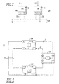
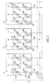
- Figure 3 is a block diagram of a protection system employing reflective memories in accordance with another embodiment of the invention;
- Figure 4 is a block diagram of a counter-rotating ring communication subsystem;
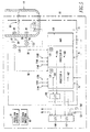
- Figure 5 is a block diagram of an example of a protection subsystem employing diverse processors;
- Figure 6 is a functional block diagram of one of the diverse processors of Figure 5; and
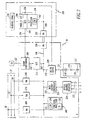
- Figure 7 is a functional block diagram of the other diverse processor of Figure 5.
-
- As employed herein, the term "signal" shall expressly include, but not be limited to any input or output utilised for protection, safety, control and/or monitoring such as, for example, electrical or analog signals, digital signals, command signals, status signals, discrete signals, combined or compound signals, serial signals, or serial messages.
- As employed herein, the term "digital signal" shall expressly include, but not be limited to boolean signals (e.g., true or false, one or zero) and digitised analog signals.
- As employed herein, the term "division" shall expressly include, but not be limited to one or more input signals.
- As employed herein, the term "train" shall expressly include, but not be limited to one or more output signals.
- Referring to Figure 1, a protection and
safety system 2 for a critical process 4, such as a nuclear power plant, is illustrated. Thesystem 2 includes threedivisions 6,8,10 of first signals, such as electrical signals; threeprotection subsystems safety subsystems protection subsystems divisions 6,8,10 of first signals and produces a corresponding plurality ofsecond signals system 2 also includes areflective memory subsystem 22 for communicating thesecond signals protection subsystems safety subsystems - As a non-limiting example, the protection subsystems 12,14,16 may include integrated protection logic (IPL) for reactor shutdown (trip or scram) or emergency core cooling logic (ECCL), as understood by those skilled in the art, for the nuclear power plant. The
safety subsystems reflective memory subsystem 22 to thesafety monitoring systems separate systems - As shown in Figure 1, a
gateway 24 may be provided for connection between thereflective memory subsystem 22 and a non-safetyredundant highway 25 to provide thesecond signals second signals gateway 24 by a plant master time signal from thehighway 25. The information communicated to the plant computer system may be used for post event monitoring and/or evaluation. - As illustrated in Figure 2, a
safety system 26 includes twodivisions safety subsystems safety subsystems divisions second signals 35A,35B, such as digital signals, therefrom. Thesystem 2 also includes areflective memory subsystem 36 for communicating thesecond signals 35A,35B between thesafety subsystems - Operation of the three-channel
reflective memory subsystem 22 of Figure 1 and the two-channelreflective memory subsystem 36 of Figure 2 will be understood from reference to Figures 3 and 4. The exemplaryreflective memory subsystem 22 includes, for each of theprotection subsystems memory storage subsystems communication subsystems communication channels memory storage subsystem 38A stores thesecond signals 56 ofprotection subsystem 12. Similarly, thememory storage subsystems protection subsystems second signals protection subsystems - The
communication subsystem 44A retrieves thesecond signals 56 from thememory storage subsystem 38A of theprotection subsystem 12 and sends thirddigital signals 62A, representative of thesecond signals 56, from theprotection subsystem 12 on thecommunication channel 50 to the other twoprotection subsystems communication channel 50, the other twocommunication subsystems 44B,44C of the respective other twoprotection subsystems third signals 62A from thecommunication channel 50. In turn, thesecommunication subsystems 44B,44C store seconddigital signals third signals 62A, in thememory storage subsystems protection subsystems communication subsystem 44A functions as a master (M) of thecommunication channel 50 and thecommunication subsystems 44B,44C function as slaves (S) of the master on thatcommunication channel 50. In a similar manner, thecommunication subsystems 46B,48C function as masters of therespective communication channels communication subsystems 46A-46C,48A-48B function as slaves of the master on thosecommunication channels - The three
communication channels digital signals digital signals protection subsystems digital signals memory subsystems 38B-38C,40A-40C,42A-42B corresponding to pairs of communication subsystems 44B-44C,46A-46C,48A-48B, respectively. For example, thecommunication subsystems digital signals third signals corresponding memory subsystems - In the exemplary embodiment, each of the reflective memories (RM) 68 of Figures 1-2 and 68A,68B,68C of Figure 3 is a Model No. 5576 reflective memory marketed by VME Microsystems International, Inc., although the invention is applicable to any reflective memory subsystem in which a first memory subsystem sends or reflects memory information to one or more other memory subsystems. The
communication channel 50, for example, forms an interface between theprotection subsystem 12 and theother protection subsystems protection subsystem 12 communicates with theprotection subsystems reflective memories respective protection subsystems reflective memories protection subsystems - As shown in Figure 4, the
communication channel 50 preferably is a fiber optic ring communications network, although the invention is applicable to a wide variety of communication channels (e.g., fiber optic datalinks, coaxial datalinks, coaxial networks). Theexemplary communication channel 50 includes two counter-rotating fiber optic rings 70,72. These fiber optic rings 70,72, in addition to providing redundant data transfer paths, electrically isolate each of the divisions ofelectrical signals 6,8,10 of theprotection subsystems electrical signals 6,8,10 of theother protection subsystems channel 50 is reaction free. In the event of a failure in one of the reflective memories (e.g., 68B), the information from the source memory (e.g., 68A) bypasses the failed memory in order that all other memories (e.g., 68C) connected to thechannel 50 continue to receive the information. Also, in the event of a failure in both of therings 70,72 (e.g., atpoint 73 on the left side of Figure 4), the information from the source memory (e.g., 68A) is still sent to the destination memories (e.g., 68B, 68C) through ring 72 (at the right side of Figure 4). - Referring to Figure 5, a
protection subsystem 74 employingdiverse processors exemplary protection subsystem 74 protects acritical process 79, such as the exemplary nuclear reactor pressure vessel, and is part of a primaryreactor protection system 80 which includes twoother protection subsystems critical process 79 has one ormore characteristics 83, such as conditions of the pressure vessel; and a plurality ofparameters parameters 84,86 (i.e., temperature (T) and level (L)) provide different indications of the characteristic 79 (i.e., the condition of the pressure vessel 79). - The
pressure vessel 79 includes one or more temperature sensors (TS) 88, which monitor or sense temperatures of thevessel 79; and one or more level sensors (LS) 90, which monitor cooling water levels in thevessel 79. Thesensors electrical signal 94 representative of the level, respectively. In turn, thesignals 92,94 are combined in thedivisions processors divisions respective processors critical process 79 and provide corresponding protection functions therefor (e.g., preventing severe core damage, such as core melt; maintaining the integrity of the reactor coolant system (not shown); and allowing operating staff to safety shut down and monitor the nuclear power plant (not shown) including necessary remedial actions for frequent events). - The processor (A) 76 processes the
first division 96, including the signal 92, and provides a first protection train, such as outputs 100,102, therefrom. The processor (B) 78 processes thesecond division 98, including thesignal 94, and provides a second protection train, such as outputs 104,106, therefrom. Preferably, the processor (A) 76 andparameter 84 are substantially different from the processor (B) 78 andparameter 86, with the first outputs 100,102 and second outputs 104,106 being redundant relative to the characteristic 83. In other words, thediverse processors respective parameters redundant processors critical process 79. In turn, thevoting mechanisms - Preferably, the
protection subsystem 74 is designed to be highly reliable and easily maintained. Availability is provided by employing fault-tolerant design principles, including sufficient redundancy and independence within the subsystem architecture, and system test features. Maintainability is facilitated through the use of two-out-of-three trip logic in the voting mechanisms 110,112. - For example, if a trip condition exists within one of the
protection subsystems - As shown with
subsystem 74, threeredundant communication channels 114A-114B,116A-116B,118A-118B are provided between thesubsystems communication channels 114A-114B,116A-116B,118A-118B, internal redundancy is implemented through the threeprotection subsystems diverse processors redundant communication channels 114A-116A-118A,114B-116B-118B. - Internal redundancy is employed for two reasons. First, a failure of one of the
processors protection subsystems - If the same parameter (e.g., a pressure) is needed for each of the
diverse processors processors subsystems subsystem 74, theprocessors communication channel 114A transmits thedigital signal 124, along with other digital signals corresponding to thefirst division 96, the signal 92 and the outputs 100,102, to the corresponding processor A of the other twoprotection subsystems communication channel 114B transmits thedigital signal 126, along with other digital signals corresponding to thesecond division 98, thesignal 94 and the outputs 104,106, to the corresponding processor B of the other twoprotection subsystems - In each of the processors A,B of each of the
subsystems - The
protection subsystem 74 may also include a neutron monitoring system (NMS) 128. TheNMS 128 interfaces with neutron detectors (not shown), converts neutron signals from the detectors to digital values, and communicates these digital values to theprocessor 76. - Referring to Figure 6, a functional block diagram of the processor (A) 76 is illustrated. The
processor 76 includes afunctional processor 130 which preferably has a first microprocessor (µP) 132 (e.g., an 80486 marketed by Intel), a first software strategy (S/W) 134 for execution by thefirst microprocessor 132, and a suitable interface to a first computer bus 136 (e.g., an IEEE Standard 796 computer bus (i.e., Multibus)). Theprocessor 76 employs a philosophy of distributed processing in which various tasks are assigned to standardized modules in order that the engineering design of any given module may be handled as simply as possible. In this manner, the general purpose "host"functional processor 130 provides the requisite specific protection functions, and an array of generic "slave" modules 138,140,142,144,146,148,150 perform respective exemplary functions such as: (1) analog input signal conditioning (e.g., powering sensors SA, analog multiplexing, analog filtering, analog signal conversion); (2) data highway data communications; (3) datalink data communications; (4) analog-to-digital (AID) conversion; (5) parallel digital input/output (I/O) handling; (6) diagnostics for monitoring the health of thecomputer bus 136; and (7) other serial I/O scanning. In this manner, theexemplary processor 76 processes thesignals 120 from the sensors SA and the communication channels 164,166. Preferably, microprocessors on some or all of these slave modules reduce the computing burden of thefunctional processor 130, thereby providing more processing power to perform the protection tasks. - Preferably, microprocessor interrupts are not employed in the
software 134 which is designed, verified and validated in accordance with IEC Standards 880 and 987, and IEEE Standard 7-4.3.2. On power up, diagnostic and initialization software is run and, then, thefunctional processor 130 runs a continuously repeating execution loop. Every loop, a portion of loop diagnostic tests are run. - One or more of the exemplary process sensors SA may be powered by the analog input
signal conditioning module 138 which typically receives one or more conventional (e.g., 4 to 20 mA range) signals 120 therefrom. Themodule 138 provides a surge withstand capability and converts the exemplary 4 to 20 mA range signals to conventional 0 to 5 V range signals 152. TheAID module 144 converts one or more of the analog signals 152 to corresponding digital sensor values 154. Thefunctional processor 130 reads the digital sensor values 154 from memory (not shown) of the A/D module 144 through thecomputer bus 136. - The
functional processor 130 converts the digital sensor values 154 to corresponding process values having engineering units (e.g., 123°C). The process values, in turn, are transmitted over thecomputer bus 136 to thedatalink controller module 142. Thedatalink controller module 142 is connected to anoptical transmitter card 156 which interfaces to output fiber optic communication channels 158,160 of thecommunication channels respective protection subsystems datalink controller module 142 which is also connected to anoptical receiver card 162. Thecard 162 interfaces to input fiber optic communication channels 164,166 of thecommunication channels respective protection subsystems protection subsystems protection subsystems functional processor 130 over thecomputer bus 136 from thedatalink controller module 142. - The
functional processor 130 employs the irrationality test algorithm in itssoftware 134 to calculate a difference between each of the three pairs (i.e., from protection subsystems 74-81,81-82,74-82) of the digital sensor values and to compare this difference to a limit. A digital sensor value which differs from the other two is rejected and the remaining two are averaged. In turn, this average is compared to a protection setpoint to produce a partial trip signal (either true or false). If the difference between each pair of the digital sensor values exceeds the limit, then the result is interpreted as a partial trip from thatfunctional processor 130. If none of the differences exceeds the limit, then the three digital sensor values are averaged and the resulting average is compared to the protection setpoint. In this manner, thefunctional processor 130 averages the three digital sensor values, while still rejecting any value differing from the others by more than a predetermined amount, and compares the average with the protection setpoint. - If the protection setpoint is exceeded (either high or low depending on the algorithm), the
functional processor 130 directs the parallel I/O module 146 to output a suitabledigital signal 167 to signalconditioning card 168. Theoutput 169 of thecard 168, in turn, de-energizes relay coil (R) 170 of votingrelay card 171 which opens normally open contacts 172,174. These contacts 172,174 are in series with contacts 176,178, respectively, operated by the processor (B) 76 of Figure 7. The pair of series contacts 172-176,174-178 are connected in a two-out-of-three matrix in thevoting mechanism 112 of Figure 5 with another train, such as contact pairs 180,181, from the other twoprotection subsystems protection subsystems voting mechanism 112. - Continuing to refer to Figure 6, the data
highway controller module 140 connects to an opticalhighway interface card 182. Thiscard 182 connects to a dualcounter-rotating ring highway 183, such as an optical Ethernet highway. Thehighway 183 includes signals for emergency core cooling and diesel load sequencing which are transmitted to emergency core cooling logic cabinets (not shown). - Connected to the
processor 76 is anautomatic tester subsystem 184. When theprotection subsystem 74 of Figure 5 is not being tested, theautomatic tester subsystem 184 is disconnected from theprocessor 76 by keyswitch and password through aninterface panel 186. In that mode, theautomatic tester subsystem 184 can read information from, but cannot write to, theprocessor 76 andprotection subsystem 74. - The
automatic tester subsystem 184 includes a functional processor 130'; four slave modules 140',142',146',148'; and a computer bus 136' which perform similar functions as the respectivefunctional processor 130; four slave modules 140,142,146,148; andcomputer bus 136 of theprocessor 76. During periodic testing, the normal sensor signals 120 to thesignal conditioning module 138 are disconnected by theautomatic tester subsystem 184. The functional processor 130' outputs its own internally generated digital sensor signals 190 over the bus 136' to a digital-to-analog (D/A)converter module 192. In turn, the D/A converter module 192 outputs analog sensor signals 194 to thesignal conditioning module 138 for use in place of thesignals 120. - The fiber optic communication channels 164,166 from
respective protection subsystems optical receiver card 162 by the datalink controller 142' of theautomatic tester subsystem 184 which substitutes its own internally generateddatalink messages 196. The datalink controller 142' also receivesdatalink messages 198 from theoptical transmitter card 156 which are sent by thedatalink controller 142 of theprocessor 76. - During testing, the
functional processor 130 continues its normal execution loop, totally unaware that it is being tested. The simulated analog sensor signals 194 are ramped up and down over their full range in order to verify proper operation of the protection setpoints and protection algorithms of thesoftware 134 and to exercise all possible combinations of protection logic. In addition, the accuracy of the A/D conversion performed by A/D module 144 is checked by theautomatic tester subsystem 184 as well as the time response of theprocessor 76. - Feedback to the
automatic tester subsystem 184 is provided from thesignal conditioning card 168 through parallel I/O module 146' for reactor trip, control rod insertion, and rod withdrawal block functions, and from thecard 182 through data highway controller module 140' for the dualcounter-rotating ring highway 183. While the processor (A) 76 is being tested, the processor (B) 78 continues to operate normally, essentially keeping all threeprotection subsystems - Referring to Figure 7, a functional block diagram of the other diverse processor (B) 78 of Figure 5 is illustrated. The
processor 78 includes afunctional processor 200 which preferably has a second microprocessor (µP) 202 (e.g., 68040 marketed by Motorola), a second software strategy (S/W) 204 for execution by thesecond microprocessor 202, and a suitable interface to a second computer bus 206 (e.g., an IEEE Standard 1014 computer bus (i.e., VME)). These components are completely different from the corresponding components of theprocessor 76 of Figure 6. Furthermore, thesoftware 204 is preferably written in the ADA language instead of the PL/M language used for thesoftware 134 of Figure 6. Also, the hardware and software design of theprocessor 78, including verification and validation, are preferably performed by an independent design team not involved in the design process of theprocessor 76. Accordingly, there are substantial differences between theprocessor 76 of Figure 6 and theprocessor 78 of Figure 7, although the invention is applicable to diverse processors having fewer or greater differences to preclude various common mode failures. - Each postulated trip initiating event for the
critical process 79 of Figure 5 is sensed by two diverse functions which are processed in separatediverse processors protection subsystems diverse processors different processors - One or more of the exemplary process sensors SB of Figure 7, which are different from the sensors SA of Figure 6, may be powered by the analog input
signal conditioning module 208 which typically receives one or more conventional analog signals (e.g., 4 to 20 mA, RTD, thermocouple) 122 therefrom. Theexemplary module 208 provides a surge withstand capability and converts the analog signals 122 to conventional 0 to 5 V ranee signals 210. An A/D module 212 converts one or more of the analog signals 210 to corresponding digital sensor values 214. Thefunctional processor 200 reads the digital sensor values 214 from memory (not shown) of the A/D module 212 through thecomputer bus 206. - The
functional processor 200 converts the digital sensor values 214 to corresponding process values 215 having engineering units (e.g., 8m (27 feet)). The process values 215, in turn, are transmitted over thecomputer bus 206 to the reflective memory (RM) 68A which communicates these values over thecommunication channel 50 as discussed above in connection with Figure 3. Corresponding digital sensor values for the same parameter are received by the reflective memories 216,218 of thecommunication channels protection subsystems reflective memory subsystem 22 of Figure 1 is employed to transmit and receive information between the processors (B) 78 of each of theprotection subsystems other protection subsystems functional processor 200 over thecomputer bus 206 from the reflective memories 216,218. - The
functional processor 200 employs an irrationality test algorithm in itssoftware 204 and performs the requisite protection algorithms employing thesignals 122. If the protection setpoint is exceeded (either high or low depending on the algorithm); thefunctional processor 200 directs atrip signal 219 to adigital output module 220 over thecomputer bus 206. Theoutput 221 of themodule 220, in turn, de-energizes relay coil (R) 170' of voting relay card 171', which is identical to thecard 171 used in conjunction with theprocessor 76 of Figure 6. - The voting relay cards 171,171' and the voting mechanisms 108,110,112 of Figure 5 have components, such as the relay coils 170,170' and contacts 172,174,176,178, which are different than the other components of
processors - Other emergency core cooling logic (ECCL) signals 222 from the
functional processor 200 are passed to a datahighway controller card 223 and, in turn, to an opticalhighway interface card 224 which is connected to anoptical highway 225, such as an Ethernet optical highway, for theprocessor 78. - Unlike the bus
diagnostic module 148 of Figure 6, a separate bus diagnostic module is not employed in theprocessor 78. All diagnostic functions, including bus diagnostics, are preferably performed by thefunctional processor 200. Also, microprocessor interrupts are preferably not employed in thesoftware 204 which is designed, verified and validated in accordance with IEC Standards 880 and 987, and IEEE Standard 7-4.3.2. On power up, diagnostic and initialization software is run and, then, thefunctional processor 200 runs a continuously repeating execution loop. Every loop, a portion of loop diagnostic tests are run. Although some of the software functions between thefunctional processor 130 of Figure 5 and thefunctional processor 200 are similar, as discussed above, different coding languages and design teams are preferably employed for thesoftware 134 of Figure 5 and thesoftware 204. - Continuing to refer to Figure 7, an
automatic tester 226 is connected to theprocessor 78. Theautomatic tester subsystem 226 receives information from local VME bus 206'. The VME buses 206,206' are interconnected through suitable VME bus adapters (BA) 230,232, Theautomatic tester subsystem 226 is a slave on theVME bus 206. When theprotection subsystem 74 of Figure 5 is not being tested, theautomatic tester subsystem 226 is disconnected from theprocessor 78 by keyswitch and password through aninterface panel 228. - The
automatic tester subsystem 226 can read information from theprocessor 78 and theprotection subsystem 74 but cannot write to them. Similarly, thefunctional processor 200 can write information to theautomatic tester subsystem 226, but theautomatic tester subsystem 226 cannot write to theVME bus 206. During periodic testing, thenormal sensor inputs 122 to thesignal conditioner 208 are disconnected by theautomatic tester subsystem 226 andtest signals 234 are substituted therefor. - The
automatic tester subsystem 226 includes a suitable test processor 236 (e.g., based on a Motorola 68040 microprocessor) having alocal processor bus 238 connected to a D/A converter 240 which provides thesignals 234. Data from theother protection subsystems memory 242 of thetest processor 236 which has a suitable interface to the computer bus 206'. - With each execution loop, the
functional processor 200 looks for a test flag in the sharedmemory 242. When this test flag appears, thefunctional processor 200 reads simulated data for the other twoprotection subsystems memory 242 instead of from the reflective memories 216,218. The test flag, which is set by thetest processor 236, operates as a soft test switch. Following testing, this soft test switch is returned to the normal (i.e., receive data from thecommunication channels 52,54) position. During testing, simulated input signals are ramped up and down over their full range verifying accuracy, protection setpoints and protection system function (e.g., logic combinations, time dependant functions). - Feedback from the voting relay card 171' through the
digital output module 220 is input to a parallel I/O card 244 in theautomatic tester subsystem 226. While the processor (B) 78 in one of theprotection subsystems such protection subsystems subsystems - It will be appreciated that while reference has been made to exemplary microprocessors, other processors known to those skilled in the art such as, for example, microcomputers, mini-computers or mainframe computers may be employed. It will also be appreciated that while reference has been made to exemplary modules, cards and computer buses, other components (e.g., integrated circuits, sub-modules, sub-cards) and other types of interconnection mechanisms (e.g., printed circuit boards, processor buses, integrated circuit connections) for interconnecting such components, known to those skilled in the art, may be employed.
- While specific embodiments of the invention have been described in detail, it will be appreciated by those skilled in the art that various modifications and alternatives to those details could be developed in light of the overall teachings of the disclosure. Accordingly, the particular arrangements disclosed are meant to be illustrative only and not limiting as to the scope of the invention.
Claims (23)
- A safety or protection system (2) comprising:characterised in that:a plurality of divisions (6, 8, 10) of first signals;a plurality of safety or protection subsystems (12, 14, 16) each of which receives a corresponding one of said divisions of first signals and produces a corresponding plurality of second signals (17A-C) therefrom; andeach safety or protection subsystem comprises reflective memory means (68) for communicating the second signals between that safety or protection subsystem and another of the safety or protection subsystems; and in thatthe reflective memory means of each subsystem is adapted to store representations of one second signal from the division of first signals it receives and of at least another second signal, from another of the safety or protection subsystems, derived from the corresponding division of first signals said another safety or protection subsystem receives.
- The safety or protection system as recited in claim 1 wherein the first signals are electrical signals.
- The safety or protection system as recited in claim 2 wherein said reflective memory means includes means (70, 72) for electrically isolating the electrical signals of one of said safety or protection subsystems from the electrical signals of the others of said safety or protection subsystems.
- The safety or protection system as recited in any preceding claim wherein the second signals are digital signals.
- The safety or protection system as recited in any preceding claim wherein said safety or protection subsystems include three protection subsystems.
- The safety or protection system as recited in claim 5 wherein said reflective memory means includes, for each of the protection subsystems, three memory storage means (38, 40, 42), with each of said memory storage means of storing the second signals of a corresponding one of the protection subsystems.
- The safety or protection system as recited in claim 5 wherein said reflective memory means comprises for each of the protection subsystems:three memory storage means (38, 40, 42), with each of said memory storage means for storing the second signals of a corresponding one of the protection subsystems;a first communication means (44A, 46B, 48C) for retrieving the second signals of said corresponding one of the protection subsystems from a corresponding one of said memory storage means and sending third signals (62A-C) representative of the second signals from said corresponding one of the protections subsystems to the other of the protection subsystems; andtwo second communication means (44B,C; 46A,C; 48A,B), with each of said second communication means for receiving other third signals of other corresponding ones of the protection subsystems and storing other second signals representative of said other third signals in a corresponding one of said memory storage means.
- The safety or protection system as recited in claim 5 wherein said reflective memory means comprises:three communication channel means (50, 52, 54), with each of said communication channel means for communicating third signals from one of the protection subsystems to the other of the protection subsystems; andfor each of the protection subsystems:three memory storage means (38, 40, 42), with each of said memory storage means for storing the second signals of a corresponding one of the protection subsystems,a first communication (44A; 46B; 48C) for retrieving the second signals of said corresponding one of the protection subsystems from a corresponding one of said memory storage means and sending the third signals representative of the second signals from said corresponding one of the protection subsystems on a corresponding one of said communication channel means to the other of the protection subsystems, andtwo second communication means (44B,C; 46A,C; 48A,B), with each of said second communication means for receiving the third signals of a corresponding one of said communication channel means and storing the second signals representative of said third signals in a corresponding one of said memory storage means.
- The safety or protection system as recited in claim 8 wherein each of said communication channel means includes a pair of counter-rotating rings (70, 72).
- The safety or protection system as recited in claim 8 wherein said first communication means is master of the corresponding one of said communication channel means; and wherein said two second communication means are slaves of the other of said communication channel means.
- The safety or protection system as recited in claim 1 wherein said safety or protection subsystems include two safety subsystems.
- A safety or protection system, as claimed in claim 1, for a critical process, said critical process (79) having a characteristic, and a plurality of parameters (84, 86) each of which is representative of said characteristic, a said safety or protection system further comprising:first means (88) for monitoring a first (84) one of the parameters and providing a signal (92) representative thereof to a first (96) one of the divisions of first signals,second means (90) for monitoring a second (86) one of the parameters and providing a signal (94) representative thereof to a second (98) one of the divisions of first signals,first processing means (76) for processing the first division of first signals and the signal representative of the first parameter and providing a first output (100, 102),second processing means (78) for processing the second division of first signals and the signal representative of the second parameter and providing a second output (104, 106), with said second processing means being substantially different from said first processing means, and said first and second outputs being redundant relative to said characteristic, andmeans (108, 110, 112) for combining the first and second outputs, with each of said safety or protection subsystems receiving a corresponding one of said divisions of first signals and a corresponding one of said signals representative of the first and second parameters, and with at least one of the first and second processing means producing said corresponding plurality of second signals therefrom.
- The safety or protection system as recited in claim 12 wherein said reflective memory means comprises for each of said safety or protection subsystems:three memory storage means (68A, 216, 218) with each of said memory storage means for storing the second signals of a corresponding one of said safety or protection subsystems;a first communication means (50) for retrieving the second signals of said corresponding one of said safety or protection subsystems from a corresponding one of said memory storage means and sending third signals representative of said second signals from said corresponding one of said safety or protection subsystems to the other of said safety or protection subsystems; andtwo second communication means (52, 54), with each of said second communication means for receiving other third signals of a corresponding one of said safety or protection subsystems and storing other second signals representative of said other third signals in a corresponding one of said memory storage means.
- The safety or protection system as recited in claim 12 or 13 wherein:said first processing means includes first processor means; andsaid second processing means includes second processor means, with said second processor means being substantially different from said first processor means.
- The safety or protection system as recited in claim 12, 13 or 14 wherein:said first processing means includes first processing strategy (134) means for processing the first division of first signals and the second signal; andsaid second processing means includes second processing strategy (204) means for processing the second division of first signals and the third signal, with the second processing strategy means being substantially different from the first processing strategy means.
- A safety protection system (2) for a critical process, said critical process having a characteristic, a plurality of parameters (84, 86) each of which is representative of said characteristic, and a plurality of divisions (6, 8, 10) of first signals, said safety or protection system comprising:characterised in that:at least two safety or protection sub-systems (12, 14, 16) each of which comprises:first means (88) for monitoring a first one of the parameters and providing a second signal representative thereof;second means (90) for monitoring a second one of the parameters and providing a third signal representative thereof;first processing means (76); andsecond processing means (78);said first means (88) monitoring a first one (84) of the parameters provides said second signal (92) representative thereof to a first one (96)of the divisions of first signals,said second means (90) for monitoring a second one (86) of the parameters provides said third signal (94) representative thereof to a second one (98) of the divisions of first signals,said first processing means (76) is configured to process the first division and the second signal and provide a first output (100, 102),said second processing means (78) is configured to process the second division and the third signal and provide a second output (104, 106), with said second processing means being substantially different from said first processing means, and said first and second outputs being redundant relative to said characteristic, and in that each said safety or protection sub-system further comprises:first communication means (50) for communicating the first division, the second signal and the first output to the others of said at least two safety or protection sub-systems,second communication means (52; 54) for communicating the second division, the third signal and the second output to the others of said at least two safety or protection sub-systems, with said second communication means being substantially different from said first communication means;said safety or protection system further comprising means (108, 110, 112) for combining the first and second outputs of each of said safety or protection sub-systems to effect a safety or protection function for said critical process.
- The safety or protection system as recited in Claim 16 wherein the first and second parameters provide different indications of the same characteristic.
- The safety or protection system as recited in Claim 17 wherein:said characteristic is a condition of a reactor pressure vessel (79);said vessel includes a temperature and a level therein;the first parameter (84) is the level (90) of said vessel; andthe second parameter (86) is the temperature (92) of said vessel.
- The safety or protection system as recited in Claim 16 wherein:said first means for monitoring (88), said second means for monitoring (90), said first processing means (76), and said second processing means (78) include a plurality of first components having a probability of failure; andsaid means for combining (108, 110, 112) has at least one second component which is different than the first components of said first means for monitoring, said second means for monitoring, said first processing means, and said second processing means, with the second component having a probability of failure which is substantially less than the probability of failure of the first components.
- The safety or protection system as recited in Claim 16 wherein:said first processing means (76) includes first processor means (132) and first software means (134) for execution by said first processor means; andsaid second processing means (78) includes second processor means (200) and second software means (204) for execution by said second processor means, with at least one of said first processor means and said first software means being substantially different from at least one of said second processor means and said second software means, respectively.
- The safety or protection system as recited in Claim 20 wherein:said first processor means (76) includes a plurality of first components and first interconnection means (136) for interconnecting the first components; andsaid second processor (78) means includes a plurality of second components and second interconnection means (206) for interconnecting the second components, with the first components being substantially different from the second components, and the first interconnection means being substantially different from the second interconnection means.
- The safety or protection system as recited in Claim 20 wherein:the first software means (134) includes first processing strategy means for processing the second signal and the first signals of the first division; andthe second software means (204) includes second processing strategy means for processing the third signal and the first signals of the second division, with the second processing strategy means being substantially different from the first processing strategy means.
- The safety or protection system as recited in claim 16 wherein:said first means for monitoring includes a first sensor (88) for sensing a first electrical signal (92) corresponding to the first parameter; andsaid second means for monitoring includes a second sensor (90) for sensing a second electrical signal (94) corresponding to the second parameter.
Applications Claiming Priority (3)
| Application Number | Priority Date | Filing Date | Title |
|---|---|---|---|
| US08/873,350 US5984504A (en) | 1997-06-11 | 1997-06-11 | Safety or protection system employing reflective memory and/or diverse processors and communications |
| US873350 | 1997-06-11 | ||
| PCT/US1998/011980 WO1998057238A2 (en) | 1997-06-11 | 1998-06-09 | Safety or protection system employing reflective memory and/or diverse processors and communications |
Publications (2)
| Publication Number | Publication Date |
|---|---|
| EP1010044A2 EP1010044A2 (en) | 2000-06-21 |
| EP1010044B1 true EP1010044B1 (en) | 2002-12-04 |
Family
ID=25361465
Family Applications (1)
| Application Number | Title | Priority Date | Filing Date |
|---|---|---|---|
| EP98928959A Expired - Lifetime EP1010044B1 (en) | 1997-06-11 | 1998-06-09 | Safety or protection system employing reflective memory and/or diverse processors and communications |
Country Status (8)
| Country | Link |
|---|---|
| US (1) | US5984504A (en) |
| EP (1) | EP1010044B1 (en) |
| JP (1) | JP4995362B2 (en) |
| KR (1) | KR100560274B1 (en) |
| CA (1) | CA2293278C (en) |
| DE (1) | DE69809939T2 (en) |
| ES (1) | ES2187976T3 (en) |
| WO (1) | WO1998057238A2 (en) |
Families Citing this family (40)
| Publication number | Priority date | Publication date | Assignee | Title |
|---|---|---|---|---|
| US6484126B1 (en) * | 1997-06-06 | 2002-11-19 | Westinghouse Electric Company Llc | Digital plant protection system with engineered safety features component control system |
| US6647301B1 (en) * | 1999-04-22 | 2003-11-11 | Dow Global Technologies Inc. | Process control system with integrated safety control system |
| WO2001044778A1 (en) * | 1999-12-15 | 2001-06-21 | Delphi Technologies, Inc. | Electric caliper hardware topologies for a safety system |
| KR100408493B1 (en) * | 2001-05-07 | 2003-12-06 | 한국전력기술 주식회사 | System for digital reactor protecting to prevent common mode failures and control method of the same |
| CN1282049C (en) * | 2001-06-08 | 2006-10-25 | 欧姆龙株式会社 | Safety network system |
| US20030023887A1 (en) * | 2001-07-30 | 2003-01-30 | Maciorowski David R. | Computer system with backup management for handling embedded processor failure |
| US6701258B2 (en) * | 2002-05-13 | 2004-03-02 | Entek Ird International Corporation | Modular monitoring and protection system with distributed voting logic |
| US6714880B2 (en) * | 2002-05-13 | 2004-03-30 | Entek Ird International Corporation | Multi-alarm monitoring and protection system |
| GB0216740D0 (en) * | 2002-07-18 | 2002-08-28 | Ricardo Consulting Eng | Self-testing watch dog system |
| US7289861B2 (en) * | 2003-01-28 | 2007-10-30 | Fisher-Rosemount Systems, Inc. | Process control system with an embedded safety system |
| US7865251B2 (en) * | 2003-01-28 | 2011-01-04 | Fisher-Rosemount Systems, Inc. | Method for intercontroller communications in a safety instrumented system or a process control system |
| US6798859B1 (en) * | 2003-08-18 | 2004-09-28 | General Electric Company | Branch amplifier card |
| CN1879068A (en) * | 2003-11-17 | 2006-12-13 | 西门子公司 | Redundant automation system for controlling process equipment and method of operating the automation system |
| DE102004039932A1 (en) * | 2004-08-17 | 2006-03-09 | Phoenix Contact Gmbh & Co. Kg | Method and device for bus connection of safety-relevant processes |
| EP1645922B1 (en) * | 2004-10-08 | 2009-08-05 | Rockwell Automation Germany GmbH & Co. KG | Configurable modular safety system |
| US7337044B2 (en) * | 2004-11-10 | 2008-02-26 | Thales Canada Inc. | Dual/triplex flight control architecture |
| US20070038432A1 (en) * | 2005-08-15 | 2007-02-15 | Maurice De Grandmont | Data acquisition and simulation architecture |
| JP4874639B2 (en) * | 2005-12-12 | 2012-02-15 | 株式会社東芝 | Radiation monitor device |
| US20070153955A1 (en) * | 2006-01-04 | 2007-07-05 | General Electric Company | System and method for collecting and transmitting nuclear reactor control rod position information |
| KR100775982B1 (en) * | 2006-05-16 | 2007-11-15 | 주식회사 우리기술 | Guaranteed Distributed Control System |
| US7850127B2 (en) | 2008-03-11 | 2010-12-14 | Ansaldo Sts Usa, Inc. | Cab signal receiver demodulator employing redundant, diverse field programmable gate arrays |
| US7859245B2 (en) * | 2009-04-27 | 2010-12-28 | Ansaldo Sts Usa, Inc. | Apparatus, system and method for outputting a vital output for a processor |
| JP5634163B2 (en) * | 2010-08-12 | 2014-12-03 | 三菱重工業株式会社 | Plant control system |
| KR101104874B1 (en) * | 2011-06-02 | 2012-01-17 | 이정언 | How to make a door to prevent warping. |
| US9910808B2 (en) | 2012-04-30 | 2018-03-06 | Hewlett Packard Enterprise Development Lp | Reflective memory bridge for external computing nodes |
| US10762011B2 (en) | 2012-04-30 | 2020-09-01 | Hewlett Packard Enterprise Development Lp | Reflective memory bridge for external computing nodes |
| DE102013201937A1 (en) * | 2013-02-06 | 2014-08-07 | Areva Gmbh | Device and method for detecting unauthorized manipulations of the system state of a control unit of a nuclear installation |
| US11017907B2 (en) | 2013-12-31 | 2021-05-25 | Nuscale Power, Llc | Nuclear reactor protection systems and methods |
| US9547328B2 (en) * | 2014-02-12 | 2017-01-17 | Ge-Hitachi Nuclear Energy Americas Llc | Methods and apparatuses for reducing common mode failures of nuclear safety-related software control systems |
| CN104656632B (en) * | 2014-11-06 | 2017-05-31 | 中国运载火箭技术研究院 | The integrated interface test system and detection method of aircraft semi-physical simulation |
| US9928181B2 (en) | 2014-11-21 | 2018-03-27 | Ge-Hitachi Nuclear Energy Americas, Llc | Systems and methods for protection of reflective memory systems |
| RU2598599C1 (en) * | 2015-06-25 | 2016-09-27 | Федеральное государственное унитарное предприятие "Всероссийский научно-исследовательский институт автоматики им. Н.Л. Духова" (ФГУП "ВНИИА") | Control system for safety of nuclear power plant |
| RU2582875C1 (en) * | 2015-06-25 | 2016-04-27 | Федеральное государственное унитарное предприятие "Всероссийский научно-исследовательский институт автоматики им. Н.Л. Духова" (ФГУП "ВНИИА") | Control system for safety of nuclear power plant |
| FR3044458B1 (en) * | 2015-12-01 | 2018-06-15 | Schneider Electric Industries Sas | AUTOMATED SAFETY SYSTEM OF AN INDUSTRIAL INSTALLATION |
| US9996431B2 (en) * | 2016-03-23 | 2018-06-12 | GM Global Technology Operations LLC | Architecture and apparatus for advanced arbitration in embedded controls |
| US10248430B2 (en) * | 2016-12-16 | 2019-04-02 | Hamilton Sundstrand Corporation | Runtime reconfigurable dissimilar processing platform |
| KR102873531B1 (en) * | 2016-12-30 | 2025-10-17 | 뉴스케일 파워, 엘엘씨 | Nuclear reactor protection systems and methods |
| CN110542475B (en) * | 2019-08-08 | 2021-10-15 | 杨腾江 | Digital vibration signal intelligent transmitter |
| US11424865B2 (en) | 2020-12-10 | 2022-08-23 | Fisher-Rosemount Systems, Inc. | Variable-level integrity checks for communications in process control environments |
| CN113300892B (en) * | 2021-05-25 | 2022-08-26 | 西北工业大学 | Real-time communication network system with shared memory |
Family Cites Families (15)
| Publication number | Priority date | Publication date | Assignee | Title |
|---|---|---|---|---|
| US3858191A (en) * | 1973-01-03 | 1974-12-31 | Westinghouse Electric Corp | Digital multiplexed position indication and transmission system |
| US3895223A (en) * | 1973-01-03 | 1975-07-15 | Westinghouse Electric Corp | Circuit arrangement for enhancing the reliability of common bus outputs of plural redundant systems |
| US4427620A (en) * | 1981-02-04 | 1984-01-24 | Westinghouse Electric Corp. | Nuclear reactor power supply |
| JPS57191591A (en) * | 1981-05-22 | 1982-11-25 | Nippon Atomic Ind Group Co | Method and device for diagnosing atomic power plant |
| US4804515A (en) * | 1984-10-31 | 1989-02-14 | Westinghouse Electric Corp. | Distributed microprocessor based sensor signal processing system for a complex process |
| DE3788826T2 (en) * | 1986-06-30 | 1994-05-19 | Encore Computer Corp | Method and device for sharing information between a plurality of processing units. |
| US5142623A (en) * | 1988-06-10 | 1992-08-25 | Westinghouse Electric Corp. | High performance memory imaging network for a real time process control system |
| JP3102119B2 (en) * | 1992-02-05 | 2000-10-23 | 日本電気株式会社 | Host computer device |
| CA2136633A1 (en) * | 1992-06-12 | 1993-12-23 | James D. Allbery, Jr. | Intelligent process control communication system and method |
| US5309485A (en) * | 1992-07-06 | 1994-05-03 | General Electric Company | Core automated monitoring system |
| JPH07159289A (en) * | 1993-12-03 | 1995-06-23 | Nippon Steel Corp | How to diagnose the cause of abnormal phenomenon |
| US5588132A (en) * | 1994-10-20 | 1996-12-24 | Digital Equipment Corporation | Method and apparatus for synchronizing data queues in asymmetric reflective memories |
| DE69523124T2 (en) * | 1994-12-15 | 2002-05-29 | Hewlett-Packard Co. (N.D.Ges.D.Staates Delaware), Palo Alto | Fault detection system for a mirrored memory in a duplicated controller of a disk storage system |
| KR970706581A (en) * | 1995-07-14 | 1997-11-03 | 제이 엘. 차스킨 | Reactor Protection System |
| JPH0962307A (en) * | 1995-08-23 | 1997-03-07 | Meidensha Corp | Plant monitoring and control system |
-
1997
- 1997-06-11 US US08/873,350 patent/US5984504A/en not_active Expired - Lifetime
-
1998
- 1998-06-09 KR KR1019997011673A patent/KR100560274B1/en not_active Expired - Lifetime
- 1998-06-09 JP JP50313299A patent/JP4995362B2/en not_active Expired - Lifetime
- 1998-06-09 CA CA002293278A patent/CA2293278C/en not_active Expired - Lifetime
- 1998-06-09 DE DE69809939T patent/DE69809939T2/en not_active Expired - Lifetime
- 1998-06-09 EP EP98928959A patent/EP1010044B1/en not_active Expired - Lifetime
- 1998-06-09 ES ES98928959T patent/ES2187976T3/en not_active Expired - Lifetime
- 1998-06-09 WO PCT/US1998/011980 patent/WO1998057238A2/en not_active Ceased
Also Published As
| Publication number | Publication date |
|---|---|
| DE69809939T2 (en) | 2003-09-04 |
| US5984504A (en) | 1999-11-16 |
| WO1998057238A3 (en) | 1999-03-11 |
| KR100560274B1 (en) | 2006-03-10 |
| ES2187976T3 (en) | 2003-06-16 |
| CA2293278A1 (en) | 1998-12-17 |
| JP4995362B2 (en) | 2012-08-08 |
| WO1998057238A2 (en) | 1998-12-17 |
| DE69809939D1 (en) | 2003-01-16 |
| EP1010044A2 (en) | 2000-06-21 |
| CA2293278C (en) | 2006-07-11 |
| KR20010013661A (en) | 2001-02-26 |
| JP2002511962A (en) | 2002-04-16 |
Similar Documents
| Publication | Publication Date | Title |
|---|---|---|
| US5984504A (en) | Safety or protection system employing reflective memory and/or diverse processors and communications | |
| JP7680601B2 (en) | Method for determining reactor tripping | |
| US5586156A (en) | Reactor protection system with automatic self-testing and diagnostic | |
| EP0180085B1 (en) | Distributed microprocessor based sensor signal processing system for a complex process | |
| US5621776A (en) | Fault-tolerant reactor protection system | |
| US6853292B1 (en) | Security control system, method for the operation thereof | |
| US6532550B1 (en) | Process protection system | |
| EP0202052B1 (en) | Auxiliary reactor protection system and method | |
| EP3316262B1 (en) | Safety control system for a nuclear power plant | |
| EP0781451B1 (en) | Reactor protection system | |
| US20160284429A1 (en) | Safety system for a nuclear power plant and method for operating the same | |
| EP3316261B1 (en) | Control system for the safety of nuclear power plant | |
| KR100848881B1 (en) | Digital reactor protection system | |
| CA2304438C (en) | Safety or protection system employing reflective memory and/or diverse processors and communications | |
| KR100520423B1 (en) | Multiplexing control system and multiplexing method therefor | |
| KR20010041271A (en) | Dual optical communication network for reactor protection systems | |
| CN119292227A (en) | A nuclear power safety-level digital instrumentation and control system | |
| CN115237064A (en) | Safety control method, system and device | |
| US7292897B2 (en) | Multiplexing control system and multiplexing method therefor | |
| US7292896B2 (en) | Multiplexing control system and multiplexing method therefor | |
| Moutrey et al. | Sizewell B power station primary protection system design application overview | |
| Kim et al. | Implementation of Multiloop Control for the Plant Control System in Improved Korean Standard Nuclear Power Plant (KSNP+) | |
| AREVA | US EPR Digital Protection System | |
| Varga et al. | A concept for on-line testing of distributed safety-critical supervisory systems | |
| Fennern et al. | Digital control application for the advanced boiling water reactor |
Legal Events
| Date | Code | Title | Description |
|---|---|---|---|
| PUAI | Public reference made under article 153(3) epc to a published international application that has entered the european phase |
Free format text: ORIGINAL CODE: 0009012 |
|
| 17P | Request for examination filed |
Effective date: 19991214 |
|
| AK | Designated contracting states |
Kind code of ref document: A2 Designated state(s): CH DE ES FR GB LI SE |
|
| 17Q | First examination report despatched |
Effective date: 20010713 |
|
| GRAG | Despatch of communication of intention to grant |
Free format text: ORIGINAL CODE: EPIDOS AGRA |
|
| GRAG | Despatch of communication of intention to grant |
Free format text: ORIGINAL CODE: EPIDOS AGRA |
|
| GRAH | Despatch of communication of intention to grant a patent |
Free format text: ORIGINAL CODE: EPIDOS IGRA |
|
| GRAH | Despatch of communication of intention to grant a patent |
Free format text: ORIGINAL CODE: EPIDOS IGRA |
|
| GRAA | (expected) grant |
Free format text: ORIGINAL CODE: 0009210 |
|
| AK | Designated contracting states |
Kind code of ref document: B1 Designated state(s): CH DE ES FR GB LI SE |
|
| REG | Reference to a national code |
Ref country code: GB Ref legal event code: FG4D |
|
| REG | Reference to a national code |
Ref country code: CH Ref legal event code: EP |
|
| REF | Corresponds to: |
Ref document number: 69809939 Country of ref document: DE Date of ref document: 20030116 |
|
| REG | Reference to a national code |
Ref country code: SE Ref legal event code: TRGR |
|
| REG | Reference to a national code |
Ref country code: CH Ref legal event code: NV Representative=s name: A. BRAUN, BRAUN, HERITIER, ESCHMANN AG PATENTANWAE |
|
| REG | Reference to a national code |
Ref country code: ES Ref legal event code: FG2A Ref document number: 2187976 Country of ref document: ES Kind code of ref document: T3 |
|
| ET | Fr: translation filed | ||
| PLBE | No opposition filed within time limit |
Free format text: ORIGINAL CODE: 0009261 |
|
| STAA | Information on the status of an ep patent application or granted ep patent |
Free format text: STATUS: NO OPPOSITION FILED WITHIN TIME LIMIT |
|
| 26N | No opposition filed |
Effective date: 20030905 |
|
| REG | Reference to a national code |
Ref country code: CH Ref legal event code: PFA Owner name: WESTINGHOUSE ELECTRIC COMPANY LLC Free format text: WESTINGHOUSE ELECTRIC COMPANY LLC#P.O. BOX 355#PITTSBURGH, PA 15230-0355 (US) -TRANSFER TO- WESTINGHOUSE ELECTRIC COMPANY LLC#P.O. BOX 355#PITTSBURGH, PA 15230-0355 (US) |
|
| REG | Reference to a national code |
Ref country code: CH Ref legal event code: PCAR Free format text: NEW ADDRESS: HOLBEINSTRASSE 36-38, 4051 BASEL (CH) |
|
| REG | Reference to a national code |
Ref country code: FR Ref legal event code: PLFP Year of fee payment: 19 |
|
| REG | Reference to a national code |
Ref country code: FR Ref legal event code: PLFP Year of fee payment: 20 |
|
| PGFP | Annual fee paid to national office [announced via postgrant information from national office to epo] |
Ref country code: FR Payment date: 20170518 Year of fee payment: 20 Ref country code: CH Payment date: 20170424 Year of fee payment: 20 Ref country code: GB Payment date: 20170526 Year of fee payment: 20 |
|
| PGFP | Annual fee paid to national office [announced via postgrant information from national office to epo] |
Ref country code: SE Payment date: 20170608 Year of fee payment: 20 |
|
| PGFP | Annual fee paid to national office [announced via postgrant information from national office to epo] |
Ref country code: ES Payment date: 20170705 Year of fee payment: 20 Ref country code: DE Payment date: 20170623 Year of fee payment: 20 |
|
| REG | Reference to a national code |
Ref country code: DE Ref legal event code: R071 Ref document number: 69809939 Country of ref document: DE |
|
| REG | Reference to a national code |
Ref country code: CH Ref legal event code: PL |
|
| REG | Reference to a national code |
Ref country code: GB Ref legal event code: PE20 Expiry date: 20180608 |
|
| PG25 | Lapsed in a contracting state [announced via postgrant information from national office to epo] |
Ref country code: GB Free format text: LAPSE BECAUSE OF EXPIRATION OF PROTECTION Effective date: 20180608 |
|
| REG | Reference to a national code |
Ref country code: ES Ref legal event code: FD2A Effective date: 20201202 |
|
| PG25 | Lapsed in a contracting state [announced via postgrant information from national office to epo] |
Ref country code: ES Free format text: LAPSE BECAUSE OF EXPIRATION OF PROTECTION Effective date: 20180610 |