EP1009907B1 - Vorrichtung und verfahren zur bestimmung der integrität von bohrlochrohren - Google Patents
Vorrichtung und verfahren zur bestimmung der integrität von bohrlochrohren Download PDFInfo
- Publication number
- EP1009907B1 EP1009907B1 EP98921122A EP98921122A EP1009907B1 EP 1009907 B1 EP1009907 B1 EP 1009907B1 EP 98921122 A EP98921122 A EP 98921122A EP 98921122 A EP98921122 A EP 98921122A EP 1009907 B1 EP1009907 B1 EP 1009907B1
- Authority
- EP
- European Patent Office
- Prior art keywords
- holder
- disc
- oil delivery
- delivery tubing
- tubing
- Prior art date
- Legal status (The legal status is an assumption and is not a legal conclusion. Google has not performed a legal analysis and makes no representation as to the accuracy of the status listed.)
- Expired - Lifetime
Links
- 239000003129 oil well Substances 0.000 title claims abstract description 25
- 238000000034 method Methods 0.000 title claims abstract description 13
- 238000012360 testing method Methods 0.000 claims abstract description 29
- 239000007788 liquid Substances 0.000 claims description 21
- 238000005086 pumping Methods 0.000 claims description 5
- 230000002093 peripheral effect Effects 0.000 claims 4
- 230000000694 effects Effects 0.000 claims 3
- 238000000926 separation method Methods 0.000 claims 3
- 239000012528 membrane Substances 0.000 claims 2
- 239000002184 metal Substances 0.000 claims 2
- 230000009172 bursting Effects 0.000 claims 1
- 238000013100 final test Methods 0.000 claims 1
- 238000009434 installation Methods 0.000 abstract 1
- 230000008878 coupling Effects 0.000 description 9
- 238000010168 coupling process Methods 0.000 description 9
- 238000005859 coupling reaction Methods 0.000 description 9
- XLYOFNOQVPJJNP-UHFFFAOYSA-N water Substances O XLYOFNOQVPJJNP-UHFFFAOYSA-N 0.000 description 3
- 238000011016 integrity testing Methods 0.000 description 2
- PXHVJJICTQNCMI-UHFFFAOYSA-N Nickel Chemical compound [Ni] PXHVJJICTQNCMI-UHFFFAOYSA-N 0.000 description 1
- 238000005553 drilling Methods 0.000 description 1
- 239000012530 fluid Substances 0.000 description 1
- 238000004519 manufacturing process Methods 0.000 description 1
- 239000000463 material Substances 0.000 description 1
- 230000007704 transition Effects 0.000 description 1
Images

Classifications
-
- E—FIXED CONSTRUCTIONS
- E21—EARTH OR ROCK DRILLING; MINING
- E21B—EARTH OR ROCK DRILLING; OBTAINING OIL, GAS, WATER, SOLUBLE OR MELTABLE MATERIALS OR A SLURRY OF MINERALS FROM WELLS
- E21B47/00—Survey of boreholes or wells
- E21B47/10—Locating fluid leaks, intrusions or movements
- E21B47/117—Detecting leaks, e.g. from tubing, by pressure testing
Definitions
- the present invention relates to the field of oil wells.
- the invention is concerned with an apparatus and method for testing the integrity of oil delivery tubing within an oil well casing including a rupture disc holder coupled with the tubing near the lower end thereof.
- a pump In order to place an oil well in service, a pump is coupled with a length of oil delivery tubing and lowered into the casing. Successive lengths of tubing forming a pipe string are threadably coupled until the pump is at depth. This can include thousands of feet of oil well tubing. A push-pull rod is then extended through the tubing and connected to the pump.
- US-A-2461727 discloses an apparatus for testing the integrity of a drill string comprising:
- EP-A-770805 discloses a reverse buckling rupture disc provided with a safety member that is spot welded to the flange of the rupture disc.
- the present invention solves the prior art problems discussed above and provides a distinct advance in the state of the art. More particularly, the apparatus and method hereof enable the effective and economical testing of oil delivery tubing during assembly
- the apparatus according to the invention is described in claim 1 and includes a tubular holder having a passage therethrough and a rupture disc positioned in closing relationship with the passage.
- the disc is configured to withstand a pressure at a first test pressure and to rupture and thereby open when subjected to a second burst pressure substantially higher than the first test pressure.
- the test pressure is about 500 psi and the burst pressure is about 2000 psi.
- the holder with the rupture disc installed therein is connected to a section of oil delivery tubing to be lowered into an oil well casing.
- a section of oil delivery tubing is introduced into the tubing and subjected to the test pressure in order to determine.
- the rupture disc prevents escape of the test liquid, typically water, from the lower end of the tubing during testing. Additional tubing segments are then added and the entire pipe string again subjected to the test pressure. If a leak is detected, it is known that the source of the leak is limited to those segments installed after the last test and only those segments need be checked.
- the tubing When the desired number of segments have been assembled and the tubing is ready for service, the tubing is subjected to a burst pressure sufficient to burst the rupture disc and thereby open the holder passage.
- the push-pull rod can then be installed through the passage to the oil pump and oil pumping can proceed in a conventional manner.
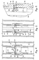
- FIGS 1 and 2 illustrate preferred oil delivery tubing integrity testing apparatus 10 in accordance with the present invention shown in use as part of an oil well 12.
- Oil well 12 is conventional in nature and includes casing 14, multi-segmented upper section 16 of oil delivery tubing (also known as a pipe string), multi-segmented lower section 18 and oil pump 20.
- preferred apparatus 10 includes rupture disc 22 and holder 24.
- Disc 22 is preferably composed of nickel 200 and includes bulge portion 26 and surrounding flange 28. Bulge portion 26 presents a concavo-convex configuration with score line 30 defined on the convex side thereof.
- Score line 30 generally defines a circular shape except for a gap therein defining hinge area 32.
- Score line 30 circumscribes rupture segment 34 and is precisely scored so that disc 22 will rupture, that is, separate at score line 30, at a burst pressure of about 2000 psi applied to the concave side thereof. When this occurs, segment 34 rotates about hinge area 32 as illustrated in Figs. 5 and 6.
- rupture disc 22 will not burst at a test pressure of about 500 psi which is below the burst pressure of about 2000 psi.
- Rupture disc 22 also includes mounting ring 36, rectangular in cross section, and welded to flange 28 on the convex side of disc 22.
- Ring 36 presents about the same internal and external diameters as rupture disc 22, and the internal diameters of these two components are the same as the internal diameter of the preferred oil delivery tubing. Ring 36 ensures secure mounting of disc 22 within holder 24.
- Holder 24 includes upper member 38 and lower member 40.
- upper member 38 presents a generally tubular configuration and includes externally threaded coupling section 42 sized for threadably coupling with the internal threads of an adjacent length or segment 44 of oil delivery tubing.
- Upper member 38 further includes tubular, rupture disc mounting section 46 integral with coupling section 42 but presenting a greater inside diameter and a greater outside diameter.
- Mounting section 46 is internally threaded for threadably coupling with the external threads of lower member 40.
- the transition between coupling section 42 and mounting section 46 presents shoulder 48 which engages and supports rupture disc flange 28.
- Lower member 40 integrally includes upper portion 50 and lower portion 52.
- Upper portion 50 is externally threaded for threadably coupling with coupling section 42 of upper member 38 and presents end face 54. Also, upper portion 50 presents the same internal and external diameters as rupture disc flange 28 and mounting ring 36. With this configuration, end face 54 engages mounting ring 36 and compresses ring 36 and rupture disc flange 28 against shoulder 48. This securely mounts rupture disc 22 within holder 24.
- Lower portion 52 is externally threaded for threadably coupling with the internal threads of adjacent oil delivery segment 56.
- lower section 18 may include multiple segments of oil delivery tubing and as conventional, may include other components such as separators and the like.
- Apparatus 10 is then connected to the upper end of lower section 18. Specifically, this is accomplished by threadably coupling lower portion 52 of holder 24 with the upper end of tube segment 56.
- tubing segment 44 is threadably coupled with upper member 38 of holder 24 and successive tubing segments coupled in sequence to form upper section 16.
- upper section 16 is tested for integrity by filling with water under pressure to check for leaks.
- an hydraulic pump pressurizes the assembled segments of upper section 16 with water at a test pressure of about 500 psi.
- Rupture disc 22 seals the lower end of upper section 16 during the test. This procedure is repeated after each addition of ten segments of tubing until oil pump 20 is at the desired depth. If a leak is detected during any of the integrity tests, at most ten lengths of tubing will have to be removed and reassembled in order to correct the leak. With the integrity test of the present invention, the integrity of upper section 16 is established thereby assuring pumping efficiency and insuring against the expense of removing and reassembling the pipe string.
- upper section 16 When oil pump 20 is at the desired depth, upper section 16 is then pressurized with a burst pressure of about 2000 psi. That is, the hydraulic pressure in upper section 16 is increased until rupture disc 22 bursts at about 2000 psi. When this occurs, rupture segment 34 separates at score line 30 and rotates about hinge area 32 as represented in Fig. 5. The force of the burst is sufficient to cause rupture segment 34 to conform substantially to the interior surface of upper portion 50 of holder 24. This completely opens passage 58 through holder 24 for unrestricted fluid flow.
- push-pull rod 60 With passage 58 open, push-pull rod 60 can be inserted through the pipe string and through holder 24 and connected to oil pump 20. Conventional operation of oil well 12 can then occur.
- rupture disc 22 can be composed of a wide variety of materials known as being suitable for rupture discs.
- burst pressure of rupture disc can be specified as needed for particular applications.
- other configurations of the holder can also be developed suitable for particular applications.
Landscapes
- Geology (AREA)
- Physics & Mathematics (AREA)
- Life Sciences & Earth Sciences (AREA)
- Engineering & Computer Science (AREA)
- Mining & Mineral Resources (AREA)
- Environmental & Geological Engineering (AREA)
- Geophysics (AREA)
- Fluid Mechanics (AREA)
- Geochemistry & Mineralogy (AREA)
- General Life Sciences & Earth Sciences (AREA)
- Examining Or Testing Airtightness (AREA)
- Investigating Strength Of Materials By Application Of Mechanical Stress (AREA)
- Sampling And Sample Adjustment (AREA)
- Earth Drilling (AREA)
Claims (12)
- Vorrichtung (10) zum Prüfen der Vollständigkeit einer Öl-förderrohrleitung (16) in einer Ölbohrlochauskleidung (14) und welche einen rohrförmigen Halter (24) umfasst, der mit einem Durchlass versehen ist und der gegenüberliegende Enden (42, 52) hat, wobei eine Ende (42) des Halters so gestaltet ist, dass es an ein Ende eines Abschnitts eines Öl-förderrohrs anschließbar ist, wobei die Vorrichtung aufweist:eine Berstscheibe (22) in dem Halter (24), die normalerweise den Durchlass verschließt, wobei die Scheibe unter Druck geöffnet werden kann, um eine im Wesentlichen ungehinderte Strömung der Flüssigkeit an der Scheibe (22) vorbei durch die Öffnung zu gestatten,
wobei die Scheibe (22) eine kreisförmige Metallmembran aufweist, die einen Umfangsflanschabschnitt (28) und einen zentralen gewölbten Abschnitt (26) hat, der von einer konvexen Fläche und von einer konkaven Fläche an gegenüberliegenden Seiten des einen Abschnitts des Ölförderrohrs gebildet ist, wobei die Scheibe in dem Halter (24) an einer Stelle angeordnet und mit der konkaven Fläche dem Ende des rohrförmigen Abschnitts zugewendet ist, an dem der Halter angebracht ist,
wobei die Scheibe (22) mit unzusammenhängenden bogenförmigen Bruchlinien (30) im zentralen gewölbten Abschnitt (26) davon versehen ist, wobei die gegenüberliegenden Enden der Bruchlinien im Abstand zueinander liegen und einen Gelenkbereich (32) dazwischen bilden,
wobei die metallische Berstscheibe (22) einem hydraulischen Druck von einem ersten Prüfwert standhalten kann und so gestaltet ist, dass sie bricht und sich öffnet, wenn ein zweiter Berstdruck an die Scheibe angelegt wird, der wesentlich höher als der Prüfdruck ist, sodass sich beim Bersten der Scheibe (22) der zentrale gewölbte Abschnitt (26) öffnet und um den Gelenkbereich (32) biegt, ohne sich von dem Flanschabschnitt (28) der Scheibe (22) zu lösen, um eine im Wesentlichen freie Strömung von Öl durch die Öffnung des Halters (26) zu gestatten. - Vorrichtung nach Anspruch 1, wobei die Bruchlinie (30) in der konkaven Fläche des gewölbten Abschnitts (26) ist.
- Vorrichtung nach Anspruch 1, wobei die Bruchlinie (30) in naher Beziehung zu dem Umfangsflanschabschnitt (28) der Scheibe (22) liegt.
- Vorrichtung nach Anspruch 1, wobei der Halter (26) einen rohrförmigen Einlass (38) und einen rohrförmigen Auslass (40) aufweist, der lösbar an den Einlass (38) angeschlossen ist, wobei der rohrförmige Einlass (38) und der rohrförmige Auslass (40) zusammenwirken, um den Durchlass durch den Halter (24) zu bilden, wobei die Berstscheibe (22) zwischen dem Einlass (38) und dem Auslass (40) des Halters angeordnet ist und dabei den Durchlass durch den Halter überspannt und verschließt.
- Vorrichtung nach Anspruch 4, wobei der Einlass (38) und der Auslass (40) innere Zylinderflächen haben, die zusammenwirken, um den Durchlass durch den Halter (24) zu bilden, wobei der Durchmesser des Durchlasses, der von der inneren Zylinderfläche des Auslasses (40) gebildet ist, größer als der Durchmesser des Durchlasses ist, der von der inneren Zylinderfläche des Einlasses (38) gebildet wird.
- Vorrichtung nach Anspruch 5, wobei die inneren Zylinderflächen des Einlasses (38) und des Auslasses (40) zusammen einen Durchlass bilden, der einen Durchmesser hat, der etwa gleich wie der Innendurchmesser des Ölförderrohrabschnitts (16) ist.
- Verfahren zum Prüfen der Integrität eines mehrteiligen Ölförderrohrs in einer Ölbohrlochauskleidung, mit den Schritten:Vorsehen eines rohrförmigen Halters mit einem durchgehenden Durchlass, wobei der Halter (24) eine Berstscheibe (22) in Form einer kreisförmigen Metallmembran hat und mit einem Umfangsflanschabschnitt (28) und einem zentralen gewölbten Abschnitt (26) versehen ist, der von einer konvexen Fläche und einer konkaven Fläche gebildet wird, wobei die Scheibe in dem Halter (24) so angeordnet ist, dass deren zentraler gewölbter Abschnitt (26) den Durchlass normalerweise verschließt, wobei der gewölbte Abschnitt (26) unter Druck geöffnet werden kann, ohne dass der gewölbte Abschnitt von dem Flanschabschnitt abgelöst wird, wobei die Berstscheibe (22) ferner einem Hydraulikdruck von einem ersten Prüfwert standhalten kann und so konstruiert ist, dass sie bricht und sich öffnet, wenn ein zweiter Berstdruck wesentlich größer als der an die Scheibe angelegte Prüfdruck ist;Anbringen des rohrförmigen Halters (24) mit der normalerweise geschlossenen Scheibe (22) darin an dem Ende eines mehrteiligen Abschnitts (18) von Ölförderrohr (16), das in einen Ölbohrloch (12) abgesenkt werden soll;Absenken des mehrteiligen Abschnitts (18) des Ölförderrohrs (16) mit dem daran befindlichen Halter (24) in die Auskleidung (14) des Ölbohrlochs (12), wobei der Halter (24) an dem unteren Ende des Abschnitts (18) des Ölförderrohrs (16) angeordnet ist;Unterbrechen des Absenkens des mehrteiligen Abschnitts (18) des Ölförderrohrs (16) mit dem daran befindlichen Halter (24), wenn der mehrteilige Abschnitt (18) des Ölförderrohrs (16) in der Auskleidung (12) ein vorgegebenes Maß abgesenkt worden ist;Einleiten von hinreichend viel Flüssigkeit in den mehrteiligen Abschnitt (18) des Ölförderrohrs (16) um zu bewirken, dass sich der Abschnitt mit Flüssigkeit zumindest bis zur Höhe des Anschlusses von benachbarten Rohrabschnitten füllt, die auf Flüssigkeitsleckagen geprüft werden sollen,
wobei die Berstscheibe (22) dem Druck der in den mehrteiligen Abschnitt (18) des Ölförderrohrs (16) eingeleiteten Flüssigkeit standhalten kann, um Information darüber zu liefern, ob der mehrteilige Abschnitt (18) des Ölförderrohrs (16) im Wesentlichen leckdicht ist;
und danach Anlegen von einem hinreichend großen Flüssigkeitsdruck an die Berstscheibe (28) um die Scheibe aufzubrechen, ohne den gewölbten Abschnitt (26) von dem Umfangsabschnitt (28) abzutrennen, um eine im Wesentlichen freie Strömung von Flüssigkeit an der Scheibe (22) vorbei über die Querschnittsfläche des Durchlasses zuzulassen, wenn es gewünscht wird, den Durchlass zu öffnen, um Ö1 von dem Ölbohrloch durch die Verrohrung zu fördern. - Verfahren nach Anspruch 7, mit den Schritten des Anbringens von einem weiteren mehrteiligen Abschnitt (18) von Ölförderrohr (16) an dem mehrteiligen Abschnitt des Ölförderrohrs mit dem daran angebrachten Halter, ferner Absenken des mehrteiligen Ölförderrohrs in die Auskleidung (14) des Ölbohrlochs (12), Einleiten von zusätzlicher Flüssigkeit in das mehrteilige Ölförderrohr (18) damit die zusammengefassten mehrteiligen Ölförderrohrabschnitte mit einer Flüssigkeit zumindest bis zur Höhe des Anschlusses von benachbarten Rohrabschnitten gefüllt werden kann, die auf Flüssigkeitslecks geprüft werden sollen, wobei die Berstscheibe (22) dem Druck der zusätzlichen Flüssigkeit standhalten kann, die in die mehrteiligen Abschnitte (18) des Ölförderrohrs (16) eingespeist werden, um zusätzliche Information zu liefern, ob die mehrteiligen Abschnitte (18) des Ölförderrohrs (16) im Wesentlichen leckdicht sind.
- Verfahren nach Anspruch 8, wobei die Schritte des Hinzufügens von mehrteiligen Ölförderrohrabschnitten (18) zur Länge des Förderrohrs (16) und das Hinzufügen von weiteren Mengen von Flüssigkeit zum Prüfen der Integrität von Verbindungen von benachbarten Rohrabschnitten (18) fortgesetzt wird, bis der Halter (24) mit der Berstscheibe (22) darin sich auf einer Höhe befindet, auf der Ö1 von dem Ölbohrloch (12) durch das Förderrohr (16) gepumpt werden soll.
- Verfahren nach Anspruch 9, mit dem Schritt des Anlegens von Zwischenniveaudruck an die Flüssigkeit, die sich in den mehrteiligen Ölförderrohrabschnitten (18) befindet, bei einem Druckniveau, das unter dem Berstdruck der Berstscheibe (22) liegt, jedoch über dem Druck, der auf die Berstscheibe durch das Gewicht der Flüssigkeit in den mehrteiligen Ölförderrohrabschnitten (18) wirkt, um eine Abschlußprüfung der Integrität der Verbindungen von Abschnitten der Ölförderrohrabschnitte (18) zu ergeben.
- Verfahren nach Anspruch 10, mit dem Schritt des Anlegens eines Zwischenflüssigkeitsdruck von mindestens etwa 3,45 MPa (500 psi) an die Flüssigkeit in den mehrteiligen Ölförderrohrabschnitten (18).
- Verfahren nach Anspruch 10, mit dem Schritt des Anlegens eines Endflüssigkeitsdrucks von mindestens etwa 13,8 MPa (2000 psi) an die Flüssigkeit in den mehrteiligen Ölförderrohrabschnitten (18) und der zum Aufbrechen der Berstscheibe (22) ausreicht.
Applications Claiming Priority (5)
| Application Number | Priority Date | Filing Date | Title |
|---|---|---|---|
| US5102797P | 1997-06-27 | 1997-06-27 | |
| US51027P | 1997-06-27 | ||
| US08/957,216 US5996696A (en) | 1997-06-27 | 1997-10-24 | Method and apparatus for testing the integrity of oil delivery tubing within an oil well casing |
| US957216 | 1997-10-24 | ||
| PCT/US1998/009610 WO1999000578A1 (en) | 1997-06-27 | 1998-05-13 | Apparatus and method for determining integrity of oil well tubing |
Publications (3)
| Publication Number | Publication Date |
|---|---|
| EP1009907A1 EP1009907A1 (de) | 2000-06-21 |
| EP1009907A4 EP1009907A4 (de) | 2000-08-23 |
| EP1009907B1 true EP1009907B1 (de) | 2006-02-15 |
Family
ID=26728975
Family Applications (1)
| Application Number | Title | Priority Date | Filing Date |
|---|---|---|---|
| EP98921122A Expired - Lifetime EP1009907B1 (de) | 1997-06-27 | 1998-05-13 | Vorrichtung und verfahren zur bestimmung der integrität von bohrlochrohren |
Country Status (9)
| Country | Link |
|---|---|
| US (1) | US5996696A (de) |
| EP (1) | EP1009907B1 (de) |
| JP (1) | JP2002511909A (de) |
| CN (1) | CN1087806C (de) |
| AT (1) | ATE317940T1 (de) |
| BR (1) | BR9810344A (de) |
| DE (1) | DE69833484T2 (de) |
| HK (1) | HK1028989A1 (de) |
| WO (1) | WO1999000578A1 (de) |
Cited By (4)
| Publication number | Priority date | Publication date | Assignee | Title |
|---|---|---|---|---|
| US11199071B2 (en) * | 2017-11-20 | 2021-12-14 | Halliburton Energy Services, Inc. | Full bore buoyancy assisted casing system |
| US11416650B2 (en) | 2017-06-16 | 2022-08-16 | Landmark Graphics Corporation | Optimized visualization of loads and resistances for wellbore tubular design |
| US11499395B2 (en) | 2019-08-26 | 2022-11-15 | Halliburton Energy Services, Inc. | Flapper disk for buoyancy assisted casing equipment |
| US11982158B2 (en) | 2020-03-24 | 2024-05-14 | Landmark Graphics Corporation | Systems and methods for borehole tubular design |
Families Citing this family (17)
| Publication number | Priority date | Publication date | Assignee | Title |
|---|---|---|---|---|
| US6575243B2 (en) | 2001-04-16 | 2003-06-10 | Schlumberger Technology Corporation | Zonal isolation tool with same trip pressure test |
| WO2003052239A1 (en) * | 2001-12-17 | 2003-06-26 | Fike Corporation | Hinged rupture disc with circular score line |
| US6672389B1 (en) * | 2002-07-31 | 2004-01-06 | Fike Corporation | Bulged single-hinged scored rupture having a non-circular varying depth score line |
| US6966368B2 (en) * | 2003-06-24 | 2005-11-22 | Baker Hughes Incorporated | Plug and expel flow control device |
| US7513311B2 (en) * | 2006-04-28 | 2009-04-07 | Weatherford/Lamb, Inc. | Temporary well zone isolation |
| CN100422503C (zh) * | 2006-10-31 | 2008-10-01 | 刘文西 | 膨胀管组合补井装置 |
| US7950409B2 (en) * | 2007-01-30 | 2011-05-31 | Fike Corporation | Rupture disc assembly that withstands much higher back pressures than actuation pressure |
| US7533727B2 (en) | 2007-05-04 | 2009-05-19 | Fike Corporation | Oil well completion tool having severable tubing string barrier disc |
| JP5346332B2 (ja) * | 2007-09-20 | 2013-11-20 | ファイク・コーポレーション | 分断可能なチュービングストリング遮断ディスクを有する油井仕上げツール |
| US7806189B2 (en) | 2007-12-03 | 2010-10-05 | W. Lynn Frazier | Downhole valve assembly |
| US7661480B2 (en) * | 2008-04-02 | 2010-02-16 | Saudi Arabian Oil Company | Method for hydraulic rupturing of downhole glass disc |
| US8066074B2 (en) * | 2008-11-18 | 2011-11-29 | Chevron U.S.A. Inc. | Systems and methods for mitigating annular pressure buildup in an oil or gas well |
| AU2011366243B2 (en) * | 2011-04-19 | 2015-04-02 | Landmark Graphics Corporation | Determining well integrity |
| US9593542B2 (en) | 2013-02-05 | 2017-03-14 | Ncs Multistage Inc. | Casing float tool |
| US11149522B2 (en) | 2020-02-20 | 2021-10-19 | Nine Downhole Technologies, Llc | Plugging device |
| NO346282B1 (en) | 2020-05-04 | 2022-05-23 | Nine Downhole Norway As | Shearable sleeve |
| CN113532749B (zh) * | 2021-07-13 | 2023-09-08 | 西南石油大学 | 一种外置式油套管螺纹连接气密性检测封隔器 |
Family Cites Families (36)
| Publication number | Priority date | Publication date | Assignee | Title |
|---|---|---|---|---|
| US244042A (en) * | 1881-07-12 | Ohiliok m | ||
| US1569293A (en) * | 1923-01-23 | 1926-01-12 | Carlton E Miller | Device for introducing cement in wells |
| US2043225A (en) * | 1935-07-05 | 1936-06-09 | Arthur L Armentrout | Method and apparatus for testing the productivity of the formation in wells |
| US2461727A (en) * | 1945-01-20 | 1949-02-15 | Robert I Gardner | Means and method for detecting leaks in drill stems |
| US2855049A (en) * | 1954-11-12 | 1958-10-07 | Zandmer Solis Myron | Duct-forming devices |
| US3062292A (en) * | 1954-12-17 | 1962-11-06 | Lowrey | Well packer |
| US3091293A (en) * | 1959-07-10 | 1963-05-28 | Dresser Ind | Plugging device for wells |
| US3095040A (en) * | 1961-06-30 | 1963-06-25 | Bramlett Oil Field Service Inc | Access valve for completing oil wells |
| US3115186A (en) * | 1961-09-18 | 1963-12-24 | Albert K Kline | Bridge plug |
| US3166124A (en) * | 1962-05-24 | 1965-01-19 | Shell Oil Co | Wellhead closure plug |
| US3211229A (en) * | 1962-11-21 | 1965-10-12 | Bramlett Oil Field Service Inc | Oil well completion tool |
| US3599713A (en) * | 1969-09-08 | 1971-08-17 | Fishing Tools Inc | Method and apparatus for controlling the filling of drill pipe or the like with mud during lowering thereof |
| US3662834A (en) * | 1970-06-03 | 1972-05-16 | Schlumberger Technology Corp | Methods and apparatus for completing production wells |
| US3980134A (en) * | 1973-12-26 | 1976-09-14 | Otis Engineering Corporation | Well packer with frangible closure |
| US4040485A (en) * | 1974-10-23 | 1977-08-09 | Vann Tool Company, Inc. | Method of simultaneously setting a packer device and actuating a vent assembly |
| US4031960A (en) * | 1976-02-25 | 1977-06-28 | Teledyne, Inc. | Circulating valve |
| GB1565004A (en) * | 1977-04-18 | 1980-04-16 | Weatherford Dmc | Chemical cutting appratus and method for use in wells |
| US4237980A (en) * | 1979-03-15 | 1980-12-09 | R & C Machine Devon Ltd. | Check valve for fluid-producing wells |
| US4281715A (en) * | 1979-05-16 | 1981-08-04 | Halliburton Company | Bypass valve |
| US4314608A (en) * | 1980-06-12 | 1982-02-09 | Tri-State Oil Tool Industries, Inc. | Method and apparatus for well treating |
| US4374543A (en) * | 1980-08-19 | 1983-02-22 | Tri-State Oil Tool Industries, Inc. | Apparatus for well treating |
| US4609005A (en) * | 1985-07-19 | 1986-09-02 | Schlumberger Technology Corporation | Tubing isolation disc valve |
| US4691775A (en) * | 1986-03-25 | 1987-09-08 | Dresser Industries, Inc. | Isolation valve with frangible flapper element |
| US4694903A (en) * | 1986-06-20 | 1987-09-22 | Halliburton Company | Flapper type annulus pressure responsive tubing tester valve |
| US4784226A (en) * | 1987-05-22 | 1988-11-15 | Arrow Oil Tools, Inc. | Drillable bridge plug |
| US4911242A (en) * | 1988-04-06 | 1990-03-27 | Schlumberger Technology Corporation | Pressure-controlled well tester operated by one or more selected actuating pressures |
| US4907655A (en) * | 1988-04-06 | 1990-03-13 | Schlumberger Technology Corporation | Pressure-controlled well tester operated by one or more selected actuating pressures |
| US4846272A (en) * | 1988-08-18 | 1989-07-11 | Eastern Oil Tolls Pte, Ltd. | Downhole shuttle valve for wells |
| US5044444A (en) * | 1989-04-28 | 1991-09-03 | Baker Hughes Incorporated | Method and apparatus for chemical treatment of subterranean well bores |
| US5193621A (en) * | 1991-04-30 | 1993-03-16 | Halliburton Company | Bypass valve |
| US5318126A (en) * | 1992-03-26 | 1994-06-07 | Schlumberger Technology Corporation | Explosively opened production valve including a frangible breakup element operated by tubing pressure or rathole pressure or both |
| US5271465A (en) * | 1992-04-27 | 1993-12-21 | Atlantic Richfield Company | Over-pressured well fracturing method |
| US5341883A (en) * | 1993-01-14 | 1994-08-30 | Halliburton Company | Pressure test and bypass valve with rupture disc |
| US5511617A (en) * | 1994-08-04 | 1996-04-30 | Snider; Philip M. | Apparatus and method for temporarily plugging a tubular |
| GB9515362D0 (en) * | 1995-07-26 | 1995-09-20 | Petroline Wireline Services | Improved check valve |
| US5934308A (en) * | 1995-10-24 | 1999-08-10 | Bs&B Safety Systems, Inc. | Rupture disk apparatus and methods |
-
1997
- 1997-10-24 US US08/957,216 patent/US5996696A/en not_active Expired - Lifetime
-
1998
- 1998-05-13 JP JP50552999A patent/JP2002511909A/ja active Pending
- 1998-05-13 CN CN98806392A patent/CN1087806C/zh not_active Expired - Fee Related
- 1998-05-13 AT AT98921122T patent/ATE317940T1/de not_active IP Right Cessation
- 1998-05-13 WO PCT/US1998/009610 patent/WO1999000578A1/en active IP Right Grant
- 1998-05-13 DE DE69833484T patent/DE69833484T2/de not_active Expired - Fee Related
- 1998-05-13 BR BR9810344-0A patent/BR9810344A/pt not_active IP Right Cessation
- 1998-05-13 EP EP98921122A patent/EP1009907B1/de not_active Expired - Lifetime
-
2000
- 2000-12-12 HK HK00107979A patent/HK1028989A1/xx not_active IP Right Cessation
Cited By (4)
| Publication number | Priority date | Publication date | Assignee | Title |
|---|---|---|---|---|
| US11416650B2 (en) | 2017-06-16 | 2022-08-16 | Landmark Graphics Corporation | Optimized visualization of loads and resistances for wellbore tubular design |
| US11199071B2 (en) * | 2017-11-20 | 2021-12-14 | Halliburton Energy Services, Inc. | Full bore buoyancy assisted casing system |
| US11499395B2 (en) | 2019-08-26 | 2022-11-15 | Halliburton Energy Services, Inc. | Flapper disk for buoyancy assisted casing equipment |
| US11982158B2 (en) | 2020-03-24 | 2024-05-14 | Landmark Graphics Corporation | Systems and methods for borehole tubular design |
Also Published As
| Publication number | Publication date |
|---|---|
| ATE317940T1 (de) | 2006-03-15 |
| HK1028989A1 (en) | 2001-03-16 |
| CN1087806C (zh) | 2002-07-17 |
| US5996696A (en) | 1999-12-07 |
| DE69833484D1 (de) | 2006-04-20 |
| WO1999000578A1 (en) | 1999-01-07 |
| CN1268993A (zh) | 2000-10-04 |
| JP2002511909A (ja) | 2002-04-16 |
| AU723798B2 (en) | 2000-09-07 |
| EP1009907A1 (de) | 2000-06-21 |
| AU7379998A (en) | 1999-01-19 |
| BR9810344A (pt) | 2000-08-29 |
| EP1009907A4 (de) | 2000-08-23 |
| DE69833484T2 (de) | 2006-09-14 |
Similar Documents
| Publication | Publication Date | Title |
|---|---|---|
| EP1009907B1 (de) | Vorrichtung und verfahren zur bestimmung der integrität von bohrlochrohren | |
| JP4124574B2 (ja) | 下げ穴ダンプ弁 | |
| AU610549B2 (en) | Pipe connector and method of applying same | |
| US6672389B1 (en) | Bulged single-hinged scored rupture having a non-circular varying depth score line | |
| US7267178B2 (en) | Fluid system component with sacrificial element | |
| US9217308B2 (en) | Active external casing packer (ECP) for frac operations in oil and gas wells | |
| US5267469A (en) | Method and apparatus for testing the physical integrity of production tubing and production casing in gas-lift wells systems | |
| MX2008002556A (es) | Ensamble de sello de guia interior para un sistema impedidor de estallido tipo ariete. | |
| US8833448B2 (en) | Fluid system component with sacrificial element | |
| US7086473B1 (en) | Submersible pumping system with sealing device | |
| AU723798C (en) | Apparatus and method for determining integrity of oil well tubing | |
| US20020108750A1 (en) | Full opening bulged forward acting rupture disc having variable depth score line | |
| WO2003052239A1 (en) | Hinged rupture disc with circular score line | |
| CA2179952C (en) | Adapter for oil well tubings | |
| US20050252661A1 (en) | Casing degasser tool | |
| US11781694B2 (en) | Clamped saddle for directional hot-tapping tubulars | |
| CA2735753C (en) | Fluid system component with sacrificial element | |
| RU2783578C1 (ru) | Клапан опрессовочный мембранный, скважинная компоновка и способ эксплуатации клапана | |
| GB2267352A (en) | Pressure testing gas-lift wells | |
| RU2737747C2 (ru) | Двухпакерная компоновка для перекрытия негерметичных участков эксплуатационных колонн нефтяных и газовых скважин | |
| SU1684466A1 (ru) | Способ опрессовки колонны труб в скважине | |
| CA1221908A (en) | Method of preparing an inflatable packer for running | |
| RU2214503C1 (ru) | Устройство для цементирования дополнительной обсадной колонны |
Legal Events
| Date | Code | Title | Description |
|---|---|---|---|
| PUAI | Public reference made under article 153(3) epc to a published international application that has entered the european phase |
Free format text: ORIGINAL CODE: 0009012 |
|
| 17P | Request for examination filed |
Effective date: 20000104 |
|
| AK | Designated contracting states |
Kind code of ref document: A1 Designated state(s): AT BE CH CY DE DK ES FI FR GB GR IE IT LI LU MC NL PT SE |
|
| A4 | Supplementary search report drawn up and despatched |
Effective date: 20000712 |
|
| AK | Designated contracting states |
Kind code of ref document: A4 Designated state(s): AT BE CH CY DE DK ES FI FR GB GR IE IT LI LU MC NL PT SE |
|
| RIC1 | Information provided on ipc code assigned before grant |
Free format text: 7E 21B 47/10 A, 7E 21B 34/06 B |
|
| 17Q | First examination report despatched |
Effective date: 20040415 |
|
| GRAP | Despatch of communication of intention to grant a patent |
Free format text: ORIGINAL CODE: EPIDOSNIGR1 |
|
| GRAS | Grant fee paid |
Free format text: ORIGINAL CODE: EPIDOSNIGR3 |
|
| GRAA | (expected) grant |
Free format text: ORIGINAL CODE: 0009210 |
|
| AK | Designated contracting states |
Kind code of ref document: B1 Designated state(s): AT BE CH CY DE DK ES FI FR GB GR IE IT LI LU MC NL PT SE |
|
| PG25 | Lapsed in a contracting state [announced via postgrant information from national office to epo] |
Ref country code: NL Free format text: LAPSE BECAUSE OF FAILURE TO SUBMIT A TRANSLATION OF THE DESCRIPTION OR TO PAY THE FEE WITHIN THE PRESCRIBED TIME-LIMIT Effective date: 20060215 Ref country code: LI Free format text: LAPSE BECAUSE OF FAILURE TO SUBMIT A TRANSLATION OF THE DESCRIPTION OR TO PAY THE FEE WITHIN THE PRESCRIBED TIME-LIMIT Effective date: 20060215 Ref country code: FI Free format text: LAPSE BECAUSE OF FAILURE TO SUBMIT A TRANSLATION OF THE DESCRIPTION OR TO PAY THE FEE WITHIN THE PRESCRIBED TIME-LIMIT Effective date: 20060215 Ref country code: CH Free format text: LAPSE BECAUSE OF FAILURE TO SUBMIT A TRANSLATION OF THE DESCRIPTION OR TO PAY THE FEE WITHIN THE PRESCRIBED TIME-LIMIT Effective date: 20060215 Ref country code: AT Free format text: LAPSE BECAUSE OF FAILURE TO SUBMIT A TRANSLATION OF THE DESCRIPTION OR TO PAY THE FEE WITHIN THE PRESCRIBED TIME-LIMIT Effective date: 20060215 |
|
| REG | Reference to a national code |
Ref country code: GB Ref legal event code: FG4D Ref country code: CH Ref legal event code: EP |
|
| REG | Reference to a national code |
Ref country code: IE Ref legal event code: FG4D |
|
| REF | Corresponds to: |
Ref document number: 69833484 Country of ref document: DE Date of ref document: 20060420 Kind code of ref document: P |
|
| REG | Reference to a national code |
Ref country code: HK Ref legal event code: GR Ref document number: 1028989 Country of ref document: HK |
|
| PGFP | Annual fee paid to national office [announced via postgrant information from national office to epo] |
Ref country code: DE Payment date: 20060511 Year of fee payment: 9 |
|
| PG25 | Lapsed in a contracting state [announced via postgrant information from national office to epo] |
Ref country code: SE Free format text: LAPSE BECAUSE OF FAILURE TO SUBMIT A TRANSLATION OF THE DESCRIPTION OR TO PAY THE FEE WITHIN THE PRESCRIBED TIME-LIMIT Effective date: 20060515 Ref country code: DK Free format text: LAPSE BECAUSE OF FAILURE TO SUBMIT A TRANSLATION OF THE DESCRIPTION OR TO PAY THE FEE WITHIN THE PRESCRIBED TIME-LIMIT Effective date: 20060515 |
|
| PGFP | Annual fee paid to national office [announced via postgrant information from national office to epo] |
Ref country code: FR Payment date: 20060515 Year of fee payment: 9 |
|
| PG25 | Lapsed in a contracting state [announced via postgrant information from national office to epo] |
Ref country code: ES Free format text: LAPSE BECAUSE OF FAILURE TO SUBMIT A TRANSLATION OF THE DESCRIPTION OR TO PAY THE FEE WITHIN THE PRESCRIBED TIME-LIMIT Effective date: 20060526 |
|
| PG25 | Lapsed in a contracting state [announced via postgrant information from national office to epo] |
Ref country code: MC Free format text: LAPSE BECAUSE OF NON-PAYMENT OF DUE FEES Effective date: 20060531 |
|
| PGFP | Annual fee paid to national office [announced via postgrant information from national office to epo] |
Ref country code: IT Payment date: 20060531 Year of fee payment: 9 |
|
| PGFP | Annual fee paid to national office [announced via postgrant information from national office to epo] |
Ref country code: BE Payment date: 20060712 Year of fee payment: 9 |
|
| PG25 | Lapsed in a contracting state [announced via postgrant information from national office to epo] |
Ref country code: PT Free format text: LAPSE BECAUSE OF FAILURE TO SUBMIT A TRANSLATION OF THE DESCRIPTION OR TO PAY THE FEE WITHIN THE PRESCRIBED TIME-LIMIT Effective date: 20060717 |
|
| NLV1 | Nl: lapsed or annulled due to failure to fulfill the requirements of art. 29p and 29m of the patents act | ||
| REG | Reference to a national code |
Ref country code: CH Ref legal event code: PL |
|
| ET | Fr: translation filed | ||
| PLBE | No opposition filed within time limit |
Free format text: ORIGINAL CODE: 0009261 |
|
| STAA | Information on the status of an ep patent application or granted ep patent |
Free format text: STATUS: NO OPPOSITION FILED WITHIN TIME LIMIT |
|
| 26N | No opposition filed |
Effective date: 20061116 |
|
| PGFP | Annual fee paid to national office [announced via postgrant information from national office to epo] |
Ref country code: IE Payment date: 20070514 Year of fee payment: 10 |
|
| PGFP | Annual fee paid to national office [announced via postgrant information from national office to epo] |
Ref country code: GB Payment date: 20070509 Year of fee payment: 10 |
|
| BERE | Be: lapsed |
Owner name: *FIKE CORP. Effective date: 20070531 |
|
| REG | Reference to a national code |
Ref country code: FR Ref legal event code: ST Effective date: 20080131 |
|
| PG25 | Lapsed in a contracting state [announced via postgrant information from national office to epo] |
Ref country code: BE Free format text: LAPSE BECAUSE OF NON-PAYMENT OF DUE FEES Effective date: 20070531 |
|
| PG25 | Lapsed in a contracting state [announced via postgrant information from national office to epo] |
Ref country code: GR Free format text: LAPSE BECAUSE OF FAILURE TO SUBMIT A TRANSLATION OF THE DESCRIPTION OR TO PAY THE FEE WITHIN THE PRESCRIBED TIME-LIMIT Effective date: 20060516 Ref country code: DE Free format text: LAPSE BECAUSE OF NON-PAYMENT OF DUE FEES Effective date: 20071201 |
|
| PG25 | Lapsed in a contracting state [announced via postgrant information from national office to epo] |
Ref country code: LU Free format text: LAPSE BECAUSE OF NON-PAYMENT OF DUE FEES Effective date: 20060513 Ref country code: FR Free format text: LAPSE BECAUSE OF NON-PAYMENT OF DUE FEES Effective date: 20070531 |
|
| PG25 | Lapsed in a contracting state [announced via postgrant information from national office to epo] |
Ref country code: CY Free format text: LAPSE BECAUSE OF FAILURE TO SUBMIT A TRANSLATION OF THE DESCRIPTION OR TO PAY THE FEE WITHIN THE PRESCRIBED TIME-LIMIT Effective date: 20060215 |
|
| GBPC | Gb: european patent ceased through non-payment of renewal fee |
Effective date: 20080513 |
|
| PG25 | Lapsed in a contracting state [announced via postgrant information from national office to epo] |
Ref country code: IE Free format text: LAPSE BECAUSE OF NON-PAYMENT OF DUE FEES Effective date: 20080513 |
|
| PG25 | Lapsed in a contracting state [announced via postgrant information from national office to epo] |
Ref country code: GB Free format text: LAPSE BECAUSE OF NON-PAYMENT OF DUE FEES Effective date: 20080513 |
|
| PG25 | Lapsed in a contracting state [announced via postgrant information from national office to epo] |
Ref country code: IT Free format text: LAPSE BECAUSE OF NON-PAYMENT OF DUE FEES Effective date: 20070513 |