EP1009554B1 - Vorrichtung zum schnellen abfördern von stäben und profilen auf ein küjlbett in walzanlagen - Google Patents
Vorrichtung zum schnellen abfördern von stäben und profilen auf ein küjlbett in walzanlagen Download PDFInfo
- Publication number
- EP1009554B1 EP1009554B1 EP98900989A EP98900989A EP1009554B1 EP 1009554 B1 EP1009554 B1 EP 1009554B1 EP 98900989 A EP98900989 A EP 98900989A EP 98900989 A EP98900989 A EP 98900989A EP 1009554 B1 EP1009554 B1 EP 1009554B1
- Authority
- EP
- European Patent Office
- Prior art keywords
- bar
- bars
- channel
- internal
- external
- Prior art date
- Legal status (The legal status is an assumption and is not a legal conclusion. Google has not performed a legal analysis and makes no representation as to the accuracy of the status listed.)
- Expired - Lifetime
Links
Images


Classifications
-
- B—PERFORMING OPERATIONS; TRANSPORTING
- B21—MECHANICAL METAL-WORKING WITHOUT ESSENTIALLY REMOVING MATERIAL; PUNCHING METAL
- B21B—ROLLING OF METAL
- B21B43/00—Cooling beds, whether stationary or moving; Means specially associated with cooling beds, e.g. for braking work or for transferring it to or from the bed
- B21B43/003—Transfer to bed
-
- B—PERFORMING OPERATIONS; TRANSPORTING
- B21—MECHANICAL METAL-WORKING WITHOUT ESSENTIALLY REMOVING MATERIAL; PUNCHING METAL
- B21B—ROLLING OF METAL
- B21B43/00—Cooling beds, whether stationary or moving; Means specially associated with cooling beds, e.g. for braking work or for transferring it to or from the bed
- B21B43/02—Cooling beds comprising rakes racks, walking beams or bars
-
- B—PERFORMING OPERATIONS; TRANSPORTING
- B21—MECHANICAL METAL-WORKING WITHOUT ESSENTIALLY REMOVING MATERIAL; PUNCHING METAL
- B21B—ROLLING OF METAL
- B21B43/00—Cooling beds, whether stationary or moving; Means specially associated with cooling beds, e.g. for braking work or for transferring it to or from the bed
- B21B43/08—Cooling beds comprising revolving drums or recycling chains or discs
Definitions
- This invention has for object a device for the high speed discharge of bars and sections on cooling bed in hot rolling mill plants.
- the speeds existing in the steel bars hot-rolling plants is of about 12 - 13 m/sec for systems with openable channel or with reciprocating movement and of about. 35 m/sec for rotating drum-channels.
- This invention is substantially intended for stock receiving and discharge devices with channels provided with openable means with reciprocating oscillating movement.
- the main cause is in the stand-off forced by the receiving of the rolling bars downstream of the "flying shear", that cuts the continuous rolled section or bar stock, into pieces deviating it by sending a bar on one side and a bar on the other in a known stock receiving device that receives the bar by two parallel adjacent channels.
- the channels are generally openable and closable and/or provided with other movement for discharging the bars received in turn on the underlying cooling bed.
- This solution is preferably intended for the production of small sections, which is penalised by roller ways and cursors, respect to bigger sections due to said speed limit.
- Purpose of the present invention is of increasing the production speed of the small sections (shaped like angles "L”, and T, U sections, square sections, hexagon sections, window sections, flat-shaped, and so on.) without however endangering their straightness, avoiding screwing not accepted by the market or by machines for the subsequent processing.
- a device for receiving bars and sections and discharging them on a underlying cooling bed involving a toothed plate, in rolling mill plants of the type which includes movable "U" shaped channels closable by covers, for the bars receiving, characterised in that it is structured by the following combined characteristics:
- the number of said channels is two, an internal one toward said toothed plate and an external one, and in which they lay coplanar, and the internal one extends downwards with an arm to act as a momentary stop of the advancement of the bars deposited upstream by said external channel in said transfer.
- said channels are offset in height and the internal one is at an higher level than the external one and in which the respective arms are of the oscillating type, hinged on the outside and such not to interfere one respect to the other in the respective movement.
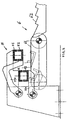
- Figure 1 is a schematic front cross sectional view on the vertical-plane of a first solution of the device for the receiving and discharging of bars according to the present invention.
- Figure 2 is a schematic view of the plant of Fig. 1 in the respective phases A),B),C),D)E), of its working.
- Fig. 3 is a view of a alternative solution as regards the solution of Fig.1.
- Fig.4 shows the phases of the solution of Fig.3.
- the underlying cooling bed (6) includes a transversal translator with endless chains or endless tape or rollers herein called endless transfer means (61), upstream of a known translating system with toothed plane called cooling plate or toothed plate (62) which notoriously works comb-like to move a bar from a seat (between two teeth) to the other.
- the upper placed device for the bars receiving and discharging (5) includes two parallel and adjacent channels arranged on horizontal-plane above the underlying bed 6.
- Each channel is made up of an upper part as cap (51) and lower part as a real "U" shaped channel (52), the lower part (52) is movable to open and discharge the bar received on the underlying bed.
- the bars are indicated by way of examples by 1,2,3,4 for locating them in logic succession of arrival, in order to understand the mechanism or receiving and discharging system.
- the invention therefore consists of two channels whose lower part, substantially "U” shaped (52), is vertically movable (or almost vertically).
- the two channels alternatively discharge the bars above the underlying transfer (61) that will carry it towards the plate (52), which will receive them by placing them one for each tooth (toothed seat).
- the internal channel placed toward the plate must also retain the bar discharged from the external channel in order to space it from the bar 2, 3 and allow the plate (62) to rotate (advance in rotational movement) avoiding charging the bar 1 on the same tooth occupied by the bar 2.
- the bar 1 is made free.
- the lifting / lowering control of the two channels may be of different type (520):
- the upper closure of the channels is supported by a longitudinal beam (50), fixed to ground by a series of columns.
- Figures 3 and 4 substantially show a variation in which the lower "U” shaped movable channels, are moved by oscillating arms (520).
- the transferring device may be of any type, at the most also a tilted plane.
Landscapes
- Engineering & Computer Science (AREA)
- Mechanical Engineering (AREA)
- Reciprocating Conveyors (AREA)
- Intermediate Stations On Conveyors (AREA)
- Sheets, Magazines, And Separation Thereof (AREA)
- Heat Treatments In General, Especially Conveying And Cooling (AREA)
- Pretreatment Of Seeds And Plants (AREA)
Claims (5)
- Vorrichtung zum Abladen von Stäben und Profilen (5) auf einem darunterliegenden Kühlbett (6) mit gezähnter Kühlplatte (62), in Walzwerken, mit beweglichen "U"-förmigen Kanälen (52) zur Aufnahme von Stäben (1,2,3,4 .....), durch Abdeckungen (51) verschließbar:wobei unterhalb besagter Vorrichtung (5) ein Zwischentransfermittel (61) vorhanden ist, das besagte Stäbe (1,2,3,4, , ....) von den beweglichen "U -förmigen Kanälen (52) aufnimmt und überführt und sie auf besagter angrenzenden gezähnten Kühlplatte (6) ablädt, worauf eine weitere Überführung (62) folgt; gekennzeichnet dadurch, dassbesagtes unteres Zwischentransfermittel ein endloses Transfermittel (61) ist;besagte "U" -förmige Kanäle (52) sich unter die Stütze- und Überführungsebene von besagten endlosen Transfermitteln (61) absenken können, um besagte Stäbe (1,2,3,4 .....) auf der Auflageebene von besagtem Transfer (61) abzulegen.
- Vorrichtung nach Anspruch 1, gekennzeichnet dadurch, dass die Anzahl der besagten Kanäle zwei ist, ein innerer (51-52) zu besagter gezähnter Platte (62) hin und ein äußerer (51-52), und wobei sie koplanar liegen und der innere mit einem Arm (520) nach unten ragt, um als Stopper für das momentane Vorrücken der Stäbe zu wirken, die vorher von besagtem äußeren Kanal in besagten Transfer (61) gelegt werden.
- Vorrichtung nach Anspruch 1, gekennzeichnet dadurch, dass besagte Kanäle in der Höhe versetzt sind und der innere höher liegt als der äußere, und wobei die betreffende Arme schwingen, in Eingriff auf der Außenseite, so dass sie einander nicht bei ihrer Bewegung stören.
- Methode zur Überführung von Stäben auf ein Kühlbett unter Benutzung einer Kanalvorrichtung zur Aufnahme von Stäben unter Vorrücken in Längsrichtung und zu ihrer Überführung auf besagtes Kühlbett durch eine Vorrichtung und Anlage nach Anspruch 1,2, gekennzeichnet dadurch, dass:ein erster Stab (1) in dem äußeren Kanal ankommt;ein zweiter Stab (2) im inneren Kanal ankommt;der äußere Kanal unter die Überführungs-Vorrücklinie abgesenkt wird, damit besagter erster Stab (1) vorrückt;der erste Stab (1) unter Vorhandensein von besagtem inneren Kanal durch besagte Überführung angehalten wird;besagter äußerer Kanal durch Anheben eingeschlossen wird, zur Aufnahme eines dritten Stabs (3), und besagter innerer Kanal abgesenkt wird, damit besagter zweiter Stab (2) von besagter Überführung vor besagtem ersten Stab (1) fortbewegt wird;besagter innerer Kanal in einer Position angehalten wird, so dass besagter erster Stab angehalten (1) wird und besagter zweiter Stab (2) sich in besagter gezähnter Platte um einen Zahn vorwärtsbewegt;besagter innerer Kanal weiter abgesenkt wird, um das Vorrücken von besagtem ersten Stab (1) zu besagter gezähnter Platte hin zu gestatten.
- Methode zur Überführung von Stäben auf ein Kühlbett unter Benutzung einer Kanalvorrichtung zur Aufnahme von Stäben unter Vorrücken in Längsrichtung und zu ihrer Überführung auf besagtes Kühlbett durch eine Vorrichtung und Anlage nach Anspruch 1,2, gekennzeichnet dadurch, dass:ein erster Stab (1) in dem äußeren Kanal ankommt;der äußere Kanal unter die Überführungs-Vorrücklinie abgesenkt wird, damit besagter erster Stab (1) bis zu besagter Kühlplatte vorrückt, während gleichzeitig besagter zweiter Stab (2) im inneren Kanal ankommt, der besagtes Vorrücken nicht stört;besagter äußerer Kanal durch Anheben eingeschlossen wird, zur Aufnahme eines dritten Stabs (3), und besagter innerer Kanal eingeschlossen wird, zur Aufnahme des besagten vierten Stabs (4) und zum Freimachen des Wegs für die Abladung des dritten Stabs (3) wie i n der vorherigen Phase.
Applications Claiming Priority (4)
| Application Number | Priority Date | Filing Date | Title |
|---|---|---|---|
| ITUD970000 | 1997-01-22 | ||
| IT97UD000009A IT1290711B1 (it) | 1997-01-22 | 1997-01-22 | Dispositivo per lo scarico ad alta velocita' in placca di barre e profili in impianti di laminazione |
| ITUD970009 | 1997-01-22 | ||
| PCT/IT1998/000004 WO1998032550A1 (en) | 1997-01-22 | 1998-01-16 | Device for high speed discharge of bars and sections on cooling bed in hot rolling mill plants |
Publications (2)
| Publication Number | Publication Date |
|---|---|
| EP1009554A1 EP1009554A1 (de) | 2000-06-21 |
| EP1009554B1 true EP1009554B1 (de) | 2002-12-04 |
Family
ID=11422272
Family Applications (1)
| Application Number | Title | Priority Date | Filing Date |
|---|---|---|---|
| EP98900989A Expired - Lifetime EP1009554B1 (de) | 1997-01-22 | 1998-01-16 | Vorrichtung zum schnellen abfördern von stäben und profilen auf ein küjlbett in walzanlagen |
Country Status (6)
| Country | Link |
|---|---|
| EP (1) | EP1009554B1 (de) |
| AU (1) | AU5677698A (de) |
| DE (1) | DE69809937T2 (de) |
| ES (1) | ES2187920T3 (de) |
| IT (1) | IT1290711B1 (de) |
| WO (1) | WO1998032550A1 (de) |
Family Cites Families (4)
| Publication number | Priority date | Publication date | Assignee | Title |
|---|---|---|---|---|
| IT1181214B (it) * | 1984-09-07 | 1987-09-23 | Simac Spa | Dispositivo e macchina a canaletta per ricezione longitudinale e scarico trasversale di barre in cadenza su piano di raffreddamento |
| IT1235089B (it) * | 1989-06-01 | 1992-06-18 | Simac Spa | Dispositivo di raccolta e scarico barre in placca di trasferimento trasversale particolarmente per impianti di laminazione a caldo con canali di ricevimento mobili. |
| AT394324B (de) * | 1989-09-20 | 1992-03-10 | Avi Alpenlaendische Vered | Verfahren und anlage zum entzundern von rundstahlstaeben |
| JP2947743B2 (ja) * | 1994-12-13 | 1999-09-13 | 株式会社神戸製鋼所 | 冷却床への棒鋼受渡し方法及びその装置 |
-
1997
- 1997-01-22 IT IT97UD000009A patent/IT1290711B1/it active IP Right Grant
-
1998
- 1998-01-16 EP EP98900989A patent/EP1009554B1/de not_active Expired - Lifetime
- 1998-01-16 WO PCT/IT1998/000004 patent/WO1998032550A1/en not_active Ceased
- 1998-01-16 ES ES98900989T patent/ES2187920T3/es not_active Expired - Lifetime
- 1998-01-16 DE DE69809937T patent/DE69809937T2/de not_active Expired - Lifetime
- 1998-01-16 AU AU56776/98A patent/AU5677698A/en not_active Abandoned
Also Published As
| Publication number | Publication date |
|---|---|
| WO1998032550A1 (en) | 1998-07-30 |
| EP1009554A1 (de) | 2000-06-21 |
| DE69809937T2 (de) | 2003-07-17 |
| ITUD970009A1 (it) | 1998-07-22 |
| AU5677698A (en) | 1998-08-18 |
| IT1290711B1 (it) | 1998-12-10 |
| ES2187920T3 (es) | 2003-06-16 |
| DE69809937D1 (de) | 2003-01-16 |
Similar Documents
| Publication | Publication Date | Title |
|---|---|---|
| US5191818A (en) | Process and facility for shearing to length steel bars coming from a rolling mill | |
| HU182889B (en) | Device for loading round metal rods and tubes | |
| JP2011508678A5 (de) | ||
| EP1009554B1 (de) | Vorrichtung zum schnellen abfördern von stäben und profilen auf ein küjlbett in walzanlagen | |
| US4774738A (en) | Glass plate washing machine | |
| CN108500080A (zh) | 一种不锈钢棒材圆钢生产工艺 | |
| US4202402A (en) | Transfer device for billets and blooms of a multistrand continuous casting installation for metals | |
| EP0411688A1 (de) | Verfahren und Vorrichtung zum Scherschneiden von aus dem Walzwerk kommendem Stabstahl in Abschnitte | |
| EP0553930B1 (de) | Stabaufnahme- und Entladevorrichtung | |
| US4615100A (en) | Crimping process and crimping apparatus for carrying out the process | |
| CN101208164B (zh) | 一种自轧钢机接收棒料并将其输送到收集和卸放装置的系统及方法 | |
| US4297151A (en) | Method for dividing a strand into slabs | |
| CN220760911U (zh) | 一种锻造下料装置 | |
| US3587673A (en) | Installation for cutting electric wires and skinning electric wire ends | |
| US3759125A (en) | Apparatus for gathering and cutting rolled-wire coils | |
| CN215032317U (zh) | 热轧板带卷取装置、卷取及开卷系统、卷取装置布置结构 | |
| EP0162020B1 (de) | Verfahren und Vorrichtung zum Durchlassen dicker Bänder in eine rotierende Schere | |
| EP0402572A1 (de) | Auflaufrinnen für langgestreckte Güter mit Mitteln zu ihrer seitlichen Abführung auf ein Quertransportbett, insbesondere für Warmwalzanlagen | |
| CN107672867A (zh) | 一种连续式高速四边封平面包装机 | |
| CN213671241U (zh) | 一种便于检修卷板机的检修口 | |
| CN223645774U (zh) | 一种自动分料机器人的码垛分料装置 | |
| US6220812B1 (en) | Separation device for rolled bars | |
| EP0954393A1 (de) | Verfahren zum aufnehmen und abgeben von stäben und vorrichtung dafür in walzwerksanlagen | |
| US6062371A (en) | Method of and apparatus for the braking and delivering of rolled products | |
| KR101160068B1 (ko) | 압연 스트립을 횡방향으로 분할하는 장치 |
Legal Events
| Date | Code | Title | Description |
|---|---|---|---|
| PUAI | Public reference made under article 153(3) epc to a published international application that has entered the european phase |
Free format text: ORIGINAL CODE: 0009012 |
|
| 17P | Request for examination filed |
Effective date: 19990709 |
|
| AK | Designated contracting states |
Kind code of ref document: A1 Designated state(s): DE ES FR GB |
|
| GRAG | Despatch of communication of intention to grant |
Free format text: ORIGINAL CODE: EPIDOS AGRA |
|
| 17Q | First examination report despatched |
Effective date: 20020404 |
|
| GRAG | Despatch of communication of intention to grant |
Free format text: ORIGINAL CODE: EPIDOS AGRA |
|
| GRAH | Despatch of communication of intention to grant a patent |
Free format text: ORIGINAL CODE: EPIDOS IGRA |
|
| GRAH | Despatch of communication of intention to grant a patent |
Free format text: ORIGINAL CODE: EPIDOS IGRA |
|
| GRAA | (expected) grant |
Free format text: ORIGINAL CODE: 0009210 |
|
| AK | Designated contracting states |
Kind code of ref document: B1 Designated state(s): DE ES FR GB |
|
| REG | Reference to a national code |
Ref country code: GB Ref legal event code: FG4D |
|
| REF | Corresponds to: |
Ref document number: 69809937 Country of ref document: DE Date of ref document: 20030116 |
|
| ET | Fr: translation filed | ||
| REG | Reference to a national code |
Ref country code: ES Ref legal event code: FG2A Ref document number: 2187920 Country of ref document: ES Kind code of ref document: T3 |
|
| PLBE | No opposition filed within time limit |
Free format text: ORIGINAL CODE: 0009261 |
|
| STAA | Information on the status of an ep patent application or granted ep patent |
Free format text: STATUS: NO OPPOSITION FILED WITHIN TIME LIMIT |
|
| 26N | No opposition filed |
Effective date: 20030905 |
|
| PGFP | Annual fee paid to national office [announced via postgrant information from national office to epo] |
Ref country code: FR Payment date: 20100304 Year of fee payment: 13 |
|
| PGFP | Annual fee paid to national office [announced via postgrant information from national office to epo] |
Ref country code: GB Payment date: 20100126 Year of fee payment: 13 Ref country code: DE Payment date: 20100128 Year of fee payment: 13 |
|
| GBPC | Gb: european patent ceased through non-payment of renewal fee |
Effective date: 20110116 |
|
| REG | Reference to a national code |
Ref country code: FR Ref legal event code: ST Effective date: 20110930 |
|
| PG25 | Lapsed in a contracting state [announced via postgrant information from national office to epo] |
Ref country code: FR Free format text: LAPSE BECAUSE OF NON-PAYMENT OF DUE FEES Effective date: 20110131 |
|
| PG25 | Lapsed in a contracting state [announced via postgrant information from national office to epo] |
Ref country code: GB Free format text: LAPSE BECAUSE OF NON-PAYMENT OF DUE FEES Effective date: 20110116 |
|
| REG | Reference to a national code |
Ref country code: DE Ref legal event code: R119 Ref document number: 69809937 Country of ref document: DE Effective date: 20110802 |
|
| PG25 | Lapsed in a contracting state [announced via postgrant information from national office to epo] |
Ref country code: DE Free format text: LAPSE BECAUSE OF NON-PAYMENT OF DUE FEES Effective date: 20110802 |
|
| PGFP | Annual fee paid to national office [announced via postgrant information from national office to epo] |
Ref country code: ES Payment date: 20161214 Year of fee payment: 20 |
|
| REG | Reference to a national code |
Ref country code: ES Ref legal event code: FD2A Effective date: 20180508 |
|
| PG25 | Lapsed in a contracting state [announced via postgrant information from national office to epo] |
Ref country code: ES Free format text: LAPSE BECAUSE OF EXPIRATION OF PROTECTION Effective date: 20180117 |