EP1009537B1 - Centrifugal separation apparatus - Google Patents
Centrifugal separation apparatus Download PDFInfo
- Publication number
- EP1009537B1 EP1009537B1 EP98940398A EP98940398A EP1009537B1 EP 1009537 B1 EP1009537 B1 EP 1009537B1 EP 98940398 A EP98940398 A EP 98940398A EP 98940398 A EP98940398 A EP 98940398A EP 1009537 B1 EP1009537 B1 EP 1009537B1
- Authority
- EP
- European Patent Office
- Prior art keywords
- canister
- rotor
- liquid
- end wall
- radially
- Prior art date
- Legal status (The legal status is an assumption and is not a legal conclusion. Google has not performed a legal analysis and makes no representation as to the accuracy of the status listed.)
- Expired - Lifetime
Links
Images


Classifications
-
- B—PERFORMING OPERATIONS; TRANSPORTING
- B04—CENTRIFUGAL APPARATUS OR MACHINES FOR CARRYING-OUT PHYSICAL OR CHEMICAL PROCESSES
- B04B—CENTRIFUGES
- B04B5/00—Other centrifuges
- B04B5/005—Centrifugal separators or filters for fluid circulation systems, e.g. for lubricant oil circulation systems
Definitions
- WO-A-96/22835 also discloses a complex canister structure for improved separation efficiency involving, inter alia, such outwardly radial flow of newly injected liquid by way of an array of channels defined between radially extending strengthening ribs in the chamber end wall, or equivalent radially extending ribs adjacent said wall, including a cone stack which overlies the inlet channels between said ribs or equivalent at the end wall so the liquid cannot follow a short circuit path and must flow radially outwardly for the desired radial length of the channels.
- the cone stack also includes radially extending ribs which react with liquid returning from the outer peripheral wall in a radially inward direction to translate some of the centrifugal energy thereof into rotational energy of the rotor.
- outer regions of the axial discontinuities may, however, in the alternative be displaced circumferentially in a direction that is leading with respect to the rotation direction of the rotor that results from ejection of liquid.
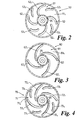
- the upper end wall 23, that is the end wall opposite to the outflow chamber, has at its internal surface 23 s an array of axial discontinuities 40 1 , 40 2 ... formed as embossments pressed at the time of drawing the contained wall to shape, and in particular comprise ribs, raised with respect to the internal surface 23 s of the wall, of relatively narrow cross-section and smooth contour side-to-side, within the constraints of being pressed unidirectionally with drawing of the container wall.
- the ribs extend between the radially inner and outer edges of the end wall, as defined by the junction with the peripheral side wall 22 and bearing tube 25, the ribs having not only a radial component of direction but also a circumferential component as a smooth and consistent curvature along their entire lengths such that at their radially outer regions they are displaced circumferentially with respect to regions inwardly thereof in a direction that is trailing with respect to the rotation direction of the rotor canister that results from ejection of liquid lubricant from the container.
- the radially outer regions are displaced with respect to the radially inner regions in the same circumferential direction as liquid is ejected from the outflow chamber by way of the reaction nozzles.
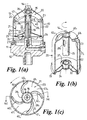
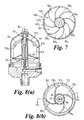
- FIGS 9(a) to 9(c) these are generally similar to the views of Figures 1(a) to 1(c) but of a further embodiment of centrifugal separator 200 including a ninth embodiment of rotor canister 220.
- Those parts of the separator housing which correspond to those described above with reference to Figure 1(a) are given like references and not described further.
- the rotor canister 220 likewise has many parts identical with rotor canister 20 and like references are again used and detailed description omitted. Where the rotor canister does differ is that the axial displacements, in the form of embossed ribs 240 1 , 240 2 , 240 3 ... have their radially outer regions circumferentially displaced in a direction that is leading, or forward, with respect to the clockwise rotation direction of the canister that results from ejection of the liquid from the outflow chamber.
- the axial displacements have been at the upper end wall of the rotor canister separation chamber, and opposite to the outflow chamber at the lower end of the canister, it will be appreciated that if the rotor is designed such that liquid is ejected from an outflow chamber at the operationally upper end of the rotor then the separation chamber inlet apertures will be moved to the lower end wall of the canister and the axial displacements formed at such lower end wall.
Landscapes
- Centrifugal Separators (AREA)
- Cyclones (AREA)
- Lubrication Details And Ventilation Of Internal Combustion Engines (AREA)
Applications Claiming Priority (3)
| Application Number | Priority Date | Filing Date | Title |
|---|---|---|---|
| GB9718564A GB2328890B (en) | 1997-09-03 | 1997-09-03 | Centrifugal separation apparatus |
| GB9718564 | 1997-09-03 | ||
| PCT/GB1998/002572 WO1999011381A1 (en) | 1997-09-03 | 1998-08-26 | Centrifugal separation apparatus |
Publications (2)
| Publication Number | Publication Date |
|---|---|
| EP1009537A1 EP1009537A1 (en) | 2000-06-21 |
| EP1009537B1 true EP1009537B1 (en) | 2002-06-12 |
Family
ID=10818385
Family Applications (1)
| Application Number | Title | Priority Date | Filing Date |
|---|---|---|---|
| EP98940398A Expired - Lifetime EP1009537B1 (en) | 1997-09-03 | 1998-08-26 | Centrifugal separation apparatus |
Country Status (7)
| Country | Link |
|---|---|
| EP (1) | EP1009537B1 (enExample) |
| JP (1) | JP2001518374A (enExample) |
| AT (1) | ATE218924T1 (enExample) |
| DE (2) | DE69806021T2 (enExample) |
| GB (1) | GB2328890B (enExample) |
| WO (1) | WO1999011381A1 (enExample) |
| ZA (1) | ZA987954B (enExample) |
Cited By (1)
| Publication number | Priority date | Publication date | Assignee | Title |
|---|---|---|---|---|
| CN111663980A (zh) * | 2020-06-09 | 2020-09-15 | 深圳市创裕达电子有限公司 | 一种智能滤芯 |
Families Citing this family (3)
| Publication number | Priority date | Publication date | Assignee | Title |
|---|---|---|---|---|
| GB9718563D0 (en) * | 1997-09-03 | 1997-11-05 | Glacier Metal Co Ltd | Centrifugal Separation Apparatus |
| US8220177B2 (en) * | 2007-05-23 | 2012-07-17 | Gala Industries, Inc. | Centrifugal pellet dryer screen with integral embossed deflector strips |
| KR101151975B1 (ko) | 2010-11-03 | 2012-06-01 | 울산대학교 산학협력단 | 복합 구동형 원심 분리기 |
Family Cites Families (9)
| Publication number | Priority date | Publication date | Assignee | Title |
|---|---|---|---|---|
| GB732132A (en) * | 1952-08-01 | 1955-06-22 | Glacier Co Ltd | Improvements in or relating to centrifugal separators |
| GB1036661A (en) * | 1964-02-26 | 1966-07-20 | Veb Zek | Improvements in or relating to centrifugal oil separators |
| JPS5620661U (enExample) * | 1979-07-25 | 1981-02-24 | ||
| US4430071A (en) * | 1982-05-27 | 1984-02-07 | Dorr-Oliver Incorporated | Feed seal for bottom feed centrifuge |
| GB8504880D0 (en) * | 1985-02-26 | 1985-03-27 | Ae Plc | Disposable cartridges |
| WO1991009251A2 (en) * | 1989-12-08 | 1991-06-27 | Reg Harris Holdings (Private) Limited | Centrifugal separator |
| GB2274413B (en) * | 1993-01-23 | 1996-07-10 | Glacier Metal Co Ltd | Oil cleaning assemblies for engines |
| US5575912A (en) * | 1995-01-25 | 1996-11-19 | Fleetguard, Inc. | Self-driven, cone-stack type centrifuge |
| US5637217A (en) * | 1995-01-25 | 1997-06-10 | Fleetguard, Inc. | Self-driven, cone-stack type centrifuge |
-
1997
- 1997-09-03 GB GB9718564A patent/GB2328890B/en not_active Expired - Fee Related
-
1998
- 1998-08-26 AT AT98940398T patent/ATE218924T1/de not_active IP Right Cessation
- 1998-08-26 EP EP98940398A patent/EP1009537B1/en not_active Expired - Lifetime
- 1998-08-26 DE DE69806021T patent/DE69806021T2/de not_active Expired - Lifetime
- 1998-08-26 WO PCT/GB1998/002572 patent/WO1999011381A1/en not_active Ceased
- 1998-08-26 JP JP2000508472A patent/JP2001518374A/ja active Pending
- 1998-09-01 ZA ZA987954A patent/ZA987954B/xx unknown
- 1998-09-03 DE DE29815879U patent/DE29815879U1/de not_active Expired - Lifetime
Cited By (1)
| Publication number | Priority date | Publication date | Assignee | Title |
|---|---|---|---|---|
| CN111663980A (zh) * | 2020-06-09 | 2020-09-15 | 深圳市创裕达电子有限公司 | 一种智能滤芯 |
Also Published As
| Publication number | Publication date |
|---|---|
| ZA987954B (en) | 1999-03-03 |
| DE69806021T2 (de) | 2003-02-06 |
| DE29815879U1 (de) | 1998-11-26 |
| GB2328890A (en) | 1999-03-10 |
| EP1009537A1 (en) | 2000-06-21 |
| GB9718564D0 (en) | 1997-11-05 |
| DE69806021D1 (de) | 2002-07-18 |
| ATE218924T1 (de) | 2002-06-15 |
| GB2328890B (en) | 2001-08-22 |
| WO1999011381A1 (en) | 1999-03-11 |
| JP2001518374A (ja) | 2001-10-16 |
Similar Documents
| Publication | Publication Date | Title |
|---|---|---|
| US7775963B2 (en) | Liquid driven centrifugal separation apparatus and open vessel rotor with improved efficiency | |
| US20150075377A1 (en) | Separator and method for separating liquid droplets from an aerosol | |
| EP0927079B1 (en) | Centrifugal separation apparatus | |
| US6602180B2 (en) | Self-driven centrifuge with vane module | |
| US6238331B1 (en) | Centrifugal separator with separation funnel | |
| JP4516260B2 (ja) | 螺旋形翼を備えた遠心分離器モジュール | |
| EP1009537B1 (en) | Centrifugal separation apparatus | |
| WO2022223222A1 (en) | A centrifugal separator for cleaning gas | |
| EP1368128B1 (en) | Centrifugal separation apparatus | |
| US20020045526A1 (en) | Molded spiral vane and liner component for a centrifuge | |
| GB2328891A (en) | Centrifugal oil filter with separation funnel arrangement | |
| US7297098B2 (en) | Centrifugal separator and rotor therefor with a recess defining a drive liquid conduit | |
| MXPA00002108A (en) | Centrifugal separation apparatus | |
| JP3660882B2 (ja) | 翼モジュールを備えた自己被動式遠心機 | |
| MXPA00002109A (en) | Centrifugal separation apaprtus | |
| CN114007720A (zh) | 用于涡轮机离心式脱气器的具有适配纵向壁的部件 |
Legal Events
| Date | Code | Title | Description |
|---|---|---|---|
| PUAI | Public reference made under article 153(3) epc to a published international application that has entered the european phase |
Free format text: ORIGINAL CODE: 0009012 |
|
| 17P | Request for examination filed |
Effective date: 20000324 |
|
| AK | Designated contracting states |
Kind code of ref document: A1 Designated state(s): AT BE DE ES FI FR GB IE IT NL SE |
|
| RAP1 | Party data changed (applicant data changed or rights of an application transferred) |
Owner name: FILTERWERK MANN & HUMMEL GMBH |
|
| RAP1 | Party data changed (applicant data changed or rights of an application transferred) |
Owner name: FILTERWERK MANN+HUMMEL GMBH |
|
| 17Q | First examination report despatched |
Effective date: 20010313 |
|
| GRAG | Despatch of communication of intention to grant |
Free format text: ORIGINAL CODE: EPIDOS AGRA |
|
| GRAG | Despatch of communication of intention to grant |
Free format text: ORIGINAL CODE: EPIDOS AGRA |
|
| GRAH | Despatch of communication of intention to grant a patent |
Free format text: ORIGINAL CODE: EPIDOS IGRA |
|
| GRAH | Despatch of communication of intention to grant a patent |
Free format text: ORIGINAL CODE: EPIDOS IGRA |
|
| GRAA | (expected) grant |
Free format text: ORIGINAL CODE: 0009210 |
|
| AK | Designated contracting states |
Kind code of ref document: B1 Designated state(s): AT BE DE ES FI FR GB IE IT NL SE |
|
| PG25 | Lapsed in a contracting state [announced via postgrant information from national office to epo] |
Ref country code: NL Free format text: LAPSE BECAUSE OF FAILURE TO SUBMIT A TRANSLATION OF THE DESCRIPTION OR TO PAY THE FEE WITHIN THE PRESCRIBED TIME-LIMIT Effective date: 20020612 Ref country code: IT Free format text: LAPSE BECAUSE OF FAILURE TO SUBMIT A TRANSLATION OF THE DESCRIPTION OR TO PAY THE FEE WITHIN THE PRESCRIBED TIME-LIMIT;WARNING: LAPSES OF ITALIAN PATENTS WITH EFFECTIVE DATE BEFORE 2007 MAY HAVE OCCURRED AT ANY TIME BEFORE 2007. THE CORRECT EFFECTIVE DATE MAY BE DIFFERENT FROM THE ONE RECORDED. Effective date: 20020612 Ref country code: FI Free format text: LAPSE BECAUSE OF FAILURE TO SUBMIT A TRANSLATION OF THE DESCRIPTION OR TO PAY THE FEE WITHIN THE PRESCRIBED TIME-LIMIT Effective date: 20020612 Ref country code: BE Free format text: LAPSE BECAUSE OF FAILURE TO SUBMIT A TRANSLATION OF THE DESCRIPTION OR TO PAY THE FEE WITHIN THE PRESCRIBED TIME-LIMIT Effective date: 20020612 Ref country code: AT Free format text: LAPSE BECAUSE OF FAILURE TO SUBMIT A TRANSLATION OF THE DESCRIPTION OR TO PAY THE FEE WITHIN THE PRESCRIBED TIME-LIMIT Effective date: 20020612 |
|
| REF | Corresponds to: |
Ref document number: 218924 Country of ref document: AT Date of ref document: 20020615 Kind code of ref document: T |
|
| REG | Reference to a national code |
Ref country code: GB Ref legal event code: FG4D |
|
| REF | Corresponds to: |
Ref document number: 69806021 Country of ref document: DE Date of ref document: 20020718 |
|
| ET | Fr: translation filed | ||
| PG25 | Lapsed in a contracting state [announced via postgrant information from national office to epo] |
Ref country code: IE Free format text: LAPSE BECAUSE OF NON-PAYMENT OF DUE FEES Effective date: 20020826 |
|
| PG25 | Lapsed in a contracting state [announced via postgrant information from national office to epo] |
Ref country code: SE Free format text: LAPSE BECAUSE OF FAILURE TO SUBMIT A TRANSLATION OF THE DESCRIPTION OR TO PAY THE FEE WITHIN THE PRESCRIBED TIME-LIMIT Effective date: 20020912 |
|
| NLV1 | Nl: lapsed or annulled due to failure to fulfill the requirements of art. 29p and 29m of the patents act | ||
| PG25 | Lapsed in a contracting state [announced via postgrant information from national office to epo] |
Ref country code: ES Free format text: LAPSE BECAUSE OF FAILURE TO SUBMIT A TRANSLATION OF THE DESCRIPTION OR TO PAY THE FEE WITHIN THE PRESCRIBED TIME-LIMIT Effective date: 20021220 |
|
| PLBE | No opposition filed within time limit |
Free format text: ORIGINAL CODE: 0009261 |
|
| STAA | Information on the status of an ep patent application or granted ep patent |
Free format text: STATUS: NO OPPOSITION FILED WITHIN TIME LIMIT |
|
| REG | Reference to a national code |
Ref country code: IE Ref legal event code: MM4A |
|
| 26N | No opposition filed |
Effective date: 20030313 |
|
| REG | Reference to a national code |
Ref country code: FR Ref legal event code: PLFP Year of fee payment: 19 |
|
| REG | Reference to a national code |
Ref country code: FR Ref legal event code: PLFP Year of fee payment: 20 |
|
| PGFP | Annual fee paid to national office [announced via postgrant information from national office to epo] |
Ref country code: GB Payment date: 20170822 Year of fee payment: 20 Ref country code: DE Payment date: 20170822 Year of fee payment: 20 Ref country code: FR Payment date: 20170822 Year of fee payment: 20 |
|
| REG | Reference to a national code |
Ref country code: DE Ref legal event code: R082 Ref document number: 69806021 Country of ref document: DE Representative=s name: VOTH, GERHARD, DIPL.-ING.(FH), DE Ref country code: DE Ref legal event code: R081 Ref document number: 69806021 Country of ref document: DE Owner name: MANN+HUMMEL GMBH, DE Free format text: FORMER OWNER: MANN + HUMMEL GMBH, 71638 LUDWIGSBURG, DE |
|
| REG | Reference to a national code |
Ref country code: DE Ref legal event code: R071 Ref document number: 69806021 Country of ref document: DE |
|
| REG | Reference to a national code |
Ref country code: GB Ref legal event code: PE20 Expiry date: 20180825 |
|
| PG25 | Lapsed in a contracting state [announced via postgrant information from national office to epo] |
Ref country code: GB Free format text: LAPSE BECAUSE OF EXPIRATION OF PROTECTION Effective date: 20180825 |