EP1009069B1 - Low profile filter connector with ferrite - Google Patents
Low profile filter connector with ferrite Download PDFInfo
- Publication number
- EP1009069B1 EP1009069B1 EP99123134A EP99123134A EP1009069B1 EP 1009069 B1 EP1009069 B1 EP 1009069B1 EP 99123134 A EP99123134 A EP 99123134A EP 99123134 A EP99123134 A EP 99123134A EP 1009069 B1 EP1009069 B1 EP 1009069B1
- Authority
- EP
- European Patent Office
- Prior art keywords
- connector
- contacts
- cable arrangement
- electrical
- ferrite
- Prior art date
- Legal status (The legal status is an assumption and is not a legal conclusion. Google has not performed a legal analysis and makes no representation as to the accuracy of the status listed.)
- Expired - Lifetime
Links
Images

Classifications
-
- H—ELECTRICITY
- H01—ELECTRIC ELEMENTS
- H01R—ELECTRICALLY-CONDUCTIVE CONNECTIONS; STRUCTURAL ASSOCIATIONS OF A PLURALITY OF MUTUALLY-INSULATED ELECTRICAL CONNECTING ELEMENTS; COUPLING DEVICES; CURRENT COLLECTORS
- H01R13/00—Details of coupling devices of the kinds covered by groups H01R12/70 or H01R24/00 - H01R33/00
- H01R13/66—Structural association with built-in electrical component
- H01R13/719—Structural association with built-in electrical component specially adapted for high frequency, e.g. with filters
Definitions
- the present invention relates to electrical connectors and, more particularly, to a connector-cable arrangement of the kind referred to in the preamble portion of patent claim 1.
- a connector-cable arrangement is known from US-5,586,902.
- US-5,489,220 discloses a filter connector having a ferrite barrel with rectangular bores.
- US-5,213,522 discloses a filter connector with ferrite blocks surrounding portions of connector pins between the pins' two connection ends.
- US-5,586,902 discloses a filter connector with a ferrite block spaced from the connector's contacts and located on conductor cables extending into the connector.
- EP 808 749 A2 discloses a connector for an airbag gas generator having a male plug connector portion and perpendicular to that an elongated housing comprising a ferrite filter and a crimping area for the link between the contact blades and the connector.
- the elongated housing is still quite high, since the crimping area has a certain height and the insulation displacement terminals could also be employed for round wire.
- US-5,586,902 discloses an electrical connector-cable arrangement, wherein the connector comprises a housing, electrical contacts and a ferrite block lodged in the housing, the contacts each having a connection area for electrical connection to a mating contact and a tail end for connection to an electrical conductor, the ferrite block and a cable fixed to the contacts. Also in this arrangement the thickness of the elongated housing is relatively big due to the crimping and the use of a cable with a circular section.
- an electrical connector comprising a housing, electrical contacts connected to the housing, and a ferrite block connected to the housing.
- the contacts each have a first connection area for electrical connection to a mating contact and a second connection area for connection to an electrical conductor.
- the ferrite block surrounds a portion of at least one of the electrical contacts at a location between the first and second connection areas.
- an electrical connector comprising a housing and electrical contacts connected to the housing.
- the electrical contacts each comprise a first female connection area for receiving a male contact and a lead extending from the first connection area at an angle of about 90°.
- the leads have flat side profiles.
- the connector further comprises at least one ferrite block surrounding the leads.
- an electrical connector comprising a housing, electrical contacts connected to the housing, and a ferrite block.
- the ferrite block surrounds portions of the electrical contacts.
- the ferrite block has two slots extending through the block. Each slot has a height less than a width of the slot.
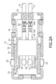
- FIG. 1 there is shown a perspective view of an electrical connector 10 incorporating features of the present invention.
- an electrical connector 10 incorporating features of the present invention.
- the present invention will be described with reference to the embodiments shown in the drawings, it should be understood that the present invention can be embodied in many alternate forms of embodiments.
- any suitable size, shape or type of elements or materials could be used.
- the connector 10 in this embodiment, is for use in connecting electrical conductors 14, 15 with an air bag gas generator 12. However, the connector 10 could be used to connect conductors with other devices.
- the connector 10 generally comprises a housing 16, electrical contacts 18 and a ferrite block or hood 20.
- the housing 16 comprises a first housing piece 22 and a second housing piece 24.
- the first housing piece 22 includes two cantilevered finger actuatable deflectable latches 26, two separate receiving areas 28, and two holes 30 through a bottom face 32 of the housing into the receiving areas 28.
- the housing 16, at the bottom of the front section 34, is adapted to be plugged into a socket 36 of the gas generator 12.
- the latches 26 are adapted to latch with the latch surfaces in the socket 36.
- additional connector position assurance means is provided to prevent the connector 10 from accidentally being disengaged from the gas generator 12.
- the second housing piece 24 is connected to the first housing piece 22 after the contacts 18 and ferrite hood 20 are located in the first housing piece 22.
- Fig. 3 shows the first housing piece 22 before the second housing piece is connected thereon.
- the second housing piece could be molded onto the first housing piece.
- the first housing piece is provided with two holes 52, 54 in its rear end; hole 52 for providing a passageway for the conductors 14, 15 out the rear end, and hole 54 for access for a tool (not shown) to crimp the tabs 41 on the conductors 14, 15.
- the electrical contacts 18 each comprise a female contact area 38 and a connection area 40 for connection to the electrical conductors 14, 15.
- the contacts 18 are comprised of stamped and formed sheet metal.
- the contacts each comprise a first member 18a and a second member 18b.
- the first member 18a is preferably a one-piece member which comprises the female contact area 38 and a lead section 46.
- the first member 18a could be provided as a multi-piece member.
- the second member 18b is preferably a one-piece member with tabs 41 that form a conductor connection area 40.
- the second member 18b is preferably stationarily attached to the end of the lead section 46, such as by welding, after the lead sections 46 are located in the ferrite block 20.
- the female contact area 38 has two spring contact arms 42 and a leading end positioner 44.
- the socket 36 has two male pin contacts -(not shown) at a fixed spacing relative to each other that are received in the two female contact areas 38 through the holes 30 in the housing 12.
- the lead section 46 of each contact 18 extends between the female contact area 38 and the conductor connection area 40. In this embodiment the lead section 46 has a 90° bend for use in providing a right angle connector. However, the lead section could be straight for an in-line connector.
- the front end 47 of the lead section 46 has a hump shape to provide additional space for the top end 39 of the female contact area 38 to extend past the bottom of the ferrite block 20 and closer to the top of the housing 16.
- the lead section 46 has a flat side profile with a general cross-sectional rectangular shape along its length. This shape is easily provided if sheet metal is used to form the first member 18a, or at least used to form the lead section 46.
- the length of the lead section 46 is longer than the length of the ferrite block 20.
- the lead sections 46 extend through the ferrite block and have a tail section 48 that extend past the rear end of the ferrite block 20.
- the conductors 14, 15 are soldered or welded to the connector areas 40. Thus, the contacts 18 are able to electrically connect the male pin contacts to the conductors 14, 15.
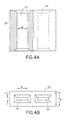
- the ferrite block 20 is shown.
- the ferrite block 20 could be provided as separate spaced members on respective ones of the contacts 18.
- the ferrite block is comprised of electrically nonconductive ferrite oxide having a general rectangular box shape with two parallel side-by-side holes 50 passing therethrough from a front to a rear of the block
- the holes 50 have a general cross-sectionally rectangular shape along the length of the block with a height H being smaller than a width W.
- the cross-sectional shape of the holes 50 substantially match the cross-sectional shape of the lead sections 46.
- the two lead sections 46 extend through the holes 50.
- the second members 18b are then attached to the tail sections 48 after the block 20 is positioned on the lead sections.
- the assembly is then inserted into the first housing piece 22 with the female contact areas 38 received in the receiving areas 28 and the ferrite block 20 received in its receiving area 21 of the first housing piece 22.
- the second housing piece 24 is then connected to the first housing piece 22 to capture the assembly between the two housing pieces and provide strain relief for the conductors 14, 15.
- the lead sections 46 With providing the lead sections 46 with flat shapes, the height H of the holes 50 can be made small.
- the height H 8 of the block 20 can be reduced, compared to ferrite blocks used with non-flat shaped conductors, without reducing the effective working height of the ferrite material on top and beneath the lead section 46.
- the height H C which the connector extends past the end of the gas generator 12 (see Fig.
- a unique advantage of the present invention relates to the relative positioning of the ferrite block 20 on the contacts 18.
- the ferrite block 20 is located on the lead sections 46 between the two connection areas 38, 40. Even if tabs 41 form antennas, because the connection area 40 is located behind the ferrite block 20, the block 20 can attenuate high frequency signals that might come from the tabs 41 before the signals reach the connection areas 38.
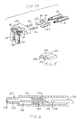
- Fig. 5 shows a perspective view of an end of a flat conductor cable 100 which is connected to the connector shown in Fig. 3 without use of the contact second members 18b.
- the cable 100 has conductors 102, 104 and electrical insulation 106.
- the spacing between the conductors 102, 104 and the spacing between the tail ends 48 of the contacts 18 would be the same.
- the ends of the conductors 102, 104 could'merely be placed on the tail ends 48 and soldered onto the tail ends.
- Fig. 6 is a cross-sectional view of an alternate embodiment of the connector.
- the connector 120 is a straight or in-line connector rather than a right angle connector.
- the connector 120 has a housing 122, contacts 124, and a ferrite block 126.
- the contacts 124 have a front female connection area 128, an integral lead 130 and a rear connection area 132.
- Conductors 134 pass through the rear end of the housing 122 and are crimped onto the rear connection area 132.
- the contacts have a first member 136 which forms the front connection area 128 and lead 130, and a second member 138.
- the second member is stationarily attached to the first member 136 and forms the rear connection area 132.
- the ferrite block 126 is located between and spaced from the two connection areas 128, 132.
- the connection areas 128, 132 and lead 130 are aligned in a straight row, one behind the other.
Landscapes
- Details Of Connecting Devices For Male And Female Coupling (AREA)
- Coils Or Transformers For Communication (AREA)
Abstract
Description
- The present invention relates to electrical connectors and, more particularly, to a connector-cable arrangement of the kind referred to in the preamble portion of
patent claim 1. Such a connector-cable arrangement is known from US-5,586,902. - US-5,489,220 discloses a filter connector having a ferrite barrel with rectangular bores. US-5,213,522 discloses a filter connector with ferrite blocks surrounding portions of connector pins between the pins' two connection ends. US-5,586,902 discloses a filter connector with a ferrite block spaced from the connector's contacts and located on conductor cables extending into the connector.
- EP 808 749 A2 discloses a connector for an airbag gas generator having a male plug connector portion and perpendicular to that an elongated housing comprising a ferrite filter and a crimping area for the link between the contact blades and the connector. The elongated housing is still quite high, since the crimping area has a certain height and the insulation displacement terminals could also be employed for round wire.
- US-5,586,902 discloses an electrical connector-cable arrangement, wherein the connector comprises a housing, electrical contacts and a ferrite block lodged in the housing, the contacts each having a connection area for electrical connection to a mating contact and a tail end for connection to an electrical conductor, the ferrite block and a cable fixed to the contacts. Also in this arrangement the thickness of the elongated housing is relatively big due to the crimping and the use of a cable with a circular section.
- It is therefore an object of the present invention to improve a connector-cable arrangement of the kind as referred to in the preamble portion of
claim 1 such that the thickness of the elongated housing portion of the connector can be further reduced. - This object is accomplished with a connector-cable arrangement as claimed.
- Dependent claims are directed on features of preferred embodiments of the invention.
- In accordance with one embodiment of the present invention an electrical connector is provided comprising a housing, electrical contacts connected to the housing, and a ferrite block connected to the housing. The contacts each have a first connection area for electrical connection to a mating contact and a second connection area for connection to an electrical conductor. The ferrite block surrounds a portion of at least one of the electrical contacts at a location between the first and second connection areas.
- In accordance with another embodiment of the present invention an electrical connector is provided comprising a housing and electrical contacts connected to the housing. The electrical contacts each comprise a first female connection area for receiving a male contact and a lead extending from the first connection area at an angle of about 90°. The leads have flat side profiles. The connector further comprises at least one ferrite block surrounding the leads.
- In accordance with another embodiment of the present invention an electrical connector is provided comprising a housing, electrical contacts connected to the housing, and a ferrite block. The ferrite block surrounds portions of the electrical contacts. The ferrite block has two slots extending through the block. Each slot has a height less than a width of the slot.
- The foregoing aspects and other features of the present invention are explained in the following description, taken in connection with the accompanying drawings, wherein:
- Fig. 1 is a perspective view of an electrical connector incorporating features of the present invention connected to an air bag gas generator;
- Fig 2A is a cross-sectional view of the connector shown in Fig. 1;
- Fig 2B is an exploded perspective view of the contacts, ferrite block and conductors used with the connector shown in Fig. 1;
- Fig. 3 is a partial cross-sectional view of the connector shown in Fig. 1 without the intermediate crimp members;
- Fig 4A is a top plan view with a cut-away section of the ferrite block shown in Figs. 2A-3;
- Fig 4B is an elevational front view of the ferrite block shown in Fig. 4A;
- Fig. 5 is a perspective view of an end of a flat conductor cable used with the connector shown in Fig. 3; and
- Fig. 6 is a cross-sectional view of an alternate embodiment of the electrical connector.
-
- Referring to Fig. 1, there is shown a perspective view of an
electrical connector 10 incorporating features of the present invention. Although the present invention will be described with reference to the embodiments shown in the drawings, it should be understood that the present invention can be embodied in many alternate forms of embodiments. In addition, any suitable size, shape or type of elements or materials could be used. - The
connector 10, in this embodiment, is for use in connectingelectrical conductors bag gas generator 12. However, theconnector 10 could be used to connect conductors with other devices. Referring also to Figs. 2A, 2B, 3 theconnector 10 generally comprises ahousing 16,electrical contacts 18 and a ferrite block orhood 20. Thehousing 16 comprises afirst housing piece 22 and asecond housing piece 24. Thefirst housing piece 22 includes two cantilevered finger actuatabledeflectable latches 26, two separate receiving areas 28, and twoholes 30 through abottom face 32 of the housing into the receiving areas 28. Thehousing 16, at the bottom of thefront section 34, is adapted to be plugged into asocket 36 of thegas generator 12. Thelatches 26 are adapted to latch with the latch surfaces in thesocket 36. Preferably, additional connector position assurance means is provided to prevent theconnector 10 from accidentally being disengaged from thegas generator 12. Thesecond housing piece 24 is connected to thefirst housing piece 22 after thecontacts 18 andferrite hood 20 are located in thefirst housing piece 22. However, in alternate embodiments other types of housings or housing components could be provided. Fig. 3 shows thefirst housing piece 22 before the second housing piece is connected thereon. In an alternate embodiment the second housing piece could be molded onto the first housing piece. In this embodiment the first housing piece is provided with twoholes hole 52 for providing a passageway for theconductors hole 54 for access for a tool (not shown) to crimp thetabs 41 on theconductors - The
electrical contacts 18 each comprise afemale contact area 38 and aconnection area 40 for connection to theelectrical conductors contacts 18 are comprised of stamped and formed sheet metal. In the embodiment shown in Figs. 2A and 2B the contacts each comprise afirst member 18a and asecond member 18b. Thefirst member 18a is preferably a one-piece member which comprises thefemale contact area 38 and alead section 46. However, thefirst member 18a could be provided as a multi-piece member. Thesecond member 18b is preferably a one-piece member withtabs 41 that form aconductor connection area 40. Thesecond member 18b is preferably stationarily attached to the end of thelead section 46, such as by welding, after thelead sections 46 are located in theferrite block 20. Thefemale contact area 38 has twospring contact arms 42 and a leadingend positioner 44. Thesocket 36 has two male pin contacts -(not shown) at a fixed spacing relative to each other that are received in the twofemale contact areas 38 through theholes 30 in thehousing 12. Thelead section 46 of eachcontact 18 extends between thefemale contact area 38 and theconductor connection area 40. In this embodiment thelead section 46 has a 90° bend for use in providing a right angle connector. However, the lead section could be straight for an in-line connector. In this embodiment thefront end 47 of thelead section 46 has a hump shape to provide additional space for thetop end 39 of thefemale contact area 38 to extend past the bottom of theferrite block 20 and closer to the top of thehousing 16. Thus, the length of thefront plug section 34 can be reduced while still keeping the length of thefemale contact area 38 the same or even larger then in the prior art. This allows the engagement length with the male contacts to be kept the same or even increased. Thelead section 46 has a flat side profile with a general cross-sectional rectangular shape along its length. This shape is easily provided if sheet metal is used to form thefirst member 18a, or at least used to form thelead section 46. The length of thelead section 46 is longer than the length of theferrite block 20. Thelead sections 46 extend through the ferrite block and have atail section 48 that extend past the rear end of theferrite block 20. Theconductors connector areas 40. Thus, thecontacts 18 are able to electrically connect the male pin contacts to theconductors - Referring also to Figs. 4A and 4B, the
ferrite block 20 is shown. In an alternate embodiment theferrite block 20 could be provided as separate spaced members on respective ones of thecontacts 18. In this embodiment the ferrite block is comprised of electrically nonconductive ferrite oxide having a general rectangular box shape with two parallel side-by-side holes 50 passing therethrough from a front to a rear of the block Theholes 50 have a general cross-sectionally rectangular shape along the length of the block with a height H being smaller than a width W. The cross-sectional shape of theholes 50 substantially match the cross-sectional shape of thelead sections 46. The twolead sections 46 extend through theholes 50. Thesecond members 18b are then attached to thetail sections 48 after theblock 20 is positioned on the lead sections. The assembly is then inserted into thefirst housing piece 22 with thefemale contact areas 38 received in the receiving areas 28 and theferrite block 20 received in its receiving area 21 of thefirst housing piece 22. Thesecond housing piece 24 is then connected to thefirst housing piece 22 to capture the assembly between the two housing pieces and provide strain relief for theconductors lead sections 46 with flat shapes, the height H of theholes 50 can be made small. Thus, the height H8 of theblock 20 can be reduced, compared to ferrite blocks used with non-flat shaped conductors, without reducing the effective working height of the ferrite material on top and beneath thelead section 46. With this reduction in the height HB of the ferrite block, the height HC which the connector extends past the end of the gas generator 12 (see Fig. 1) can be reduced. Hence, a smaller height low profile filter connector can be provided. For example, in a prior art connector, such as in U.S. Patent 5,586,902, the holes in the ferrite block would be about 2.6mm high and the length of the ferrite block would be about 8.4mm with a connector height of about 5.3mm. With the present invention a same frequency attenuation can be provided with flat 0.25mm high leads which are about 12mm long to provide a connector height Hc of about 2.6mm. Thus, the connector height can be reduced in half. This can be of great advantage to allow theconnector 10 to be used for both a front air bag or a side air bag in the small width of a car door, or even a seat belt air bag. Thus, different types of connectors do not need to be used in different applications; a universal right angle connector for use with all types of air bag gas generators can be provided. A unique advantage of the present invention relates to the relative positioning of theferrite block 20 on thecontacts 18. Theferrite block 20 is located on thelead sections 46 between the twoconnection areas tabs 41 form antennas, because theconnection area 40 is located behind theferrite block 20, theblock 20 can attenuate high frequency signals that might come from thetabs 41 before the signals reach theconnection areas 38. - Fig. 5 shows a perspective view of an end of a
flat conductor cable 100 which is connected to the connector shown in Fig. 3 without use of the contactsecond members 18b. Thecable 100 hasconductors electrical insulation 106. The spacing between theconductors contacts 18 would be the same. Thus, the ends of theconductors - Fig. 6 is a cross-sectional view of an alternate embodiment of the connector. In this embodiment the
connector 120 is a straight or in-line connector rather than a right angle connector. Theconnector 120 has ahousing 122,contacts 124, and aferrite block 126. Thecontacts 124 have a frontfemale connection area 128, anintegral lead 130 and arear connection area 132.Conductors 134 pass through the rear end of thehousing 122 and are crimped onto therear connection area 132. The contacts have afirst member 136 which forms thefront connection area 128 and lead 130, and asecond member 138. The second member is stationarily attached to thefirst member 136 and forms therear connection area 132. Theferrite block 126 is located between and spaced from the twoconnection areas connection areas - It should be understood that the foregoing description is only illustrative of the invention. Various alternatives and modifications can be devised by those skilled in the art without departing from the invention. Accordingly, the present invention is intended to embrace all such alternatives, modifications and variances which fall within the scope of the appended claims.
Claims (10)
- An electrical connector-cable arrangement (10, 100) wherein the connector (10) comprises a housing (16), electrical contacts (18) and a ferrite block (20) lodged in the housing (16), the contacts (18) each having a connection area (18a) for electrical connection to a mating contact, a tail end (48) for connection to an electrical conductor (100) and a front end (47) for connection to a female contact area,
the ferrite block (20) and a cable (100) fixed to the contacts (18), said ferrite block (20) surrounds a portion of at least one of the electrical contacts (18) at a location between the connection area (18a) and the tail end (48) and said cable is a flat conductor cable (100) with two conductors (102, 104),
the spacing between which corresponds to the spacing between the tail ends (48) of the electrical contacts (18)
characterized in that
said front end (47) of the lead section (46) has a hump shape, and in that the tail ends (48) and the contacts (18) are soldered together. - A connector-cable arrangement as in claim 1, wherein the electrical contacts (18) have a flat shape, said ferrite blocks being a unitary block.
- A connector-cable arrangement as in claim 1, wherein the connection area (18a) and at least a portion of the electrical contact (18) are orientated at a right angle to each other.
- A connector-cable arrangement (10) as in claim 1, wherein the ferrite block (20) comprises at least one enclosed channel therethrough with the at least one contact (18) extending through the channel, the channel having a cross-sectionally rectangular shape with rectangular shaped openings (50) into the channel at opposite ends of the block (20), which substantially matches the cross-sectional shape of the lead sections (46).
- A connector-cable arrangement as in claim 4, wherein the ferrite block (20) has two of the channels (50) therein arranged side-by-side and spaced from each other.
- A connector-cable arrangement as in claim 5, wherein a height of the channel (50) is less than a width of the channel (50).
- A connector-cable arrangement as in claim 1, wherein the first connection area (128), the second connection area (132) and the lead portion (130) are aligned in a straight row.
- A connector-cable arrangement as in claim 1, wherein the conductor connection areas (38, 40) have a same shape as the leads.
- A connector-cable arrangement as in claim 1, wherein the second housing piece is molded onto the first housing piece.
- A connector-cable arrangement as in claim 1, wherein the first housing piece is provided with at least one hole (54) for access for a tool to crimp the tabs (41) on the conductors (14, 15).
Applications Claiming Priority (2)
| Application Number | Priority Date | Filing Date | Title |
|---|---|---|---|
| US206142 | 1998-12-07 | ||
| US09/206,142 US6234843B1 (en) | 1998-12-07 | 1998-12-07 | Low profile filter connector with ferrite |
Publications (3)
| Publication Number | Publication Date |
|---|---|
| EP1009069A2 EP1009069A2 (en) | 2000-06-14 |
| EP1009069A3 EP1009069A3 (en) | 2000-08-09 |
| EP1009069B1 true EP1009069B1 (en) | 2003-03-26 |
Family
ID=22765152
Family Applications (1)
| Application Number | Title | Priority Date | Filing Date |
|---|---|---|---|
| EP99123134A Expired - Lifetime EP1009069B1 (en) | 1998-12-07 | 1999-11-19 | Low profile filter connector with ferrite |
Country Status (4)
| Country | Link |
|---|---|
| US (1) | US6234843B1 (en) |
| EP (1) | EP1009069B1 (en) |
| AT (1) | ATE235753T1 (en) |
| DE (1) | DE69906227T2 (en) |
Cited By (1)
| Publication number | Priority date | Publication date | Assignee | Title |
|---|---|---|---|---|
| EP1117159A2 (en) * | 1999-12-24 | 2001-07-18 | Sumitomo Wiring Systems, Ltd. | Connector |
Families Citing this family (11)
| Publication number | Priority date | Publication date | Assignee | Title |
|---|---|---|---|---|
| US6547596B1 (en) | 2000-05-30 | 2003-04-15 | Amphenol-Tuchel Electronics Gmbh | Filtered electrical connector with ferrite member and coil |
| JP2003249308A (en) * | 2002-02-25 | 2003-09-05 | Tyco Electronics Amp Kk | Electrical connector assembly |
| US6997750B2 (en) | 2003-07-23 | 2006-02-14 | Fci Americas Technology, Inc. | Electrical connector contact |
| DE102004020933B3 (en) * | 2004-04-28 | 2005-12-29 | Tyco Electronics Amp Gmbh | Plug, in particular Zündpillenstecker |
| DE102005007066B3 (en) * | 2005-02-16 | 2006-10-05 | Tyco Electronics Amp Gmbh | Miniaturized electrical plug unit with improved crimpability |
| DE102005021375B4 (en) | 2005-05-04 | 2007-02-01 | Yazaki Europe Ltd., Hemel Hempstead | Connectors, in particular for airbag ignition systems |
| CN1967947B (en) * | 2005-11-14 | 2011-06-29 | 富士康(昆山)电脑接插件有限公司 | Cable linker assembly and its assembly method |
| US8425254B2 (en) * | 2007-03-19 | 2013-04-23 | Fci Automotive Holding | Electrical connector with ferrite block assembly |
| US7556537B2 (en) * | 2007-11-15 | 2009-07-07 | Gm Global Technology Operations, Inc. | Solenoid and connector assembly |
| WO2010029391A1 (en) * | 2008-09-10 | 2010-03-18 | Fci | Electrical contact, set of electrical contact, product and assembly comprising such an electrical contact, its method of manufacture and method of electrical connection |
| US8661985B2 (en) * | 2012-04-18 | 2014-03-04 | Autoliv Asp, Inc. | Low-profile igniter assemblies adapted for use with inflatable airbag systems |
Citations (1)
| Publication number | Priority date | Publication date | Assignee | Title |
|---|---|---|---|---|
| US5241910A (en) * | 1991-04-05 | 1993-09-07 | Morton International, Inc. | Universal squib connector for a gas generator |
Family Cites Families (7)
| Publication number | Priority date | Publication date | Assignee | Title |
|---|---|---|---|---|
| US4695105A (en) * | 1984-12-20 | 1987-09-22 | Amp Incorporated | Filtered electrical receptacle |
| US4648681A (en) * | 1984-12-20 | 1987-03-10 | Amp Incorporated | Filtered electrical plug |
| US5200574A (en) | 1991-04-05 | 1993-04-06 | Morton International, Inc. | Universal squib connector |
| JPH06103636B2 (en) | 1991-07-19 | 1994-12-14 | 三菱マテリアル株式会社 | Connector with filter |
| WO1994010748A1 (en) | 1992-10-30 | 1994-05-11 | Berg Technology, Inc. | Filter connector arrangement having a ferrite barrel with a rectangular bore |
| DE4317344A1 (en) | 1993-05-25 | 1994-12-01 | Framatome Connectors Int | Electrical connector |
| US5895282A (en) * | 1996-05-24 | 1999-04-20 | Thomas & Betts Corporation | Connector for airbag gas generator |
-
1998
- 1998-12-07 US US09/206,142 patent/US6234843B1/en not_active Expired - Lifetime
-
1999
- 1999-11-19 DE DE69906227T patent/DE69906227T2/en not_active Expired - Lifetime
- 1999-11-19 EP EP99123134A patent/EP1009069B1/en not_active Expired - Lifetime
- 1999-11-19 AT AT99123134T patent/ATE235753T1/en not_active IP Right Cessation
Patent Citations (1)
| Publication number | Priority date | Publication date | Assignee | Title |
|---|---|---|---|---|
| US5241910A (en) * | 1991-04-05 | 1993-09-07 | Morton International, Inc. | Universal squib connector for a gas generator |
Cited By (2)
| Publication number | Priority date | Publication date | Assignee | Title |
|---|---|---|---|---|
| EP1117159A2 (en) * | 1999-12-24 | 2001-07-18 | Sumitomo Wiring Systems, Ltd. | Connector |
| EP1117159B1 (en) * | 1999-12-24 | 2009-05-20 | Sumitomo Wiring Systems, Ltd. | Connector |
Also Published As
| Publication number | Publication date |
|---|---|
| DE69906227D1 (en) | 2003-04-30 |
| EP1009069A3 (en) | 2000-08-09 |
| US6234843B1 (en) | 2001-05-22 |
| EP1009069A2 (en) | 2000-06-14 |
| DE69906227T2 (en) | 2004-02-05 |
| ATE235753T1 (en) | 2003-04-15 |
Similar Documents
| Publication | Publication Date | Title |
|---|---|---|
| US6368154B1 (en) | Shielded electrical connector with ground contact spring | |
| JP3565161B2 (en) | Power connector | |
| US5380223A (en) | High density electrical connector | |
| EP0761028B1 (en) | Electrical connector with guides | |
| US4428636A (en) | Multi-contact connectors for closely spaced conductors | |
| EP0795929B1 (en) | Electric connector assembly with improved retention characteristics | |
| US7229298B2 (en) | Electrical connector having an improved grounding path | |
| EP1009070B1 (en) | Filtered electrical connector with multiple ferrite members | |
| CN113612081B (en) | Sub-connector and chip thereof | |
| EP1009069B1 (en) | Low profile filter connector with ferrite | |
| US6488520B1 (en) | Electrical connector assembly with shorting members | |
| US6299476B1 (en) | Electrical connector with a flexible circuit and rigidizer subassembly and a spring | |
| KR101157672B1 (en) | Connector | |
| US5567169A (en) | Electrostatic discharge conductor to shell continuity | |
| US20040053532A1 (en) | Low crosstalk insulation displacement connector for terminating cable to circuit board | |
| EP0795930B1 (en) | High contact force pin-receiving electrical contact | |
| CN111883962A (en) | Electric connector assembly and electric connector assembly | |
| GB2276283A (en) | Electrical connector with short-circuiting facility | |
| CN114175410A (en) | Safe, stable and compact connector | |
| EP0330497A1 (en) | Blind mate shielded input/output connector assembly | |
| EP0937318B1 (en) | Female terminal with protective sleeve | |
| US7470127B2 (en) | Electrical connector assembly | |
| US7052324B2 (en) | Plug connector having a damping element | |
| CN110808493A (en) | Electrical connector | |
| EP1195852B1 (en) | Improvements to flexible circuit assemblies |
Legal Events
| Date | Code | Title | Description |
|---|---|---|---|
| PUAI | Public reference made under article 153(3) epc to a published international application that has entered the european phase |
Free format text: ORIGINAL CODE: 0009012 |
|
| AK | Designated contracting states |
Kind code of ref document: A2 Designated state(s): AT BE CH CY DE DK ES FI FR GB GR IE IT LI LU MC NL PT SE |
|
| AX | Request for extension of the european patent |
Free format text: AL;LT;LV;MK;RO;SI |
|
| PUAL | Search report despatched |
Free format text: ORIGINAL CODE: 0009013 |
|
| AK | Designated contracting states |
Kind code of ref document: A3 Designated state(s): AT BE CH CY DE DK ES FI FR GB GR IE IT LI LU MC NL PT SE |
|
| AX | Request for extension of the european patent |
Free format text: AL;LT;LV;MK;RO;SI |
|
| 17P | Request for examination filed |
Effective date: 20001128 |
|
| AKX | Designation fees paid |
Free format text: AT BE CH CY DE DK ES FI FR GB GR IE IT LI LU MC NL PT SE |
|
| 17Q | First examination report despatched |
Effective date: 20010724 |
|
| GRAH | Despatch of communication of intention to grant a patent |
Free format text: ORIGINAL CODE: EPIDOS IGRA |
|
| GRAH | Despatch of communication of intention to grant a patent |
Free format text: ORIGINAL CODE: EPIDOS IGRA |
|
| RAP1 | Party data changed (applicant data changed or rights of an application transferred) |
Owner name: FCI |
|
| GRAA | (expected) grant |
Free format text: ORIGINAL CODE: 0009210 |
|
| AK | Designated contracting states |
Designated state(s): AT BE CH CY DE DK ES FI FR GB GR IE IT LI LU MC NL PT SE |
|
| PG25 | Lapsed in a contracting state [announced via postgrant information from national office to epo] |
Ref country code: NL Free format text: LAPSE BECAUSE OF FAILURE TO SUBMIT A TRANSLATION OF THE DESCRIPTION OR TO PAY THE FEE WITHIN THE PRESCRIBED TIME-LIMIT Effective date: 20030326 Ref country code: LI Free format text: LAPSE BECAUSE OF FAILURE TO SUBMIT A TRANSLATION OF THE DESCRIPTION OR TO PAY THE FEE WITHIN THE PRESCRIBED TIME-LIMIT Effective date: 20030326 Ref country code: GR Free format text: LAPSE BECAUSE OF FAILURE TO SUBMIT A TRANSLATION OF THE DESCRIPTION OR TO PAY THE FEE WITHIN THE PRESCRIBED TIME-LIMIT Effective date: 20030326 Ref country code: FI Free format text: LAPSE BECAUSE OF FAILURE TO SUBMIT A TRANSLATION OF THE DESCRIPTION OR TO PAY THE FEE WITHIN THE PRESCRIBED TIME-LIMIT Effective date: 20030326 Ref country code: CH Free format text: LAPSE BECAUSE OF FAILURE TO SUBMIT A TRANSLATION OF THE DESCRIPTION OR TO PAY THE FEE WITHIN THE PRESCRIBED TIME-LIMIT Effective date: 20030326 Ref country code: BE Free format text: LAPSE BECAUSE OF FAILURE TO SUBMIT A TRANSLATION OF THE DESCRIPTION OR TO PAY THE FEE WITHIN THE PRESCRIBED TIME-LIMIT Effective date: 20030326 Ref country code: AT Free format text: LAPSE BECAUSE OF FAILURE TO SUBMIT A TRANSLATION OF THE DESCRIPTION OR TO PAY THE FEE WITHIN THE PRESCRIBED TIME-LIMIT Effective date: 20030326 |
|
| REG | Reference to a national code |
Ref country code: GB Ref legal event code: FG4D |
|
| REG | Reference to a national code |
Ref country code: CH Ref legal event code: EP |
|
| REF | Corresponds to: |
Ref document number: 69906227 Country of ref document: DE Date of ref document: 20030430 Kind code of ref document: P |
|
| REG | Reference to a national code |
Ref country code: IE Ref legal event code: FG4D |
|
| PG25 | Lapsed in a contracting state [announced via postgrant information from national office to epo] |
Ref country code: SE Free format text: LAPSE BECAUSE OF FAILURE TO SUBMIT A TRANSLATION OF THE DESCRIPTION OR TO PAY THE FEE WITHIN THE PRESCRIBED TIME-LIMIT Effective date: 20030626 Ref country code: PT Free format text: LAPSE BECAUSE OF FAILURE TO SUBMIT A TRANSLATION OF THE DESCRIPTION OR TO PAY THE FEE WITHIN THE PRESCRIBED TIME-LIMIT Effective date: 20030626 Ref country code: DK Free format text: LAPSE BECAUSE OF FAILURE TO SUBMIT A TRANSLATION OF THE DESCRIPTION OR TO PAY THE FEE WITHIN THE PRESCRIBED TIME-LIMIT Effective date: 20030626 |
|
| NLV1 | Nl: lapsed or annulled due to failure to fulfill the requirements of art. 29p and 29m of the patents act | ||
| PG25 | Lapsed in a contracting state [announced via postgrant information from national office to epo] |
Ref country code: ES Free format text: LAPSE BECAUSE OF FAILURE TO SUBMIT A TRANSLATION OF THE DESCRIPTION OR TO PAY THE FEE WITHIN THE PRESCRIBED TIME-LIMIT Effective date: 20030930 |
|
| REG | Reference to a national code |
Ref country code: CH Ref legal event code: PL |
|
| ET | Fr: translation filed | ||
| PG25 | Lapsed in a contracting state [announced via postgrant information from national office to epo] |
Ref country code: LU Free format text: LAPSE BECAUSE OF NON-PAYMENT OF DUE FEES Effective date: 20031119 Ref country code: IE Free format text: LAPSE BECAUSE OF NON-PAYMENT OF DUE FEES Effective date: 20031119 Ref country code: CY Free format text: LAPSE BECAUSE OF FAILURE TO SUBMIT A TRANSLATION OF THE DESCRIPTION OR TO PAY THE FEE WITHIN THE PRESCRIBED TIME-LIMIT Effective date: 20031119 |
|
| PG25 | Lapsed in a contracting state [announced via postgrant information from national office to epo] |
Ref country code: MC Free format text: LAPSE BECAUSE OF NON-PAYMENT OF DUE FEES Effective date: 20031130 |
|
| PLBE | No opposition filed within time limit |
Free format text: ORIGINAL CODE: 0009261 |
|
| STAA | Information on the status of an ep patent application or granted ep patent |
Free format text: STATUS: NO OPPOSITION FILED WITHIN TIME LIMIT |
|
| 26N | No opposition filed |
Effective date: 20031230 |
|
| REG | Reference to a national code |
Ref country code: IE Ref legal event code: MM4A |
|
| REG | Reference to a national code |
Ref country code: FR Ref legal event code: CA |
|
| REG | Reference to a national code |
Ref country code: FR Ref legal event code: TP |
|
| REG | Reference to a national code |
Ref country code: GB Ref legal event code: 732E Free format text: REGISTERED BETWEEN 20110922 AND 20110928 |
|
| REG | Reference to a national code |
Ref country code: DE Ref legal event code: R082 Ref document number: 69906227 Country of ref document: DE Representative=s name: BEETZ & PARTNER MBB PATENT- UND RECHTSANWAELTE, DE Effective date: 20120419 Ref country code: DE Ref legal event code: R082 Ref document number: 69906227 Country of ref document: DE Representative=s name: BEETZ & PARTNER MBB PATENTANWAELTE, DE Effective date: 20120419 Ref country code: DE Ref legal event code: R082 Ref document number: 69906227 Country of ref document: DE Representative=s name: BEETZ & PARTNER PATENT- UND RECHTSANWAELTE, DE Effective date: 20120419 Ref country code: DE Ref legal event code: R081 Ref document number: 69906227 Country of ref document: DE Owner name: DELPHI INTERNATIONAL OPERATIONS LUXEMBOURG S.A, LU Free format text: FORMER OWNER: FCI, PARIS, FR Effective date: 20120419 |
|
| REG | Reference to a national code |
Ref country code: DE Ref legal event code: R082 Ref document number: 69906227 Country of ref document: DE Representative=s name: BEETZ & PARTNER MBB PATENT- UND RECHTSANWAELTE, DE Effective date: 20120628 Ref country code: DE Ref legal event code: R082 Ref document number: 69906227 Country of ref document: DE Representative=s name: BEETZ & PARTNER MBB PATENTANWAELTE, DE Effective date: 20120628 Ref country code: DE Ref legal event code: R082 Ref document number: 69906227 Country of ref document: DE Representative=s name: BEETZ & PARTNER PATENT- UND RECHTSANWAELTE, DE Effective date: 20120628 Ref country code: DE Ref legal event code: R081 Ref document number: 69906227 Country of ref document: DE Owner name: DELPHI INTERNATIONAL OPERATIONS LUXEMBOURG S.A, LU Free format text: FORMER OWNER: FCI, GUYANCOURT, FR Effective date: 20120628 |
|
| REG | Reference to a national code |
Ref country code: FR Ref legal event code: TP Owner name: DELPHI INTERNATIONAL OPERATIONS LUXEMBOURG S.A, LU Effective date: 20140715 |
|
| REG | Reference to a national code |
Ref country code: DE Ref legal event code: R082 Ref document number: 69906227 Country of ref document: DE Representative=s name: BEETZ & PARTNER PATENT- UND RECHTSANWAELTE, DE |
|
| REG | Reference to a national code |
Ref country code: DE Ref legal event code: R082 Ref document number: 69906227 Country of ref document: DE Representative=s name: BEETZ & PARTNER MBB PATENT- UND RECHTSANWAELTE, DE Effective date: 20141106 Ref country code: DE Ref legal event code: R082 Ref document number: 69906227 Country of ref document: DE Representative=s name: BEETZ & PARTNER MBB PATENTANWAELTE, DE Effective date: 20141106 Ref country code: DE Ref legal event code: R082 Ref document number: 69906227 Country of ref document: DE Representative=s name: BEETZ & PARTNER PATENT- UND RECHTSANWAELTE, DE Effective date: 20141106 Ref country code: DE Ref legal event code: R081 Ref document number: 69906227 Country of ref document: DE Owner name: DELPHI INTERNATIONAL OPERATIONS LUXEMBOURG S.A, LU Free format text: FORMER OWNER: FCI AUTOMOTIVE HOLDING, GUYANCOURT, FR Effective date: 20141106 |
|
| REG | Reference to a national code |
Ref country code: GB Ref legal event code: 732E Free format text: REGISTERED BETWEEN 20150226 AND 20150304 |
|
| REG | Reference to a national code |
Ref country code: FR Ref legal event code: PLFP Year of fee payment: 17 |
|
| REG | Reference to a national code |
Ref country code: FR Ref legal event code: PLFP Year of fee payment: 18 |
|
| REG | Reference to a national code |
Ref country code: FR Ref legal event code: PLFP Year of fee payment: 19 |
|
| REG | Reference to a national code |
Ref country code: DE Ref legal event code: R082 Ref document number: 69906227 Country of ref document: DE Ref country code: DE Ref legal event code: R081 Ref document number: 69906227 Country of ref document: DE Owner name: APTIV TECHNOLOGIES LIMITED, BB Free format text: FORMER OWNER: DELPHI INTERNATIONAL OPERATIONS LUXEMBOURG S.A R.L., BASCHARAGE, LU |
|
| REG | Reference to a national code |
Ref country code: GB Ref legal event code: 732E Free format text: REGISTERED BETWEEN 20181213 AND 20181219 |
|
| PGFP | Annual fee paid to national office [announced via postgrant information from national office to epo] |
Ref country code: DE Payment date: 20181128 Year of fee payment: 20 |
|
| PGFP | Annual fee paid to national office [announced via postgrant information from national office to epo] |
Ref country code: GB Payment date: 20181127 Year of fee payment: 20 Ref country code: FR Payment date: 20181127 Year of fee payment: 20 Ref country code: IT Payment date: 20181123 Year of fee payment: 20 |
|
| REG | Reference to a national code |
Ref country code: DE Ref legal event code: R071 Ref document number: 69906227 Country of ref document: DE |
|
| REG | Reference to a national code |
Ref country code: GB Ref legal event code: PE20 Expiry date: 20191118 |
|
| PG25 | Lapsed in a contracting state [announced via postgrant information from national office to epo] |
Ref country code: GB Free format text: LAPSE BECAUSE OF EXPIRATION OF PROTECTION Effective date: 20191118 |