EP1008977A2 - A display panel - Google Patents
A display panel Download PDFInfo
- Publication number
- EP1008977A2 EP1008977A2 EP99309833A EP99309833A EP1008977A2 EP 1008977 A2 EP1008977 A2 EP 1008977A2 EP 99309833 A EP99309833 A EP 99309833A EP 99309833 A EP99309833 A EP 99309833A EP 1008977 A2 EP1008977 A2 EP 1008977A2
- Authority
- EP
- European Patent Office
- Prior art keywords
- window
- panel
- display panel
- led
- illuminated display
- Prior art date
- Legal status (The legal status is an assumption and is not a legal conclusion. Google has not performed a legal analysis and makes no representation as to the accuracy of the status listed.)
- Withdrawn
Links
Images

Classifications
-
- G—PHYSICS
- G09—EDUCATION; CRYPTOGRAPHY; DISPLAY; ADVERTISING; SEALS
- G09F—DISPLAYING; ADVERTISING; SIGNS; LABELS OR NAME-PLATES; SEALS
- G09F9/00—Indicating arrangements for variable information in which the information is built-up on a support by selection or combination of individual elements
- G09F9/30—Indicating arrangements for variable information in which the information is built-up on a support by selection or combination of individual elements in which the desired character or characters are formed by combining individual elements
- G09F9/35—Indicating arrangements for variable information in which the information is built-up on a support by selection or combination of individual elements in which the desired character or characters are formed by combining individual elements being liquid crystals
-
- G—PHYSICS
- G09—EDUCATION; CRYPTOGRAPHY; DISPLAY; ADVERTISING; SEALS
- G09F—DISPLAYING; ADVERTISING; SIGNS; LABELS OR NAME-PLATES; SEALS
- G09F9/00—Indicating arrangements for variable information in which the information is built-up on a support by selection or combination of individual elements
- G09F9/30—Indicating arrangements for variable information in which the information is built-up on a support by selection or combination of individual elements in which the desired character or characters are formed by combining individual elements
- G09F9/33—Indicating arrangements for variable information in which the information is built-up on a support by selection or combination of individual elements in which the desired character or characters are formed by combining individual elements being semiconductor devices, e.g. diodes
Definitions
- This invention relates to improvements in display panels, and in particular to display panels incorporating both a liquid crystal display device (LCD) and at least one light emitting diode (LED).
- LCD liquid crystal display device
- LED light emitting diode
- a typical interface or display may comprise a display panel incorporating one or more light emitting diodes which are illuminated in dependence upon the status of the machine. For instance, in a very simple display a red light emitting diode can be provided which is illuminated when a fault occurs, or a green light emitting diode may be illuminated to show normal running of the machine.
- a more advanced display can be achieved by replacing the light emitting diodes with a liquid crystal display panel capable of displaying alpha-numeric or other graphical information.
- the invention provides an illuminated display panel comprising a panel portion adapted to be viewed by a user, a liquid crystal display (LCD) panel which is viewable through an opening in the panel portion, a window of transparent material adapted to cover the LCD panel and opening, and at least one light emitting diode (LED) located behind the window, the window incorporating at least one lens which directs light from the light emitting diode through the window so as to be viewed by the user.
- LCD liquid crystal display
- LED light emitting diode
- the invention thus provides a display panel which includes both a liquid crystal display and at least one LED where the LED is focused by a respective lens incorporated into the window covering the liquid crystal display.
- the window comprises a single piece of plastics material.
- the window may be of transparent or translucent material.
- the material may be tinted.
- the window may conveniently be produced by a moulding process. This results in low manufacturing costs.
- the lens can be formed integrally with the window by moulding the window with the lens incorporated therein by shaping or contouring the rear face of the window.
- the front surface could be shaped instead to define the lens.
- the lens is preferably formed during the moulding process.
- the window is spaced from the LED.
- the lens ensure sufficient control of light. In the past, it has been necessary to butt the LEDs up to the front panel, making manufacture more complex.
- a mask of substantially opaque material such as a paint or lacquer, may be applied to part of the rear of the window. This may, for instance block out light from passing through the window other than through an area for viewing information displayed on the liquid crystal display and the LED.
- the area unmasked for the liquid crystal display may be square or rectangular, and perhaps round for the lens.
- the illuminated display panel can be incorporated into a hand held interface or input device, in which case the panel portion may form the front face (or part thereof) of a hand held casing which includes a numeric or alpha-numeric keypad.
- the interface device may, in one arrangement, be an input device for a motor controller.
- the invention may therefore, in a second aspect, comprise an input device for a motor controller incorporating a display panel in accordance with the first aspect of the invention.
- the LED is mounted onto a printed circuit board behind the front panel. They may be surface mounted.
- the liquid crystal display may also be connected to this board either directly or via a short flying lead.
- the board can be located at least partially behind the panel so that the LED is located directly behind a respective lens formed into the window.
- each lens may have an individual shape, for example, a convex lens shape can be provided which is at least partially recessed into the rear of the window to sharply focus the light from an associated LED.
- each lens may be formed as a cylindrical bore in the rear of the window with a convex base.
- a concave form could be provided to spread out the light from the LED.
- the hand held interface device may comprise a first rear casing portion adapted to support a circuit board onto which each LED is mounted, and the front display panel may extend across the rear portion and circuit board like a clam shell to complete the unit.
- the window can be fixed across the opening in the front of the display panel portion, either flush with, above or below the opening. It may be glued in place or clipped in place. It may be larger than the opening.
- the display panel portion may include at least one further opening adjacent the opening for the liquid crystal display.
- Each additional opening may be associated with a respective LED. This assists in guiding light from the LED to the window.
- not all the LEDs need to have an associated opening formed in the front panel and a single opening may co-operate with more than one LED.
- An advantage of such a construction is that it prevents light from the LEDs leaking away toward other parts of the window or the LED display.
- the portion of the window defining each lens may include an integral cylindrical channel to guide the light from the LEDs.
- the handheld interface device may include a keypad. This may be mounted on the printed circuit board and extend through one or more openings in the front panel portion.
- the liquid crystal display panel may be adapted to display information input from the keypad and/or supplied to the hand held unit by a remote unit connected to the display unit by a cable.
- the display unit 1 is a hand held input device comprising a thin moulded back casing 2 covered with a front panel portion 3 which incorporates a multi-button keypad, one button of which is labelled 4.
- the unit also incorporates a liquid crystal display (LCD) panel 5 and four light emitting diodes (LEDs) 6a, 6b, 6c and 6d.
- the LCD and LEDs are mounted behind a window 7 on a printed circuit board 10 between the back casing 2 and front panel portion 3, and are visible through openings in the front panel portion 3.
- the unit can be connected, for example, to an input to a motor controller through an electrical cable (not shown), and provides a display of the system status and allows the user to input commands to the controller. For example, one LED may be illuminated to indicate that the motor controller is powered up, another to show the motor is running, another to show that an overload condition has been reached, and a final LED to show that the controller has tripped. Indicia (not shown) on the display panel adjacent the LEDs may be used to help the user identify the meaning of the LEDs.
- the window 7 comprises a clear plastic moulding which has a substantially planar rear face 7b and is convex over at least the portion of its front face 7a overlaying the LCD panel 5. This provides a degree of magnification and makes the liquid crystal display easier to read.
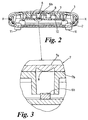
- the window 7 serves to protect the LCD panel 5 from damage and also has a number of lenses 8 moulded into its rear face 7b to focus and guide light from the LEDs 6. This can be seen in figures 2 and 3 of the accompanying drawings.
- Figure 2 shows the hand held unit in cross section along the line X-X.
- a circuit board 10 supports the LEDs 6a, 6b, 6c and 6d spaced below the window on the front panel 3. Only one LED 6b is shown. This can more clearly be seen in figure 3.
- the window 7 above the LED 6b is formed into a lens 8 comprising a convex lens portion which is recessed into the rear face 7b of the window 7. This is slightly larger in diameter than the emitting area of the LED 6.
- the lens 8 focuses and directs the light from the LED 6 through the window towards a user.
- the front panel 3 extends across the area of the LEDs behind the window 7. This acts to support the window and is also formed into a number of small cylindrical openings which help guide the light from the LEDs to the window.
- the circuit board within the unit supports the LEDs, LCD panel and the keypad. It provides the control circuitry for the display and the keypad and interfaces to the motor controller via a lead (not shown) which connects to a D-type connector (also not shown) on the rear of the unit. Feet 11 on the base of the casing 2 allow the keypad to be used on a table or other flat surface as well as in the hand if desired.
Abstract
Description
- This invention relates to improvements in display panels, and in particular to display panels incorporating both a liquid crystal display device (LCD) and at least one light emitting diode (LED).
- With the increase in automation, it is well known to provide an interface between a machine and a user whereby status information can be displayed and/or entered by a user through the interface. A typical interface or display may comprise a display panel incorporating one or more light emitting diodes which are illuminated in dependence upon the status of the machine. For instance, in a very simple display a red light emitting diode can be provided which is illuminated when a fault occurs, or a green light emitting diode may be illuminated to show normal running of the machine.
- For more complex devices, such as motor controllers it is useful to provide a keypad integral with the display to allow the user to input data or perhaps choose from a range of options. In this case, the provision of light emitting diodes may be insufficient to display all the required information in a readily digestible format.
- A more advanced display can be achieved by replacing the light emitting diodes with a liquid crystal display panel capable of displaying alpha-numeric or other graphical information.
- For ease of use, it may be desirable for light emitting diodes to be combined with a liquid crystal display. Due to packing requirements this poses some difficulties. In the past, LCDs and LEDs have been provided separately.
- As will be appreciated, it is usual to mount the LEDs on a circuit board flush with the underside of the front face of the display panel. If an LCD is used this can also be connected to a board through a ribbon cable. A front panel can then be fitted over the board as required.
- To channel light accurately from the LEDs to the front panel, it is known to provide individual optical guides or pipes which direct the light in the required direction. However, the provision of these pipes is costly and difficult to align. Where a number of LEDs are used, assembly time is often prohibitively high.
- In accordance with a first aspect, the invention provides an illuminated display panel comprising a panel portion adapted to be viewed by a user, a liquid crystal display (LCD) panel which is viewable through an opening in the panel portion, a window of transparent material adapted to cover the LCD panel and opening, and at least one light emitting diode (LED) located behind the window, the window incorporating at least one lens which directs light from the light emitting diode through the window so as to be viewed by the user.
- The invention thus provides a display panel which includes both a liquid crystal display and at least one LED where the LED is focused by a respective lens incorporated into the window covering the liquid crystal display.
- Preferably, the window comprises a single piece of plastics material. The window may be of transparent or translucent material. Of course, the material may be tinted. The window may conveniently be produced by a moulding process. This results in low manufacturing costs.
- The lens can be formed integrally with the window by moulding the window with the lens incorporated therein by shaping or contouring the rear face of the window. Of course, the front surface could be shaped instead to define the lens. The lens is preferably formed during the moulding process.
- Preferably, the window is spaced from the LED. The lens ensure sufficient control of light. In the past, it has been necessary to butt the LEDs up to the front panel, making manufacture more complex.
- A mask of substantially opaque material, such as a paint or lacquer, may be applied to part of the rear of the window. This may, for instance block out light from passing through the window other than through an area for viewing information displayed on the liquid crystal display and the LED. The area unmasked for the liquid crystal display may be square or rectangular, and perhaps round for the lens.
- The illuminated display panel can be incorporated into a hand held interface or input device, in which case the panel portion may form the front face (or part thereof) of a hand held casing which includes a numeric or alpha-numeric keypad. The interface device may, in one arrangement, be an input device for a motor controller. The invention may therefore, in a second aspect, comprise an input device for a motor controller incorporating a display panel in accordance with the first aspect of the invention.
- Preferably, the LED is mounted onto a printed circuit board behind the front panel. They may be surface mounted. The liquid crystal display may also be connected to this board either directly or via a short flying lead. The board can be located at least partially behind the panel so that the LED is located directly behind a respective lens formed into the window.
- The shape of the lens formed into the window can be tailored depending on the application. When more than one LED is provided, each lens may have an individual shape, for example, a convex lens shape can be provided which is at least partially recessed into the rear of the window to sharply focus the light from an associated LED. For example, each lens may be formed as a cylindrical bore in the rear of the window with a convex base. Alternatively a concave form could be provided to spread out the light from the LED.
- By forming the lenses into the window, a considerable saving in both time and assembly costs can be achieved. Individual lenses are eliminated and only a single clear element which protects the liquid crystal panel and the LEDs is required. It also enables the LEDs to be located close to the liquid crystal panel.
- The hand held interface device may comprise a first rear casing portion adapted to support a circuit board onto which each LED is mounted, and the front display panel may extend across the rear portion and circuit board like a clam shell to complete the unit. The window can be fixed across the opening in the front of the display panel portion, either flush with, above or below the opening. It may be glued in place or clipped in place. It may be larger than the opening.
- In a most preferred arrangement, the display panel portion may include at least one further opening adjacent the opening for the liquid crystal display. Each additional opening may be associated with a respective LED. This assists in guiding light from the LED to the window. Of course, not all the LEDs need to have an associated opening formed in the front panel and a single opening may co-operate with more than one LED. An advantage of such a construction, however, is that it prevents light from the LEDs leaking away toward other parts of the window or the LED display.
- In an alternative, the portion of the window defining each lens may include an integral cylindrical channel to guide the light from the LEDs. The handheld interface device may include a keypad. This may be mounted on the printed circuit board and extend through one or more openings in the front panel portion.
- The liquid crystal display panel may be adapted to display information input from the keypad and/or supplied to the hand held unit by a remote unit connected to the display unit by a cable.
- There will now be described, by way of example only, one embodiment of the present invention with reference to the accompanying drawings of which:
- Figure 1 is an overview of a hand held display unit in accordance with the invention;
- Figure 2 is a cross-sectional view of the display unit taken along the line X-X in Figure 1; and
- Figure 3 is an enlarged view of a portion of Figure 2.
-
- The display unit 1 is a hand held input device comprising a thin moulded
back casing 2 covered with afront panel portion 3 which incorporates a multi-button keypad, one button of which is labelled 4. The unit also incorporates a liquid crystal display (LCD)panel 5 and four light emitting diodes (LEDs) 6a, 6b, 6c and 6d. The LCD and LEDs are mounted behind awindow 7 on a printedcircuit board 10 between theback casing 2 andfront panel portion 3, and are visible through openings in thefront panel portion 3. - The unit can be connected, for example, to an input to a motor controller through an electrical cable (not shown), and provides a display of the system status and allows the user to input commands to the controller. For example, one LED may be illuminated to indicate that the motor controller is powered up, another to show the motor is running, another to show that an overload condition has been reached, and a final LED to show that the controller has tripped. Indicia (not shown) on the display panel adjacent the LEDs may be used to help the user identify the meaning of the LEDs.
- The
window 7 comprises a clear plastic moulding which has a substantially planarrear face 7b and is convex over at least the portion of itsfront face 7a overlaying theLCD panel 5. This provides a degree of magnification and makes the liquid crystal display easier to read. Thewindow 7 serves to protect theLCD panel 5 from damage and also has a number oflenses 8 moulded into itsrear face 7b to focus and guide light from the LEDs 6. This can be seen in figures 2 and 3 of the accompanying drawings. - Figure 2 shows the hand held unit in cross section along the line X-X. As shown, a
circuit board 10 supports theLEDs front panel 3. Only oneLED 6b is shown. This can more clearly be seen in figure 3. - The
window 7 above theLED 6b is formed into alens 8 comprising a convex lens portion which is recessed into therear face 7b of thewindow 7. This is slightly larger in diameter than the emitting area of the LED 6. Thelens 8 focuses and directs the light from the LED 6 through the window towards a user. It will also be seen that thefront panel 3 extends across the area of the LEDs behind thewindow 7. This acts to support the window and is also formed into a number of small cylindrical openings which help guide the light from the LEDs to the window. - The circuit board within the unit supports the LEDs, LCD panel and the keypad. It provides the control circuitry for the display and the keypad and interfaces to the motor controller via a lead (not shown) which connects to a D-type connector (also not shown) on the rear of the unit.
Feet 11 on the base of thecasing 2 allow the keypad to be used on a table or other flat surface as well as in the hand if desired.
Claims (17)
- An illuminated display panel (1) comprising a panel portion (3) adapted to be viewed by a user, a liquid crystal display (LCD) panel (5) which is viewable through an opening in the panel portion (3), and a window (7) of transparent or translucent material adapted to cover the LCD panel (5) and opening, characterised in that at least one light emitting diode (LED) (6) is located behind the window, the window incorporating at least one lens (8) which directs light from the light emitting diode (6) through the window (7) so as to be viewed by the user.
- An illuminated display panel according to claim 1 characterised in that the window (7) comprises a single piece of plastics material.
- An illuminated display panel (1) according to claim 1 or claim 2 characterised in that the window comprises a tinted material.
- An illuminated display panel (1) according to any preceding claim characterised in that the window (7) is produced by a moulding process and the lens (8) is formed integrally with the window (7) by shaping or contouring the rear face (7b) of the window (7).
- An illuminated display panel (1) according to any preceding claim characterised in that the window (7) is spaced from the LED (6).
- An illuminated display panel according to any preceding claim characterised in that a mask of substantially opaque material, such as a paint or lacquer, is applied to part of the rear (7b) of the window (7).
- An illuminated display panel (1) according to any preceding claim characterised by being adapted to be incorporated into a hand held input device, in which the panel portion (3) forms the front face (or part thereof) of a hand held casing which includes a numeric or alpha-numeric keypad (4).
- An illuminated display panel according to claim 7 characterised in that the LED (6) is mounted onto a printed circuit board (10) behind the front panel (3).
- An illuminated display panel according to claim 8 characterised in that the LED is surface mounted.
- An illuminated display device according to claim 8 or claim 9 characterised in that the liquid crystal display (5) is connected to the board (10) either directly or via a short flying lead.
- An illuminated display device according to claim 8, 9 or 10 characterised in that the board (10) is located at least partially behind the panel (3) so that the LED (6) is located directly behind a respective lens formed into the window.
- An illuminated display device according to any preceding claim characterised in that a plurality of LEDs (6) are provided and each has a corresponding lens (8) formed into the window (7), the shape of each lens (8) formed into the window (7) being tailored individually for each LED (6).
- An illuminated display according to any preceding claim characterised in that the or each lens (8) is formed as a cylindrical bore in the rear of the window (7) with a convex base.
- An illuminated display device according to any preceding claim characterised in that at least the display panel portion (3) includes one further opening adjacent the opening for the liquid crystal display (5) associated with a respective LED (6).
- An input device for a motor controller incorporating a display panel in accordance with any one of claims 1 to 14.
- An input device according to claim 15 adapted to be hand held and comprising a first rear casing portion adapted to support a circuit board (10) onto which each LED (6) is mounted, the front display panel extending across the rear portion and circuit board (10) like a clam shell to complete the unit.
- An input device according to claim 15 or 16 characterised in that the liquid crystal display panel (5) is adapted to display information input from the keypad (4) and/or supplied to the hand held unit by a remote unit connected to the display unit by a cable.
Applications Claiming Priority (2)
| Application Number | Priority Date | Filing Date | Title |
|---|---|---|---|
| GB9826813A GB2344681A (en) | 1998-12-07 | 1998-12-07 | A display panel |
| GB9826813 | 1998-12-07 |
Publications (2)
| Publication Number | Publication Date |
|---|---|
| EP1008977A2 true EP1008977A2 (en) | 2000-06-14 |
| EP1008977A3 EP1008977A3 (en) | 2000-12-06 |
Family
ID=10843732
Family Applications (1)
| Application Number | Title | Priority Date | Filing Date |
|---|---|---|---|
| EP99309833A Withdrawn EP1008977A3 (en) | 1998-12-07 | 1999-12-07 | A display panel |
Country Status (2)
| Country | Link |
|---|---|
| EP (1) | EP1008977A3 (en) |
| GB (1) | GB2344681A (en) |
Cited By (1)
| Publication number | Priority date | Publication date | Assignee | Title |
|---|---|---|---|---|
| CN111261056A (en) * | 2020-02-07 | 2020-06-09 | 山东科技大学 | Switch display device and assembly method thereof |
Citations (6)
| Publication number | Priority date | Publication date | Assignee | Title |
|---|---|---|---|---|
| JPS55113387A (en) * | 1979-02-22 | 1980-09-01 | Sanyo Electric Co Ltd | Light emitting diode indicator |
| US4642627A (en) * | 1984-03-13 | 1987-02-10 | General Electric Company | Illuminated compact control surface |
| US5040868A (en) * | 1989-05-31 | 1991-08-20 | Siemens Aktiengesellschaft | Surface-mountable opto-component |
| DE4013321A1 (en) * | 1990-04-26 | 1991-11-07 | Licentia Gmbh | Indicator operation device for uninterruptable power supply - consists of perforated baseplate and decorative overlay with backlighting by diodes for controlled display of pictogram |
| US5741058A (en) * | 1995-07-31 | 1998-04-21 | Toyoda Gosei Co., Ltd. | LED display device |
| US5841857A (en) * | 1996-11-20 | 1998-11-24 | Harris Corporation | Telephone test set LCD panel carrier |
Family Cites Families (5)
| Publication number | Priority date | Publication date | Assignee | Title |
|---|---|---|---|---|
| CA1038841A (en) * | 1975-11-05 | 1978-09-19 | Northern Electric Company Limited | Light emitting diode indicator assembly for a multiple pushbutton array |
| GB2139392B (en) * | 1983-05-05 | 1986-10-22 | Standard Telephones Cables Ltd | Display device |
| GB8611998D0 (en) * | 1986-05-16 | 1986-06-25 | Husky Computers Ltd | Liquid crystal displays |
| US4899140A (en) * | 1986-09-13 | 1990-02-06 | Minolta Camera Kabushiki Kaisha | Display device for copying machines and the like |
| AT401587B (en) * | 1993-12-30 | 1996-10-25 | Rosenitsch Harald Ing | DISPLAY DEVICE WITH A GRID BODY |
-
1998
- 1998-12-07 GB GB9826813A patent/GB2344681A/en not_active Withdrawn
-
1999
- 1999-12-07 EP EP99309833A patent/EP1008977A3/en not_active Withdrawn
Patent Citations (6)
| Publication number | Priority date | Publication date | Assignee | Title |
|---|---|---|---|---|
| JPS55113387A (en) * | 1979-02-22 | 1980-09-01 | Sanyo Electric Co Ltd | Light emitting diode indicator |
| US4642627A (en) * | 1984-03-13 | 1987-02-10 | General Electric Company | Illuminated compact control surface |
| US5040868A (en) * | 1989-05-31 | 1991-08-20 | Siemens Aktiengesellschaft | Surface-mountable opto-component |
| DE4013321A1 (en) * | 1990-04-26 | 1991-11-07 | Licentia Gmbh | Indicator operation device for uninterruptable power supply - consists of perforated baseplate and decorative overlay with backlighting by diodes for controlled display of pictogram |
| US5741058A (en) * | 1995-07-31 | 1998-04-21 | Toyoda Gosei Co., Ltd. | LED display device |
| US5841857A (en) * | 1996-11-20 | 1998-11-24 | Harris Corporation | Telephone test set LCD panel carrier |
Non-Patent Citations (1)
| Title |
|---|
| PATENT ABSTRACTS OF JAPAN vol. 004, no. 165 (E-034), 15 November 1980 (1980-11-15) & JP 55 113387 A (SANYO ELECTRIC CO LTD;OTHERS: 01), 1 September 1980 (1980-09-01) * |
Cited By (3)
| Publication number | Priority date | Publication date | Assignee | Title |
|---|---|---|---|---|
| CN111261056A (en) * | 2020-02-07 | 2020-06-09 | 山东科技大学 | Switch display device and assembly method thereof |
| WO2021155621A1 (en) * | 2020-02-07 | 2021-08-12 | 山东科技大学 | Switch display apparatus and assembling method therefor |
| US11333318B2 (en) | 2020-02-07 | 2022-05-17 | Shandong University Of Science And Technology | Switch display apparatus and assembling method thereof |
Also Published As
| Publication number | Publication date |
|---|---|
| GB2344681A (en) | 2000-06-14 |
| GB9826813D0 (en) | 1999-01-27 |
| EP1008977A3 (en) | 2000-12-06 |
Similar Documents
| Publication | Publication Date | Title |
|---|---|---|
| US6011961A (en) | Keypad apparatus with integral display indicators | |
| US7283066B2 (en) | Illuminated keyboard | |
| US6200010B1 (en) | Display arrangement for a motor vehicle | |
| US4768300A (en) | Illuminated information display | |
| JP2022068151A (en) | Assembly for forming part of electronic device, electronic device, and method for manufacturing cover structure assembly for electronic device | |
| US5134505A (en) | Push-button switch with liquid-crystal display | |
| US20050083672A1 (en) | Illuminated keyboard | |
| EP1319553B1 (en) | Vehicle instrument | |
| US5892192A (en) | Operation device for vehicle air conditioner | |
| US20080310141A1 (en) | Vehicle instrument cluster | |
| US6727962B2 (en) | Combination instrument for a motor vehicle | |
| EP3045342A1 (en) | Reconfigurable gauge over display | |
| US20050093721A1 (en) | Illuminated keyboard | |
| US20050068202A1 (en) | Illuminated keyboard | |
| JP2003260924A (en) | Indicator structure | |
| EP1008977A2 (en) | A display panel | |
| US20110226595A1 (en) | Illumination type key sheet and push button switch | |
| CN110099149B (en) | Panel assembly, display module and electronic device | |
| US20030107550A1 (en) | Display device with at least one pointer instrument arranged in its housing part on the front side | |
| US20120087149A1 (en) | Ultra-thin light guide for cluster gauge illumination over display structures | |
| US20220345129A1 (en) | Electronic control device | |
| JP2007085935A (en) | Display for vehicle | |
| EP1312974B3 (en) | Electronic Display Device and Lighting Control Method of Same | |
| US20070176853A1 (en) | Control panel device and display | |
| GB2448867A (en) | Backlit display |
Legal Events
| Date | Code | Title | Description |
|---|---|---|---|
| PUAI | Public reference made under article 153(3) epc to a published international application that has entered the european phase |
Free format text: ORIGINAL CODE: 0009012 |
|
| AK | Designated contracting states |
Kind code of ref document: A2 Designated state(s): DE FR GB |
|
| AX | Request for extension of the european patent |
Free format text: AL;LT;LV;MK;RO;SI |
|
| PUAL | Search report despatched |
Free format text: ORIGINAL CODE: 0009013 |
|
| AK | Designated contracting states |
Kind code of ref document: A3 Designated state(s): AT BE CH CY DE DK ES FI FR GB GR IE IT LI LU MC NL PT SE |
|
| AX | Request for extension of the european patent |
Free format text: AL;LT;LV;MK;RO;SI |
|
| STAA | Information on the status of an ep patent application or granted ep patent |
Free format text: STATUS: THE APPLICATION HAS BEEN WITHDRAWN |
|
| AKX | Designation fees paid |
Free format text: DE FR GB |
|
| 18W | Application withdrawn |
Withdrawal date: 20010725 |