EP1008865A2 - Strahlungsabbildungsdetektor - Google Patents
Strahlungsabbildungsdetektor Download PDFInfo
- Publication number
- EP1008865A2 EP1008865A2 EP99309824A EP99309824A EP1008865A2 EP 1008865 A2 EP1008865 A2 EP 1008865A2 EP 99309824 A EP99309824 A EP 99309824A EP 99309824 A EP99309824 A EP 99309824A EP 1008865 A2 EP1008865 A2 EP 1008865A2
- Authority
- EP
- European Patent Office
- Prior art keywords
- detector
- radiation
- segments
- view
- transverse dimension
- Prior art date
- Legal status (The legal status is an assumption and is not a legal conclusion. Google has not performed a legal analysis and makes no representation as to the accuracy of the status listed.)
- Granted
Links
- 230000005855 radiation Effects 0.000 title claims abstract description 62
- 238000003384 imaging method Methods 0.000 title description 13
- 238000000034 method Methods 0.000 claims description 18
- 230000035945 sensitivity Effects 0.000 claims description 15
- 229910003460 diamond Inorganic materials 0.000 claims description 2
- 239000010432 diamond Substances 0.000 claims description 2
- 239000004065 semiconductor Substances 0.000 abstract description 5
- 239000000463 material Substances 0.000 description 17
- 230000033001 locomotion Effects 0.000 description 7
- MARUHZGHZWCEQU-UHFFFAOYSA-N 5-phenyl-2h-tetrazole Chemical compound C1=CC=CC=C1C1=NNN=N1 MARUHZGHZWCEQU-UHFFFAOYSA-N 0.000 description 6
- 230000008901 benefit Effects 0.000 description 5
- QWUZMTJBRUASOW-UHFFFAOYSA-N cadmium tellanylidenezinc Chemical compound [Zn].[Cd].[Te] QWUZMTJBRUASOW-UHFFFAOYSA-N 0.000 description 5
- XQPRBTXUXXVTKB-UHFFFAOYSA-M caesium iodide Chemical compound [I-].[Cs+] XQPRBTXUXXVTKB-UHFFFAOYSA-M 0.000 description 5
- 239000004020 conductor Substances 0.000 description 5
- 239000013078 crystal Substances 0.000 description 5
- 229910052732 germanium Inorganic materials 0.000 description 5
- GNPVGFCGXDBREM-UHFFFAOYSA-N germanium atom Chemical compound [Ge] GNPVGFCGXDBREM-UHFFFAOYSA-N 0.000 description 5
- 238000012633 nuclear imaging Methods 0.000 description 4
- WFKWXMTUELFFGS-UHFFFAOYSA-N tungsten Chemical compound [W] WFKWXMTUELFFGS-UHFFFAOYSA-N 0.000 description 4
- 229910052721 tungsten Inorganic materials 0.000 description 4
- 239000010937 tungsten Substances 0.000 description 4
- 230000003750 conditioning effect Effects 0.000 description 3
- 230000000694 effects Effects 0.000 description 3
- 238000013519 translation Methods 0.000 description 3
- 229920000134 Metallised film Polymers 0.000 description 2
- 230000004075 alteration Effects 0.000 description 2
- 238000013459 approach Methods 0.000 description 2
- 230000005540 biological transmission Effects 0.000 description 2
- 238000004891 communication Methods 0.000 description 2
- 238000001514 detection method Methods 0.000 description 2
- BEQZMQXCOWIHRY-UHFFFAOYSA-H dibismuth;trisulfate Chemical compound [Bi+3].[Bi+3].[O-]S([O-])(=O)=O.[O-]S([O-])(=O)=O.[O-]S([O-])(=O)=O BEQZMQXCOWIHRY-UHFFFAOYSA-H 0.000 description 2
- 238000012986 modification Methods 0.000 description 2
- 230000004048 modification Effects 0.000 description 2
- 230000003287 optical effect Effects 0.000 description 2
- 230000008569 process Effects 0.000 description 2
- ZCXUVYAZINUVJD-AHXZWLDOSA-N 2-deoxy-2-((18)F)fluoro-alpha-D-glucose Chemical compound OC[C@H]1O[C@H](O)[C@H]([18F])[C@@H](O)[C@@H]1O ZCXUVYAZINUVJD-AHXZWLDOSA-N 0.000 description 1
- 229910017115 AlSb Inorganic materials 0.000 description 1
- JBRZTFJDHDCESZ-UHFFFAOYSA-N AsGa Chemical compound [As]#[Ga] JBRZTFJDHDCESZ-UHFFFAOYSA-N 0.000 description 1
- 241001581440 Astroides Species 0.000 description 1
- RYGMFSIKBFXOCR-UHFFFAOYSA-N Copper Chemical compound [Cu] RYGMFSIKBFXOCR-UHFFFAOYSA-N 0.000 description 1
- 229910005543 GaSe Inorganic materials 0.000 description 1
- -1 Hgl2 Chemical compound 0.000 description 1
- XUIMIQQOPSSXEZ-UHFFFAOYSA-N Silicon Chemical compound [Si] XUIMIQQOPSSXEZ-UHFFFAOYSA-N 0.000 description 1
- 229910000831 Steel Inorganic materials 0.000 description 1
- 230000002745 absorbent Effects 0.000 description 1
- 239000002250 absorbent Substances 0.000 description 1
- 239000000853 adhesive Substances 0.000 description 1
- 230000001070 adhesive effect Effects 0.000 description 1
- 238000004458 analytical method Methods 0.000 description 1
- 210000003484 anatomy Anatomy 0.000 description 1
- UHYPYGJEEGLRJD-UHFFFAOYSA-N cadmium(2+);selenium(2-) Chemical compound [Se-2].[Cd+2] UHYPYGJEEGLRJD-UHFFFAOYSA-N 0.000 description 1
- 238000004364 calculation method Methods 0.000 description 1
- 238000006243 chemical reaction Methods 0.000 description 1
- 229910052802 copper Inorganic materials 0.000 description 1
- 239000010949 copper Substances 0.000 description 1
- 238000012937 correction Methods 0.000 description 1
- 230000003247 decreasing effect Effects 0.000 description 1
- 230000001419 dependent effect Effects 0.000 description 1
- 238000011161 development Methods 0.000 description 1
- 230000018109 developmental process Effects 0.000 description 1
- 238000002059 diagnostic imaging Methods 0.000 description 1
- 238000006073 displacement reaction Methods 0.000 description 1
- 239000000835 fiber Substances 0.000 description 1
- 230000006870 function Effects 0.000 description 1
- 238000011835 investigation Methods 0.000 description 1
- 238000004519 manufacturing process Methods 0.000 description 1
- 230000007246 mechanism Effects 0.000 description 1
- 210000000056 organ Anatomy 0.000 description 1
- 239000002985 plastic film Substances 0.000 description 1
- 238000002600 positron emission tomography Methods 0.000 description 1
- 238000012545 processing Methods 0.000 description 1
- 239000012217 radiopharmaceutical Substances 0.000 description 1
- 229940121896 radiopharmaceutical Drugs 0.000 description 1
- 230000002799 radiopharmaceutical effect Effects 0.000 description 1
- 230000004044 response Effects 0.000 description 1
- 239000011163 secondary particle Substances 0.000 description 1
- 230000011218 segmentation Effects 0.000 description 1
- 229910052710 silicon Inorganic materials 0.000 description 1
- 239000010703 silicon Substances 0.000 description 1
- 238000002603 single-photon emission computed tomography Methods 0.000 description 1
- FVAUCKIRQBBSSJ-UHFFFAOYSA-M sodium iodide Chemical compound [Na+].[I-] FVAUCKIRQBBSSJ-UHFFFAOYSA-M 0.000 description 1
- 239000010959 steel Substances 0.000 description 1
Images


Classifications
-
- G—PHYSICS
- G01—MEASURING; TESTING
- G01T—MEASUREMENT OF NUCLEAR OR X-RADIATION
- G01T1/00—Measuring X-radiation, gamma radiation, corpuscular radiation, or cosmic radiation
- G01T1/16—Measuring radiation intensity
- G01T1/161—Applications in the field of nuclear medicine, e.g. in vivo counting
- G01T1/164—Scintigraphy
- G01T1/1641—Static instruments for imaging the distribution of radioactivity in one or two dimensions using one or several scintillating elements; Radio-isotope cameras
- G01T1/1648—Ancillary equipment for scintillation cameras, e.g. reference markers, devices for removing motion artifacts, calibration devices
Definitions
- the present invention relates to the field of detectors for imaging.
- the invention finds particular application in conjunction with nuclear or gamma cameras and single photon emission computed tomography (SPECT) and will be described with particular reference thereto. It is to be appreciated, however, that the present invention will also find application in other non-invasive investigation techniques and imaging systems such as single photon planar imaging, whole body nuclear scans, positron emission tomography (PET) and other diagnostic modes.
- SPECT single photon emission computed tomography
- one or more radiation detectors are mounted on a movable gantry to view an examination region which receives a subject therein.
- one or more radiopharmaceuticals or radioisotopes such as 99m Tc or 18 F-Fluorodeoxyglucose (FDG) capable of generating emission radiation are introduced into the subject.
- the radioisotope preferably travels to an organ of interest whose image is to be produced.
- the detectors scan the subject along a selected path or scanning trajectory and radiation events are detected on each detector.
- the detector includes a scintillation crystal that is viewed by an array of photomultiplier tubes.
- a collimator which includes a grid- or honeycomb-like array of radiation absorbent material is located between the scintillation crystal and limits the angle of acceptance of radiation which will be received by the scintillation crystal.
- the relative outputs of the photomultiplier tubes are processed and corrected to generate an output signal indicative of the position and energy of the detected radiation.
- the radiation data is then reconstructed into an image representation of a region of interest.
- ROLEC rotating laminar radionuclide camera
- CdTe cadmium telluride
- Mauderli, et al. A Computerized Rotating Laminar Radionuclide Camera , J. Nucl. Med 20: 341-344 (1979) and Entine, et al., Cadmium Telluride Gamma Camera, IEEE Transactions on Nuclear Science, Vol. NS-26, No. 1: 552-558 (1979).
- the device included a linear array of CdTe detectors separated by tungsten plates that confined the field of view of each detector to one dimension.
- the device had a square (approximately 4 cm x 4 cm) active area, although a circular lead mask reduced the active area to 13.2 cm 2 .
- the detectors, which had platinum-film electrodes were attached to copper strips on a printed circuit board that also served as the base of the collimator and as a support for amplifier-discriminator circuits.
- a ROLEC having a 250 mm x 250 mm active area was disclosed in Tosswill, U.S. Patent No. 4,090,080.
- the device included scintillating plastic sheets disposed between parallel collimator plates supported by a steel frame. Fibre optics epoxied to the rear surface of each scintillating sheet transferred light generated in the each of the detectors to a corresponding photomultiplier.
- the ROLEC may be rotated discontinuously or continuously, or operated moving its axis along another curved or other configuration or without rotation, with symmetry preferred but not essential.
- a 11.5 mm thick, 45 mm x 45 mm segmented germanium detector was placed behind parallel tungsten plates.
- the crystal was segmented to form a plurality of channels, with the plates aligned with the segmentations.
- a 4.5 cm diameter viewing aperture was located between the detector and the activity source. Projection data acquired at multiple angular orientations as the detector-collimator assembly was rotated about its centre was mathematically reconstructed to form a two-dimensional image of the activity distribution.
- a second version simulated a 195 mm x 195 mm detection area.
- Five germanium blocks having a total length of 250 mm segmented into distinct electrical channels.
- the detector was translated linearly in a direction perpendicular to the plane of the plates to simulate a full-size detector.
- ROLECs are their high efficiency relative to traditional Anger cameras.
- the structure of the collimator permits a greater percentage of incident radiation to reach the surface of the detector.
- Spatial resolution may be improved by increasing the height of the collimator or reducing the distance between the collimator elements with less effect on efficiency as compared to traditional cameras.
- ROLECs have the advantage of relatively higher efficiency and spatial resolution, they have been expensive to produce inasmuch as significant quantities of relatively expensive detector material have been required. Although detector material cost can be reduced by using a number of relatively smaller detector segments, such an approach complicates the manufacturing process and requires that variations in the response of the individual segments be considered.
- Still another drawback is that the collimator slat length has been equal to the detector field of view. This has required additional detector, collimator, and structural material, has introduced spurious counts which do not contribute to useful image information, and has introduced additional mass and bulk into a rotating structure.
- a radiation detection apparatus includes a detector.
- the detector includes a plurality of longitudinally-spaced radiation attenuative septa which define a plurality of slits. Each slit has a longitudinal and a transverse dimension, the transverse dimension being greater than the longitudinal dimension.
- the detector also includes a plurality of detector segments, each detector segment having a transverse dimension and detecting radiation received in a corresponding slit.
- the apparatus also includes a drive operatively connected to one of the detector and the object so as to vary the angular relationship between the slits and the object. The transverse dimensions of the detector segments are less than the longitudinal field of view of the detector.
- a detector segment includes two or more sub-segments.
- the sum of the transverse dimensions of the sub-segments is less than the longitudinal field of view.
- the detector includes first and second radiation attenuative side shields.
- the aperture aspect ratio of the detector is greater than one.
- the transverse dimension of each detector segment is less than the transverse dimension of the corresponding slit.
- each detector segment includes at least two detector sub-segments.
- the sum of the transverse dimensions of the sub-segments is less than the transverse dimension of the slit.
- radiation attenuative members are disposed between detector segments which detect radiation received in adjacent slits.
- the thickness of the radiation attenuative material portion may be less than the thickness of the septum.
- the septa may include a material free region adapted to receive the radiation attenuative members.
- an electrical conductor in electrical contact with a detector segment is disposed between the radiation attenuative member and the detector segment.
- the detector segments are physically discrete.
- a cross section of the detector segments is one of round and rectangular.
- the apparatus includes a reconstruction processor operatively connected to the detector segments for generating an image indicative of radiation received by the detector segments.
- the apparatus includes means for supporting the detector in relation to an object being imaged.
- an apparatus includes a detector which includes a collimator having a plurality of longitudinally spaced radiation attenuative elements which define a plurality of longitudinally spaced apertures each having transverse dimension greater than it longitudinal dimension.
- the collimator is movable during the examination so as to vary the angular relationship between the apertures and the object.
- the detector also includes a plurality of radiation sensitive detector segments each having a transverse dimension and detecting radiation received in a corresponding aperture.
- the aperture aspect ratio of the detector is greater than one.
- the apparatus also includes a reconstruction processor operatively connected to the detector segments for generating an image indicative of radiation received by the detector segments.
- the detector segments include a semiconductor.
- the semiconductor material may be cadmium zinc telluride.
- the detector segments include a scintillating material and a photodetector in optical communication with the scintillating material.
- the scintillating material is cesium iodide.
- a rotating laminar emission camera has an aspect ratio greater than one.
- an apparatus for detecting radiation indicative of an object includes a detector having a plurality of septa.
- the detector also includes a plurality of radiation attenuative members. Detector segments which detect radiation received in adjacent slits have a radiation attenuative member interposed therebetween.
- the septa and the radiation attenuative members comprise tungsten.
- the septa and the radiation attenuative members are mounted for transverse movement relative to the septa.
- a method includes using a detector to detect gamma radiation indicative of radionuclide decays, rotating the detector in a plane, and in coordination with the rotation of the detector, translating the detector so that the sensitivity of the detector is substantially constant over a non-circular field of view.
- the non-circular field of view may be a square.
- the detector is translated in coordination with its rotation so that a line segment perpendicular to the longitudinal axis traces the path traveled by the centroid of a curve of constant width rotating within the square.
- the curve of constant width may be a Reuleaux triangle.
- an object being imaged such as a patient is supported on a support A.
- the support includes a thin, relatively radiation transmissive support surface 10 which is mounted cantilevered from a base 12.
- the base includes motors for raising and lowering the support surface and for extending and retracting the support surface in a longitudinal direction relative to a nuclear camera gantry B. Alternately, relative longitudinal motion may be achieved by moving the gantry B in the longitudinal direction.
- the gantry B includes stationary 18 and rotating 30 gantry portions.
- Detectors 22a, 22b, 22c are mounted to the rotating gantry portion 30 and define an aperture into which the anatomy of a patient may be inserted.
- Each detector 22 includes an enclosure comprised of a radiation attenuative material such as lead.
- the detectors are mounted to the gantry 30 so as to be rotatable about an axis of rotation 70, radially toward and away from the imaging region, and tangentially with respect to the imaging region. The relative angular positions of the detectors about the examination region may also be varied.
- the rotating detectors define a generally circular imaging region, the precise shape of which may vary if the detectors are moved radially during rotation of the gantry 30.
- radiation data is collected as the detectors are rotated about the imaging region, with the data used to generate an image indicative of the detected radionuclide decays.
- the detector has been described as having three detectors 22, greater (e.g., four or more) or fewer (e.g., 1 or 2) numbers of detectors may be used. It is not necessary that the detectors be disposed at equal angular intervals about the examination region; a variety of different configurations may be implemented. It is also not necessary that the detectors be moved with respect to or rotated about the patient; relative motion may be provided by moving the patient with respect to the detectors.
- the gantry shown in Figure 1 is exemplary of a gantry which provides a number of degrees of freedom.
- Other suitable detector and patient supports may be implemented, provided that the desired relative motion (if any) between the detector(s) and the patient or between the detectors themselves is provided.
- each detector includes a rotating detector portion 23.
- Signals from the detector elements 106a, 106b, ... 106n of each detector are received by signal conditioning and analog to digital conversion circuitry 130 and stored in memory 132.
- a motor drive 134 drives a motor 136 which causes the rotating portion 23 to rotate about an axis of rotation 109 perpendicular to a major plane of the rotating portion.
- a signal 138 indicative of the rotational position of the rotating portion is provided to memory 132 and the data from the detector elements 106 stored accordingly.
- a reconstruction processor 140 reconstructs the data for display in human readable form on a display device 142 such as a monitor, film, or the like.
- tomographic images for example a plurality of axial slices, may be generated.
- the data may be reconstructed using a two step process.
- the data received by the detector elements 106 at each of a plurality of positions about the axis of rotation 109 is reconstructured to create a two-dimensional data set analogous to the data generated by a conventional two dimensional detector.
- Two dimensional data sets obtained at a plurality of positions about the axis of rotation 70 may in turn be reconstructed so as to create volumetric image data.
- the data may be reconstructed using a single step process whereby the data received by the detector elements 106 at each of a plurality of positions about the axis of rotation 109 and the axis of rotation 70 are reconstructed directly to form the volumetric image data.
- the rotating detector portion 23 includes a collimator having a plurality of rectangular, parallel spaced apart septa or slats 102a, 102b, ... 102n.
- the septa are constructed from a radiation attenuative material.
- the septa are fabricated from tungsten, although other materials providing suitable attenuation may be used.
- the spacing between the septa defines a plurality of slits 104a, 104b, ... 104n having a width G.
- Each septum has a height Wz, a transverse dimension Wy, and a thickness Wx.
- a front edge 107 of the septa faces the examination region.
- the longitudinal field of view 110 corresponds to the number of septa multiplied by their spacing.
- a radiation sensitive detector element 106a, 106b, ... 106n is disposed so as to detect radiation received in each of the slits 104a, 104b, ... 104n.
- Each of the detectors 106a, 106b, ... 106n has a transverse dimension Cy, a thickness Cx, and a height Cz The detectors are centred about the midpoint of the transverse dimension Wy of the septa 102, although they may be offset therefrom.
- the detector elements are fabricated from scintillating materials such as cesium iodide (CsI) or sodium iodide (NaI) in optical communication with a photo diode or other appropriate photodetector.
- CsI cesium iodide
- NaI sodium iodide
- a semiconductor detector material such as cadmium zinc telluride (CdZnTe) may also be used.
- CdZnTe cadmium zinc telluride
- other materials such as silicon (Si), germanium (Ge), cadmium telluride (CdTe) , Hgl 2 , gallium arsenide (GaAs), bismuth sulphate (Bi 2 S 3 ), Pbl 2 , GaSe, AlSb, or CdSe may also be used.
- the rotating detector portion 23 is rotatable about an axis of rotation 109 perpendicular to its major plane.
- the detector may be rotated continuously as radiation data is collected. Alternately, data may be collected with the detector located at a plurality of discrete angular positions.
- Figure 4 depicts a side view of a detector wherein, for ease of illustration, the transverse dimension Cy and height Cz of the detector elements 106 are zero.
- Lead side shields 101 extend along the sides of the detector.
- the detector is typically operated with the front 107 of the septa at a height H above an imaging plane 112.
- the corner projections 114 of the septa 102 intersect the imaging plane 112 to define a transverse field view therein.
- the aperture aspect ratio is preferably selected so that the transverse field of view is equal to the LFOV 110 of the detector 23, the dimension 110 from Figure 3 shown on Figure 4 for reference.
- the sensitivity of the detector is approximately linearly related to the perimeter C y + 2C z of the detector elements 106. Hence, sensitivity may be improved by increasing the perimeter of the detector elements. With reference to Equation 2 and Figure 5A, however, increasing the perimeter affects the aspect ratio as well as counts received from outside the useful field of view and the cost of the detector elements 106. As illustrated, the detector aspect ratio (LFOV/Cy) is greater than 1 as well as greater than the aperture aspect ratio. Some or all of the slat 102 material in the regions 115 outside the corner projections 114 may also be eliminated. Hence, the septa may have a trapezoidal or other non-rectangular shape.
- the aspect ratio described in Equation 2 provides substantially uniform sensitivity across the field of view.
- An extended field of view is defined by the intersection of the corner projections 111 and the image plane, albeit with reduced sensitivity in the extended field of view portions 113a, 113b. Calculation of the aperture aspect ratio may be adjusted accordingly.
- the number of detector elements 106 may be varied to provide a desired sensitivity and sensitivity profile.
- two detector elements having a circular cross section are used.
- three rectangular detector elements are provided.
- the detector element is offset from the transverse centre of the septa.
- the desired aspect ratios may be determined based on the detector element 106 and slat 102 geometries as described above.
- Electrical connections to the detector elements 106 may be made by placing a conductor such as aluminized mylar between the detector elements 106 and the septa 102.
- a conductor such as aluminized mylar
- One drawback to this approach is that the thickness of the conductive material introduces a dead space between the septa and the detector elements, which deleteriously affects sensitivity. Grooves or depressions in the septa 102 or in the detector elements 106 may be used to account for some or all of the thickness of the conductor.
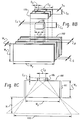
- FIG. 6 an alternate configuration which facilitates electrical connections to the detector elements 106 is shown.
- the detector elements 106 are located between the septa 102 with their rear surfaces extending beyond the rear surface of the septa 102 so as to permit access to the side surfaces of the detector elements 106.
- Lead wires 116 are connected to the detector elements 106 using conventional bonding techniques.
- the lead wires 116 are in turn connected to circuit boards 114 which carry signal conditioning electronics.
- each of the collimator elements 102 may include a notched region 118.
- the detector elements 106 are interleaved with corresponding collimator segments 120 to form a detector subassembly 122.
- the detector elements 106 are adhered to the corresponding collimator segments 120 using an adhesive. Alternately, a mechanical frame arrangement may be used.
- the collimator assembly 100 and the detector subassembly 120 are assembled separately and subsequently joined.
- the notched region in the collimator elements 102 may be eliminated with the detector elements 106 and collimator segments or separators 120 mounted therebehind.
- the transverse dimension of the collimator segments 120 is preferably greater than or equal to the transverse dimension of the detector elements 106. More particularly, the collimator segments 120 are preferably sized so that their corner projections are at least coextensive with those of the slats.
- a particular advantage to such an arrangement is that the detector element 106 collimator segment arrangement may be fixedly or movably mounted to the collimator elements 102 in any number of positions.
- Figure 8B depicts the arrangement of Figure 8A in exploded view.
- the LFOV of the detector is defined by N x P (N detector elements at a pitch P).
- the dimensions of the detector elements 106 are influenced a number of factors.
- the energy resolution, sensitivity, cost, and secondary particle leakage are all influenced by dimension Cx, Cy, and Cz of the detector elements.
- Cx dimension
- Cy dimension
- Cz dimension
- the ratio G/Wz is selected to provide a desired spatial resolution.
- Slat thickness Wx is selected to maximize sensitivity while minimizing punch through and providing suitable mechanical stability.
- the thickness t s of the separators or collimator segments 120 may be less than that of the septa 102.
- Aluminized mylar or other suitable conductive material may be then placed between the detector elements 106 and the collimator segments 120 to provide the necessary electrical interconnections.
- the rear surfaces of the detector elements 106 may extend beyond the rear surfaces of the collimator segments 120 to facilitate electrical connections as described above.
- the height Sz of the separators is preferably greater than or equal to the height Cz of the detector elements.
- the length Sy of the separators 120 is greater than or equal to the length Cy of the detector elements.
- the various parameters may be selected to be as follows (dimensions in mm): Parameter CdZnTe Detector CsI Detector N 128 128 Cx 1.5 1.5 Cy 12 30 Cz 8 2 Wx 0.3 0.3 Wy 130 130 Wz 46 46 Sx ⁇ 0.3 ⁇ 0.3 Sy 37 37 Sz 8 2 P 1.8 1.8 G 1.5 1.5 Dy 8.3 2 H 50 50
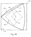
- Rotating the detector 23 about the axis of rotation 109 provides a circular field of view.
- the relative angular relationship between the slits and the object being examined may also be varied in coordination with translation of the detector.
- the detector may be moved along a curve of constant width 200 in coordination with rotation so as to maximize coverage of a field of view 202.
- the field of view 202 is a square.
- curve of constant width describes a family of figures that, at any orientation within the square, will touch all four sides of the square.
- the curve of constant width 200 orbits within the square 202, its centroid likewise traces an orbit 204.
- the curve of constant width 200 is a Reuleaux triangle.
- a Reuleaux triangle includes three circular arc segments, the endpoints of which intersect the vertices of an equilateral triangle.
- the rotating detector portion 23 may be visualized as forming one of the sides of the equilateral triangle, i.e. with its longitudinal axis intersecting two vertices of the Reuleaux triangle.
- a circle is a curve of constant width, albeit one whose centroid does not translate as the circle is rotated within the square.
- the detector segments may be centred about the transverse extent of the septa. In a preferred embodiment, however, the detectors are offset from the centre toward a side of the detector nearer the outside of the square by an amount equal to one fourth the transverse extent of the septa. Alternately, the longitudinal axis may be offset from the transverse centre of the detector 23.
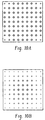
- a particular advantage of this technique is that substantially uniform sensitivity over the square field of view is provided as compared to rotational orbit of the same detector without translation, as depicted in Figures 10A and 10B, respectively.
- a smaller detector may be used to provide a desired square field of view.
- the same sized detector may be used to provide a larger field of view than with rotation alone, albeit with less uniform sensitivity.
- Another advantage of the technique is that the centre of the detector does not always point to the same location in the reconstruction field. Because there is no fixed point in the motion of the detector, there is no special point in the reconstruction field.
- a suitable drive arrangement is used to drive the detector 23 through its orbit.
- an x-y positioning drive for causing the requisite translational motion together with a rotating drive for causing the requisite coordinated rotation may be used.
- a geared drive mechanism which engages both ends of the detector 23 and causes them to travel along the path may be implemented to provide coordinated translational and rotational motion.
- the disclosed orbit technique may also be used in transmission radionuclide imaging, for example for attenuation correction.
- a line or generally rectangular sheet source may be moved in the orbit described above, with the object being imaged located between the transmission source and a suitable detector, for example a detector following a coordinated Reuleaux orbit or a conventional gamma camera detector.
- the technique is not limited to medical imaging. It may be used where it is necessary to collect other types of position dependent information. Thus, the technique may be used, together with suitable detectors or receivers to detect other types of radiation such as infrared, visible, infrared or other light, thermal radiation, electrical and magnetic fields, and the like. Similarly, the technique may be used, together with suitable emitters or transmitters, in connection with sources of other types of radiation, including those set forth above.
Landscapes
- Physics & Mathematics (AREA)
- Health & Medical Sciences (AREA)
- Life Sciences & Earth Sciences (AREA)
- General Physics & Mathematics (AREA)
- General Health & Medical Sciences (AREA)
- Medical Informatics (AREA)
- Nuclear Medicine, Radiotherapy & Molecular Imaging (AREA)
- Optics & Photonics (AREA)
- Engineering & Computer Science (AREA)
- Biomedical Technology (AREA)
- High Energy & Nuclear Physics (AREA)
- Molecular Biology (AREA)
- Spectroscopy & Molecular Physics (AREA)
- Measurement Of Radiation (AREA)
- Nuclear Medicine (AREA)
- Analysing Materials By The Use Of Radiation (AREA)
- Apparatus For Radiation Diagnosis (AREA)
Applications Claiming Priority (2)
| Application Number | Priority Date | Filing Date | Title |
|---|---|---|---|
| US206508 | 1998-12-07 | ||
| US09/206,508 US6359279B1 (en) | 1998-12-07 | 1998-12-07 | Detector for nuclear imaging |
Publications (3)
| Publication Number | Publication Date |
|---|---|
| EP1008865A2 true EP1008865A2 (de) | 2000-06-14 |
| EP1008865A3 EP1008865A3 (de) | 2003-03-05 |
| EP1008865B1 EP1008865B1 (de) | 2007-10-31 |
Family
ID=22766716
Family Applications (1)
| Application Number | Title | Priority Date | Filing Date |
|---|---|---|---|
| EP99309824A Expired - Lifetime EP1008865B1 (de) | 1998-12-07 | 1999-12-07 | Strahlungsabbildungsdetektor |
Country Status (5)
| Country | Link |
|---|---|
| US (2) | US6359279B1 (de) |
| EP (1) | EP1008865B1 (de) |
| JP (1) | JP2000180549A (de) |
| AT (1) | ATE377201T1 (de) |
| DE (1) | DE69937437T2 (de) |
Cited By (3)
| Publication number | Priority date | Publication date | Assignee | Title |
|---|---|---|---|---|
| WO2002039142A2 (en) * | 2000-11-08 | 2002-05-16 | Koninklijke Philips Electronics N.V. | Correction for depth-depending sensitivity in rotating slat-collimated gamma camera |
| WO2002075357A1 (en) | 2001-03-15 | 2002-09-26 | Koninklijke Philips Electronics Nv | Focused rotating slat-hole for gamma cameras |
| WO2004061477A1 (en) * | 2003-01-06 | 2004-07-22 | Koninklijke Philips Electronics N.V. | Constant radius single photon emission tomography |
Families Citing this family (22)
| Publication number | Priority date | Publication date | Assignee | Title |
|---|---|---|---|---|
| US6359279B1 (en) * | 1998-12-07 | 2002-03-19 | Picker International, Inc. | Detector for nuclear imaging |
| US7015476B2 (en) * | 1999-04-14 | 2006-03-21 | Juni Jack E | Single photon emission computed tomography system |
| US7105825B2 (en) * | 1999-04-14 | 2006-09-12 | Juni Jack E | Single photon emission computed tomography system |
| US7767972B2 (en) * | 1999-04-14 | 2010-08-03 | Juni Jack E | Single photon emission computed tomography system |
| US6787777B1 (en) * | 2000-11-09 | 2004-09-07 | Koninklijke Philips Electronics, N.V. | Nuclear imaging system and method using segmented field of view |
| US20020147847A1 (en) * | 2001-04-09 | 2002-10-10 | Sun Microsystems, Inc. | System and method for remotely collecting and displaying data |
| US6728583B2 (en) * | 2001-06-27 | 2004-04-27 | Koninklijke Philips Electronics N.V. | User interface for a gamma camera which acquires multiple simultaneous data sets |
| US20030226971A1 (en) * | 2002-06-11 | 2003-12-11 | Chandross Edwin Arthur | Nuclear radiation detector |
| US6881959B2 (en) * | 2002-10-31 | 2005-04-19 | The Regents Of The University Of Michigan | Method and system for generating an image of the radiation density of a source of photons located in an object |
| DE102004001688B4 (de) * | 2004-01-12 | 2010-01-07 | Siemens Ag | Detektormodul |
| US7235790B2 (en) * | 2004-02-17 | 2007-06-26 | Ge Medical Systems Global Technology Company, Llc | Methods and apparatus for radiation detection |
| US7147445B2 (en) * | 2004-03-02 | 2006-12-12 | Krayer William L | Turntable with turning guide |
| US7137797B2 (en) | 2004-03-02 | 2006-11-21 | Krayer William L | Turntable with gerotor |
| US7310407B2 (en) * | 2004-09-03 | 2007-12-18 | Juni Jack E | Nuclear medical imaging device |
| US7378661B2 (en) * | 2005-10-11 | 2008-05-27 | Siemens Medical Solutions Usa, Inc. | Asymmetrical positron emission tomograph detectors |
| US7831024B2 (en) * | 2006-03-17 | 2010-11-09 | The Trustees Of The University Of Pennsylvania | Slit-slat collimation |
| US7388207B1 (en) | 2006-03-28 | 2008-06-17 | University Of Utah Research Foundation | Skew slit collimator and method of use thereof |
| DE102008063310B3 (de) * | 2008-12-30 | 2010-04-15 | Siemens Aktiengesellschaft | Verfahren zur Herstellung eines Strahlungsdetektormoduls, Strahlungsdetektormodul, Verfahren zur Herstellung eines Strahlungsdetektors und Strahlungsdetektor |
| US20120175509A1 (en) * | 2011-01-11 | 2012-07-12 | General Electric Company | Gamma camera calibration methods and systems |
| US9207333B2 (en) | 2011-04-21 | 2015-12-08 | Kabushiki Kaisha Toshiba | Geometry for PET imaging |
| US9322929B2 (en) * | 2011-04-21 | 2016-04-26 | Kabushiki Kaisha Toshiba | PET imaging system including detector elements of different design and performance |
| JP2015100575A (ja) * | 2013-11-26 | 2015-06-04 | 株式会社日立製作所 | 放射線撮像装置、放射線撮像方法および核医学診断装置 |
Citations (3)
| Publication number | Priority date | Publication date | Assignee | Title |
|---|---|---|---|---|
| US4090080A (en) * | 1976-01-06 | 1978-05-16 | Galileo Electro-Optics Corp. | Imaging |
| US4292525A (en) * | 1978-09-20 | 1981-09-29 | Siemens Aktiengesellschaft | Diagnostic radiology apparatus for producing layer images of an examination subject |
| US4618772A (en) * | 1982-05-24 | 1986-10-21 | Siemens Gammasonics, Inc. | Nuclear imaging apparatus |
Family Cites Families (12)
| Publication number | Priority date | Publication date | Assignee | Title |
|---|---|---|---|---|
| US3684886A (en) * | 1970-04-13 | 1972-08-15 | Nuclear Chicago Corp | Tomographic imaging device using a rotating slanted multichannel collimator |
| US4074778A (en) | 1976-07-14 | 1978-02-21 | The United States Of America As Represented By The Secretary Of The Interior | Square hole drill |
| US4278891A (en) * | 1978-11-17 | 1981-07-14 | Galileo Electro-Optics Corp. | Far field imaging |
| US4262207A (en) * | 1979-04-20 | 1981-04-14 | Galileo Electro-Optics Corp. | Near field or far field imaging apparatus with improved resolution |
| US4429227A (en) * | 1981-12-28 | 1984-01-31 | General Electric Company | Solid state detector for CT comprising improvements in collimator plates |
| US5152592A (en) | 1986-01-22 | 1992-10-06 | Krayer William L | Corner cabinet |
| US4982096A (en) * | 1988-01-06 | 1991-01-01 | Hitachi Medical Corporation | Multi-element radiation detector |
| US5530249A (en) | 1994-06-09 | 1996-06-25 | The Regents Of The University Of California | Electrode configuration and signal subtraction technique for single polarity charge carrier sensing in ionization detectors |
| US5645190A (en) | 1995-09-29 | 1997-07-08 | Goldberg; Norton Robert | Aluminum beverage can |
| US5991357A (en) * | 1997-12-16 | 1999-11-23 | Analogic Corporation | Integrated radiation detecting and collimating assembly for X-ray tomography system |
| US5998792A (en) * | 1998-02-02 | 1999-12-07 | Picker International, Inc. | Positron emission tomography with variable detector geometry |
| US6359279B1 (en) * | 1998-12-07 | 2002-03-19 | Picker International, Inc. | Detector for nuclear imaging |
-
1998
- 1998-12-07 US US09/206,508 patent/US6359279B1/en not_active Expired - Fee Related
-
1999
- 1999-12-07 EP EP99309824A patent/EP1008865B1/de not_active Expired - Lifetime
- 1999-12-07 AT AT99309824T patent/ATE377201T1/de not_active IP Right Cessation
- 1999-12-07 DE DE69937437T patent/DE69937437T2/de not_active Expired - Lifetime
- 1999-12-07 JP JP11347504A patent/JP2000180549A/ja active Pending
-
2002
- 2002-01-08 US US10/041,198 patent/US6552349B2/en not_active Expired - Fee Related
Patent Citations (3)
| Publication number | Priority date | Publication date | Assignee | Title |
|---|---|---|---|---|
| US4090080A (en) * | 1976-01-06 | 1978-05-16 | Galileo Electro-Optics Corp. | Imaging |
| US4292525A (en) * | 1978-09-20 | 1981-09-29 | Siemens Aktiengesellschaft | Diagnostic radiology apparatus for producing layer images of an examination subject |
| US4618772A (en) * | 1982-05-24 | 1986-10-21 | Siemens Gammasonics, Inc. | Nuclear imaging apparatus |
Cited By (6)
| Publication number | Priority date | Publication date | Assignee | Title |
|---|---|---|---|---|
| WO2002039142A2 (en) * | 2000-11-08 | 2002-05-16 | Koninklijke Philips Electronics N.V. | Correction for depth-depending sensitivity in rotating slat-collimated gamma camera |
| WO2002039142A3 (en) * | 2000-11-08 | 2002-11-21 | Koninkl Philips Electronics Nv | Correction for depth-depending sensitivity in rotating slat-collimated gamma camera |
| US6603123B1 (en) | 2000-11-08 | 2003-08-05 | Koninklijke Philips Electronics, N.V. | Correction for depth-dependent sensitivity in rotating slat-collimated gamma camera |
| WO2002075357A1 (en) | 2001-03-15 | 2002-09-26 | Koninklijke Philips Electronics Nv | Focused rotating slat-hole for gamma cameras |
| WO2004061477A1 (en) * | 2003-01-06 | 2004-07-22 | Koninklijke Philips Electronics N.V. | Constant radius single photon emission tomography |
| US7375337B2 (en) | 2003-01-06 | 2008-05-20 | Koninklijke Philips Electronics N.V. | Constant radius single photon emission tomography |
Also Published As
| Publication number | Publication date |
|---|---|
| EP1008865B1 (de) | 2007-10-31 |
| US6359279B1 (en) | 2002-03-19 |
| EP1008865A3 (de) | 2003-03-05 |
| JP2000180549A (ja) | 2000-06-30 |
| DE69937437D1 (de) | 2007-12-13 |
| ATE377201T1 (de) | 2007-11-15 |
| US20020121607A1 (en) | 2002-09-05 |
| US6552349B2 (en) | 2003-04-22 |
| DE69937437T2 (de) | 2008-08-21 |
Similar Documents
| Publication | Publication Date | Title |
|---|---|---|
| EP1008865B1 (de) | Strahlungsabbildungsdetektor | |
| US6603123B1 (en) | Correction for depth-dependent sensitivity in rotating slat-collimated gamma camera | |
| US5818050A (en) | Collimator-free photon tomography | |
| US7952076B2 (en) | Radiation imaging system and nuclear medicine diagnosis instrument therefor | |
| US20120039446A1 (en) | Interwoven multi-aperture collimator for 3-dimensional radiation imaging applications | |
| CA1240074A (en) | Digital radiography detector resolution improvement | |
| Eisen et al. | CdTe and CdZnTe X-ray and gamma-ray detectors for imaging systems | |
| US10502844B2 (en) | Sparse acquisition gamma cameras | |
| EP1643272A2 (de) | Nuklearmedizinisches Diagnosegerät | |
| US20070181814A1 (en) | Method and apparatus for determining depth of interactions in a detector for three-dimensional complete body screening | |
| WO1990016001A2 (en) | Enlarged detector rotating ring array pet scanner | |
| TW202222258A (zh) | 用於基於輻射的成像的擴散場成像準直儀及其使用方法 | |
| Zeng et al. | CdZnTe strip detector SPECT imaging with a slit collimator | |
| JP4371723B2 (ja) | γ線放射能分布撮影方法およびγ線放射能分布撮影装置 | |
| Mauderli et al. | A computerized rotating laminar radionuclide camera | |
| US11375963B2 (en) | Medical imaging systems and methods of using the same | |
| Tanaka et al. | Engineering aspects of a hybrid emission computed tomograph | |
| Malm et al. | A germanium laminar emission camera | |
| Griesmer et al. | Maximum area sampling scheme for SOLSTICE rotating slat collimator system | |
| Hoffman et al. | New Design Concepts for Quantitive Positron Emission Computed Tomography of the Brain |
Legal Events
| Date | Code | Title | Description |
|---|---|---|---|
| PUAI | Public reference made under article 153(3) epc to a published international application that has entered the european phase |
Free format text: ORIGINAL CODE: 0009012 |
|
| AK | Designated contracting states |
Kind code of ref document: A2 Designated state(s): AT BE CH CY DE DK ES FI FR GB GR IE IT LI LU MC NL PT SE |
|
| AX | Request for extension of the european patent |
Free format text: AL;LT;LV;MK;RO;SI |
|
| PUAL | Search report despatched |
Free format text: ORIGINAL CODE: 0009013 |
|
| AK | Designated contracting states |
Kind code of ref document: A3 Designated state(s): AT BE CH CY DE DK ES FI FR GB GR IE IT LI LU MC NL PT SE |
|
| AX | Request for extension of the european patent |
Extension state: AL LT LV MK RO SI |
|
| RAP1 | Party data changed (applicant data changed or rights of an application transferred) |
Owner name: PHILIPS MEDICAL SYSTEMS (CLEVELAND), INC. |
|
| 17P | Request for examination filed |
Effective date: 20030905 |
|
| AKX | Designation fees paid |
Designated state(s): AT BE CH CY DE DK ES FI FR GB GR IE IT LI LU MC NL PT SE |
|
| RAP1 | Party data changed (applicant data changed or rights of an application transferred) |
Owner name: KONINKLIJKE PHILIPS ELECTRONICS N.V. |
|
| GRAP | Despatch of communication of intention to grant a patent |
Free format text: ORIGINAL CODE: EPIDOSNIGR1 |
|
| GRAS | Grant fee paid |
Free format text: ORIGINAL CODE: EPIDOSNIGR3 |
|
| GRAA | (expected) grant |
Free format text: ORIGINAL CODE: 0009210 |
|
| AK | Designated contracting states |
Kind code of ref document: B1 Designated state(s): AT BE CH CY DE DK ES FI FR GB GR IE IT LI LU MC NL PT SE |
|
| REG | Reference to a national code |
Ref country code: GB Ref legal event code: FG4D |
|
| REG | Reference to a national code |
Ref country code: IE Ref legal event code: FG4D |
|
| REG | Reference to a national code |
Ref country code: CH Ref legal event code: EP |
|
| REF | Corresponds to: |
Ref document number: 69937437 Country of ref document: DE Date of ref document: 20071213 Kind code of ref document: P |
|
| REG | Reference to a national code |
Ref country code: GB Ref legal event code: 746 Effective date: 20071127 |
|
| NLV1 | Nl: lapsed or annulled due to failure to fulfill the requirements of art. 29p and 29m of the patents act | ||
| PG25 | Lapsed in a contracting state [announced via postgrant information from national office to epo] |
Ref country code: SE Free format text: LAPSE BECAUSE OF FAILURE TO SUBMIT A TRANSLATION OF THE DESCRIPTION OR TO PAY THE FEE WITHIN THE PRESCRIBED TIME-LIMIT Effective date: 20080131 Ref country code: NL Free format text: LAPSE BECAUSE OF FAILURE TO SUBMIT A TRANSLATION OF THE DESCRIPTION OR TO PAY THE FEE WITHIN THE PRESCRIBED TIME-LIMIT Effective date: 20071031 Ref country code: LI Free format text: LAPSE BECAUSE OF FAILURE TO SUBMIT A TRANSLATION OF THE DESCRIPTION OR TO PAY THE FEE WITHIN THE PRESCRIBED TIME-LIMIT Effective date: 20071031 Ref country code: ES Free format text: LAPSE BECAUSE OF FAILURE TO SUBMIT A TRANSLATION OF THE DESCRIPTION OR TO PAY THE FEE WITHIN THE PRESCRIBED TIME-LIMIT Effective date: 20080211 Ref country code: CH Free format text: LAPSE BECAUSE OF FAILURE TO SUBMIT A TRANSLATION OF THE DESCRIPTION OR TO PAY THE FEE WITHIN THE PRESCRIBED TIME-LIMIT Effective date: 20071031 |
|
| REG | Reference to a national code |
Ref country code: CH Ref legal event code: PL |
|
| PG25 | Lapsed in a contracting state [announced via postgrant information from national office to epo] |
Ref country code: PT Free format text: LAPSE BECAUSE OF FAILURE TO SUBMIT A TRANSLATION OF THE DESCRIPTION OR TO PAY THE FEE WITHIN THE PRESCRIBED TIME-LIMIT Effective date: 20080331 |
|
| PG25 | Lapsed in a contracting state [announced via postgrant information from national office to epo] |
Ref country code: AT Free format text: LAPSE BECAUSE OF FAILURE TO SUBMIT A TRANSLATION OF THE DESCRIPTION OR TO PAY THE FEE WITHIN THE PRESCRIBED TIME-LIMIT Effective date: 20071031 |
|
| PG25 | Lapsed in a contracting state [announced via postgrant information from national office to epo] |
Ref country code: MC Free format text: LAPSE BECAUSE OF NON-PAYMENT OF DUE FEES Effective date: 20071231 Ref country code: DK Free format text: LAPSE BECAUSE OF FAILURE TO SUBMIT A TRANSLATION OF THE DESCRIPTION OR TO PAY THE FEE WITHIN THE PRESCRIBED TIME-LIMIT Effective date: 20071031 |
|
| EN | Fr: translation not filed | ||
| PG25 | Lapsed in a contracting state [announced via postgrant information from national office to epo] |
Ref country code: BE Free format text: LAPSE BECAUSE OF FAILURE TO SUBMIT A TRANSLATION OF THE DESCRIPTION OR TO PAY THE FEE WITHIN THE PRESCRIBED TIME-LIMIT Effective date: 20071031 |
|
| PLBE | No opposition filed within time limit |
Free format text: ORIGINAL CODE: 0009261 |
|
| STAA | Information on the status of an ep patent application or granted ep patent |
Free format text: STATUS: NO OPPOSITION FILED WITHIN TIME LIMIT |
|
| 26N | No opposition filed |
Effective date: 20080801 |
|
| PG25 | Lapsed in a contracting state [announced via postgrant information from national office to epo] |
Ref country code: IE Free format text: LAPSE BECAUSE OF NON-PAYMENT OF DUE FEES Effective date: 20071207 Ref country code: FR Free format text: LAPSE BECAUSE OF FAILURE TO SUBMIT A TRANSLATION OF THE DESCRIPTION OR TO PAY THE FEE WITHIN THE PRESCRIBED TIME-LIMIT Effective date: 20080704 |
|
| PG25 | Lapsed in a contracting state [announced via postgrant information from national office to epo] |
Ref country code: GR Free format text: LAPSE BECAUSE OF FAILURE TO SUBMIT A TRANSLATION OF THE DESCRIPTION OR TO PAY THE FEE WITHIN THE PRESCRIBED TIME-LIMIT Effective date: 20080201 |
|
| PG25 | Lapsed in a contracting state [announced via postgrant information from national office to epo] |
Ref country code: FI Free format text: LAPSE BECAUSE OF FAILURE TO SUBMIT A TRANSLATION OF THE DESCRIPTION OR TO PAY THE FEE WITHIN THE PRESCRIBED TIME-LIMIT Effective date: 20071031 |
|
| PG25 | Lapsed in a contracting state [announced via postgrant information from national office to epo] |
Ref country code: CY Free format text: LAPSE BECAUSE OF FAILURE TO SUBMIT A TRANSLATION OF THE DESCRIPTION OR TO PAY THE FEE WITHIN THE PRESCRIBED TIME-LIMIT Effective date: 20071031 |
|
| PG25 | Lapsed in a contracting state [announced via postgrant information from national office to epo] |
Ref country code: LU Free format text: LAPSE BECAUSE OF NON-PAYMENT OF DUE FEES Effective date: 20071207 |
|
| PGFP | Annual fee paid to national office [announced via postgrant information from national office to epo] |
Ref country code: GB Payment date: 20091230 Year of fee payment: 11 |
|
| PGFP | Annual fee paid to national office [announced via postgrant information from national office to epo] |
Ref country code: DE Payment date: 20100225 Year of fee payment: 11 |
|
| PG25 | Lapsed in a contracting state [announced via postgrant information from national office to epo] |
Ref country code: IT Free format text: LAPSE BECAUSE OF NON-PAYMENT OF DUE FEES Effective date: 20071231 |
|
| GBPC | Gb: european patent ceased through non-payment of renewal fee |
Effective date: 20101207 |
|
| REG | Reference to a national code |
Ref country code: DE Ref legal event code: R119 Ref document number: 69937437 Country of ref document: DE Effective date: 20110701 |
|
| PG25 | Lapsed in a contracting state [announced via postgrant information from national office to epo] |
Ref country code: DE Free format text: LAPSE BECAUSE OF NON-PAYMENT OF DUE FEES Effective date: 20110701 Ref country code: GB Free format text: LAPSE BECAUSE OF NON-PAYMENT OF DUE FEES Effective date: 20101207 |