EP1008846B1 - Système de vision artificiel et appareil d'inspection des tuiles utilisant un tel système - Google Patents
Système de vision artificiel et appareil d'inspection des tuiles utilisant un tel système Download PDFInfo
- Publication number
- EP1008846B1 EP1008846B1 EP99309990A EP99309990A EP1008846B1 EP 1008846 B1 EP1008846 B1 EP 1008846B1 EP 99309990 A EP99309990 A EP 99309990A EP 99309990 A EP99309990 A EP 99309990A EP 1008846 B1 EP1008846 B1 EP 1008846B1
- Authority
- EP
- European Patent Office
- Prior art keywords
- camera
- machine vision
- vision system
- light
- cameras
- Prior art date
- Legal status (The legal status is an assumption and is not a legal conclusion. Google has not performed a legal analysis and makes no representation as to the accuracy of the status listed.)
- Revoked
Links
Images
Classifications
-
- G—PHYSICS
- G01—MEASURING; TESTING
- G01N—INVESTIGATING OR ANALYSING MATERIALS BY DETERMINING THEIR CHEMICAL OR PHYSICAL PROPERTIES
- G01N21/00—Investigating or analysing materials by the use of optical means, i.e. using sub-millimetre waves, infrared, visible or ultraviolet light
- G01N21/84—Systems specially adapted for particular applications
- G01N21/88—Investigating the presence of flaws or contamination
- G01N21/89—Investigating the presence of flaws or contamination in moving material, e.g. running paper or textiles
- G01N21/8901—Optical details; Scanning details
Definitions
- the present invention relates to a machine vision system and to a tile inspection apparatus incorporating such a machine vision system.
- Known tile inspection systems use one or more lamps to illuminate tiles within an inspection area.
- a fluorescent lamp is disposed within an enclosure which serves to shield the item under inspection from illumination by ambient light.
- One or more cameras are then arranged to view the item under inspection, and the images from the cameras may be displayed to a human operator or may be subjected to automated processing in order to provide a measurement that the item under inspection complies with predefined manufacturing tolerances relating to surface blemishes and/or variations in shade or colour.
- some manufacturers of machine vision systems provide a reference surface.
- the machine operator is expected to halt the production line at predetermined intervals (typically every hour) and to pass the reference surface through the machine vision system.
- the system may then perform a self calibration routine, or alternatively, the performance of the vision system may be adjusted by an operator.
- WO98/34096 describes a method and system for detecting defects in transparent objects such as CRT shadowmasks.
- the object is positioned between a light source and a camera, and the camera examines the object.
- the light source may be calibrated by using a known good object and monitoring the light source through the object with the camera.
- WO95/18952 describes a system for monitoring light scattered off a rough surface of a material.
- An area camera may be used as a plurality of line scan cameras.
- a machine vision system for automatically inspecting items, the machine vision system comprising at least one light source, and at least one camera wherein the light source illuminates a surface to be inspected, the at least one camera views the surface to be inspected characterised in that a further optical path is provided such that at least one of the cameras views the at least one light source in order to monitor its output, and also views the surface to be inspected.
- the vision system comprises a first camera to view one of the diffusely scattered and specularly reflected light from the surface.
- the vision system further comprises a second camera to view the other one of the diffusely scattered and specularly reflected light from the surface under inspection.
- each camera may be an area camera, or a line scan camera. Where are multiple cameras are provided, some of the cameras may be area cameras, and others of the cameras may be line scan cameras. Line scan cameras are preferred for viewing items at an oblique angle as issues of perspective do not arise where only a single line of an image is captured, rather than an area view. Bandscan cameras may also be used.
- the further optical path may advantageously be provided by a light guide, such as a fibre optic cable.
- a first end of the cable may be arranged to collect light from a first portion of the light source, and a second end of the cable may be arranged to illuminate the photo detectors at one end of the line scan camera detector array. This can be done by placing the second end of the fibre optic cable close to and directed at the camera lens.
- the first end of the fibre optic cable may be arranged to view a central portion of a fluorescent tube within the light source. This is preferred to viewing light emanating from an end of the tube since both the colour and intensity of the light can vary between that originating from the centre of the fluorescent tube and that from the end of the tube.
- mirrors may be used to direct part of the light emanating from the light source directly to a portion of the detector array within the camera.
- collimators may also require collimators in order to accurately define the width of the light beam.
- the camera can be arranged to simultaneously view the item under test and the light source.
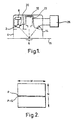
- a tile inspection apparatus is schematically illustrated in figure 1.
- the apparatus comprises a fluorescent light source 2 positioned inside an enclosure 4 which serves to exclude ambient light from entering an inspection region, generally indicated at 6.
- the fluorescent light source is connected to an adjustable power supply 8.
- a photo-detector 10 is positioned adjacent the light source 2 and provides a signal indicative of the intensity of the light source to the power supply 8 in order that the intensity of the light source can be controlled in a closed loop manner.
- the light source 2 is partitioned from first and second cameras 12 and 14 which are arranged to collect diffusely and specularly reflected light from the inspection region, respectively. Tiles are conveyed to and from the inspection region 6 by a conveyor 15 which runs continuously.
- the fluorescent light and power supply controller are held within a chamber which is forcibly air cooled. Whilst this helps to maintain the temperature of the photo detector 10 and the power supply broadly constant, it does not guarantee that these components will remain within a sufficiently tightly controlled temperature range such that drift is insignificant.
- a first end 20 of an optical fibre 22 is positioned adjacent a central portion of the fluorescent tube 2 and faces towards the tube in order to collect light therefrom.
- the optical fibre 22 delivers the light to one end of the detector array of the line scan camera 14.
- the second end of the fibre is positioned in the field of view on the line scan camera, facing towards the camera.
- fluctuations caused by drift in the output of the fluorescent light 2 or in the response of the line scan camera can be continuously monitored by a data processor 26.
- the data processor also receives an output from the area camera 12.
- line scan cameras offer optical solutions which are advantageous in the field of machine vision systems, namely that perspective effects are not introduced into the system.
- area cameras are used more commonly throughout industry, and as a consequence of mass production are less expensive than line scan cameras.
- an area camera has a two dimensional array of picture elements.
- the array typically has M elements in a first direction and N elements in a second direction.
- M and N are typically equal to 840 and 625, respectively.
- a line scan camera can be fabricated from an area camera by only selecting the data from one of the lines of the camera, for example a Pth line.
- true line scan cameras exhibit read rates greatly in excess of the frame rates possessed by area cameras.
- the conveyor belt speed would need to be drastically reduced in order to use an area camera as a line scan camera.
- an area camera to view a narrow band, defined between the Pth and P+Qth lines of an area camera its is possible to use an area camera to capture views similar to that which would be obtained from a line camera, and to use the multiple lines within the narrow band to capture multiple line views such that the speed of throughput through the machine vision system does not become compromised.
- the above description has, for brevity, ignored the fact that the area cameras may provide interlaced images. However, this does not provide a significant problem to the use of an area camera as a band scan camera. Where the camera is used to view items travelling on a conveyor, the width of the band is selected to be at least equal to the distance travelled by the conveyor during the time between scans in order to ensure that the entirety of the surface under inspection is viewed.
- the remaining bands may be used for other purposes.
- Such other uses may include capturing alternative views of the item under inspection, or monitoring the light emanating from the light source.
- the camera may be arranged to view the light source directly. In such an arrangement, the full length of the light source can be monitored as can the response of a full line of the camera.
Landscapes
- Engineering & Computer Science (AREA)
- Textile Engineering (AREA)
- Physics & Mathematics (AREA)
- Health & Medical Sciences (AREA)
- Life Sciences & Earth Sciences (AREA)
- Chemical & Material Sciences (AREA)
- Analytical Chemistry (AREA)
- Biochemistry (AREA)
- General Health & Medical Sciences (AREA)
- General Physics & Mathematics (AREA)
- Immunology (AREA)
- Pathology (AREA)
- Investigating Materials By The Use Of Optical Means Adapted For Particular Applications (AREA)
Claims (8)
- Système de vision mécanique destiné à l'inspection automatique d'objets, le système de vision mécanique comprenant au moins une source lumineuse (2) et au moins une caméra (12, 14), la source lumineuse éclairant une surface (6) à inspecter, l'au moins une caméra voyant la surface à inspecter, caractérisé en ce qu'il est prévu un chemin optique additionnel (22) de telle manière qu'au moins une des caméras reçoive de la lumière de l'au moins une source lumineuse afin de surveiller sa sortie et pendant qu'elle voit aussi la surface à inspecter.
- Système de vision mécanique selon la revendication 1, caractérisé par une caméra (12) agencée pour voir de la lumière dispersée avec diffusion en provenance de la surface (6).
- Système de vision mécanique selon la revendication 1 ou 2, caractérisé par une caméra (14) agencée pour voir de la lumière réfléchie spéculairement en provenance de la surface (6).
- Système de vision mécanique selon une quelconque des revendications précédentes, caractérisé en ce que les caméras sont des caméras à exploration linéaire, des caméras à surface ou des caméras à exploration par bandes.
- Système de vision mécanique selon une quelconque des revendications précédentes, caractérisé en ce que le chemin optique additionnel est formé par un guide de lumière (22).
- Système de vision mécanique selon la revendication 5, caractérisé en ce que le guide de lumière (22) est un câble à fibre optique dont une première extrémité est agencée pour collecter de la lumière en provenance d'une partie de la source lumineuse et dont une deuxième extrémité est agencée pour éclairer une partie d'un groupement de détecteurs d'une caméra.
- Système de vision mécanique selon une quelconque des revendications 1 à 4, caractérisé en ce que le chemin optique utilise des miroirs pour diriger la lumière vers l'au moins une caméra.
- Système de vision mécanique selon une quelconque des revendications précédentes, caractérisé en ce qu'une des caméras est une caméra à surface et est agencée pour voir simultanément l'objet étudié et la source lumineuse (2).
Applications Claiming Priority (2)
| Application Number | Priority Date | Filing Date | Title |
|---|---|---|---|
| GBGB9827377.4A GB9827377D0 (en) | 1998-12-11 | 1998-12-11 | Machine vision system and tile inspection apparatus incorporating such a system |
| GB9827377 | 1998-12-11 |
Publications (2)
| Publication Number | Publication Date |
|---|---|
| EP1008846A1 EP1008846A1 (fr) | 2000-06-14 |
| EP1008846B1 true EP1008846B1 (fr) | 2005-04-06 |
Family
ID=10844105
Family Applications (1)
| Application Number | Title | Priority Date | Filing Date |
|---|---|---|---|
| EP99309990A Revoked EP1008846B1 (fr) | 1998-12-11 | 1999-12-10 | Système de vision artificiel et appareil d'inspection des tuiles utilisant un tel système |
Country Status (4)
| Country | Link |
|---|---|
| EP (1) | EP1008846B1 (fr) |
| AT (1) | ATE292798T1 (fr) |
| DE (1) | DE69924588D1 (fr) |
| GB (1) | GB9827377D0 (fr) |
Families Citing this family (1)
| Publication number | Priority date | Publication date | Assignee | Title |
|---|---|---|---|---|
| CN205607880U (zh) * | 2016-02-02 | 2016-09-28 | 意力(广州)电子科技有限公司 | 一种基于自动光学检测程序的触摸面板自动检测设备 |
Family Cites Families (7)
| Publication number | Priority date | Publication date | Assignee | Title |
|---|---|---|---|---|
| US4373804A (en) * | 1979-04-30 | 1983-02-15 | Diffracto Ltd. | Method and apparatus for electro-optically determining the dimension, location and attitude of objects |
| JP2862477B2 (ja) * | 1993-06-29 | 1999-03-03 | キヤノン株式会社 | 露光装置及び該露光装置を用いてデバイスを製造する方法 |
| WO1995018952A1 (fr) * | 1994-01-07 | 1995-07-13 | Honeywell Ag | Procede de mesure de la rugosite de la surface d'un materiau |
| US5519204A (en) * | 1994-04-25 | 1996-05-21 | Cyberoptics Corporation | Method and apparatus for exposure control in light-based measurement instruments |
| GB9614073D0 (en) * | 1996-07-04 | 1996-09-04 | Surface Inspection Ltd | Visual inspection apparatus |
| US5753903A (en) * | 1996-11-05 | 1998-05-19 | Medar, Inc. | Method and system for controlling light intensity in a machine vision system |
| WO1998034096A1 (fr) * | 1997-01-31 | 1998-08-06 | Medar, Inc. | Procede et systeme pour detecter des defauts dans des objets transparents ayant des variations spatiales dans leur densite optique |
-
1998
- 1998-12-11 GB GBGB9827377.4A patent/GB9827377D0/en not_active Ceased
-
1999
- 1999-12-10 DE DE69924588T patent/DE69924588D1/de not_active Expired - Lifetime
- 1999-12-10 EP EP99309990A patent/EP1008846B1/fr not_active Revoked
- 1999-12-10 AT AT99309990T patent/ATE292798T1/de not_active IP Right Cessation
Also Published As
| Publication number | Publication date |
|---|---|
| ATE292798T1 (de) | 2005-04-15 |
| GB9827377D0 (en) | 1999-02-03 |
| DE69924588D1 (de) | 2005-05-12 |
| EP1008846A1 (fr) | 2000-06-14 |
Similar Documents
| Publication | Publication Date | Title |
|---|---|---|
| US6011620A (en) | Method and apparatus for the automatic inspection of optically transmissive planar objects | |
| US4972093A (en) | Inspection lighting system | |
| US5095204A (en) | Machine vision inspection system and method for transparent containers | |
| US4767924A (en) | Apparatus for optical monitoring with a high pressure lamp connected to a fiber optic cable | |
| CN108778532B (zh) | 用于检查物流式行进物品的检查机和检查方法 | |
| US8451440B2 (en) | Apparatus for the optical inspection of wafers | |
| GB2189623A (en) | Remote reading spectrophotometer | |
| AU606050B2 (en) | Fiber optic imaging system for on-line monitoring | |
| US7245386B2 (en) | Object measuring device and associated methods | |
| WO2011147385A2 (fr) | Procédé et dispositif de détection en continu de l'épaisseur et/ou de l'homogénéité d'objets linéaires, en particulier de fibres textiles, et mise en œuvre/utilisation du procédé/dispositif | |
| US5274243A (en) | Cylindrical allumination system for inspection of sheet material | |
| KR20190010589A (ko) | 벌크재 검사장치 및 방법 | |
| KR100814062B1 (ko) | 연속적으로 이동되는 투과 가능한 판재의 자동 결함 검사시스템 및 자동 결함 검사방법 | |
| US7557922B2 (en) | Detection system for use in a sorting apparatus, a method for determining drift in the detection system and a sorting apparatus comprising such detection system | |
| US6188784B1 (en) | Split optics arrangement for vision inspection/sorter module | |
| EP1008846B1 (fr) | Système de vision artificiel et appareil d'inspection des tuiles utilisant un tel système | |
| EP0843974A2 (fr) | Procédé et dispositif de contrÔle sans contact des extrémités des cigarettes ou analogues | |
| FI80959B (fi) | Foerfarande och anordning foer inspektion av spegelreflexionsytor. | |
| KR20010080190A (ko) | 웨이퍼 가공 장치에서 웨이퍼 파편 검출 시스템 및 방법 | |
| US4824209A (en) | Light source assembly | |
| JPH11248643A (ja) | 透明フィルムの異物検査装置 | |
| WO2017103927A1 (fr) | Procédé et appareil pour inspection de substrats | |
| EP1034048B1 (fr) | Arrangement et procede pour trier des granules | |
| EP1074831A1 (fr) | Procede et dispositif de mirage d'oeufs | |
| KR20040039294A (ko) | 작은 입자를 조사하여 입자의 품질을 분석하기 위한 방법및 장치 |
Legal Events
| Date | Code | Title | Description |
|---|---|---|---|
| PUAI | Public reference made under article 153(3) epc to a published international application that has entered the european phase |
Free format text: ORIGINAL CODE: 0009012 |
|
| AK | Designated contracting states |
Kind code of ref document: A1 Designated state(s): AT BE CH CY DE DK ES FI FR GB GR IE IT LI LU MC NL PT SE |
|
| AX | Request for extension of the european patent |
Free format text: AL;LT;LV;MK;RO;SI |
|
| 17P | Request for examination filed |
Effective date: 20001211 |
|
| AKX | Designation fees paid |
Free format text: AT BE CH CY DE DK ES FI FR GB GR IE IT LI LU MC NL PT SE |
|
| 17Q | First examination report despatched |
Effective date: 20030310 |
|
| GRAP | Despatch of communication of intention to grant a patent |
Free format text: ORIGINAL CODE: EPIDOSNIGR1 |
|
| GRAS | Grant fee paid |
Free format text: ORIGINAL CODE: EPIDOSNIGR3 |
|
| GRAA | (expected) grant |
Free format text: ORIGINAL CODE: 0009210 |
|
| AK | Designated contracting states |
Kind code of ref document: B1 Designated state(s): AT BE CH CY DE DK ES FI FR GB GR IE IT LI LU MC NL PT SE |
|
| PG25 | Lapsed in a contracting state [announced via postgrant information from national office to epo] |
Ref country code: NL Free format text: LAPSE BECAUSE OF FAILURE TO SUBMIT A TRANSLATION OF THE DESCRIPTION OR TO PAY THE FEE WITHIN THE PRESCRIBED TIME-LIMIT Effective date: 20050406 Ref country code: LI Free format text: LAPSE BECAUSE OF FAILURE TO SUBMIT A TRANSLATION OF THE DESCRIPTION OR TO PAY THE FEE WITHIN THE PRESCRIBED TIME-LIMIT Effective date: 20050406 Ref country code: IT Free format text: LAPSE BECAUSE OF FAILURE TO SUBMIT A TRANSLATION OF THE DESCRIPTION OR TO PAY THE FEE WITHIN THE PRESCRIBED TIME-LIMIT;WARNING: LAPSES OF ITALIAN PATENTS WITH EFFECTIVE DATE BEFORE 2007 MAY HAVE OCCURRED AT ANY TIME BEFORE 2007. THE CORRECT EFFECTIVE DATE MAY BE DIFFERENT FROM THE ONE RECORDED. Effective date: 20050406 Ref country code: FI Free format text: LAPSE BECAUSE OF FAILURE TO SUBMIT A TRANSLATION OF THE DESCRIPTION OR TO PAY THE FEE WITHIN THE PRESCRIBED TIME-LIMIT Effective date: 20050406 Ref country code: ES Free format text: LAPSE BECAUSE OF FAILURE TO SUBMIT A TRANSLATION OF THE DESCRIPTION OR TO PAY THE FEE WITHIN THE PRESCRIBED TIME-LIMIT Effective date: 20050406 Ref country code: CH Free format text: LAPSE BECAUSE OF FAILURE TO SUBMIT A TRANSLATION OF THE DESCRIPTION OR TO PAY THE FEE WITHIN THE PRESCRIBED TIME-LIMIT Effective date: 20050406 Ref country code: BE Free format text: LAPSE BECAUSE OF FAILURE TO SUBMIT A TRANSLATION OF THE DESCRIPTION OR TO PAY THE FEE WITHIN THE PRESCRIBED TIME-LIMIT Effective date: 20050406 Ref country code: AT Free format text: LAPSE BECAUSE OF FAILURE TO SUBMIT A TRANSLATION OF THE DESCRIPTION OR TO PAY THE FEE WITHIN THE PRESCRIBED TIME-LIMIT Effective date: 20050406 |
|
| REG | Reference to a national code |
Ref country code: GB Ref legal event code: FG4D |
|
| REG | Reference to a national code |
Ref country code: CH Ref legal event code: EP |
|
| REG | Reference to a national code |
Ref country code: IE Ref legal event code: FG4D |
|
| REF | Corresponds to: |
Ref document number: 69924588 Country of ref document: DE Date of ref document: 20050512 Kind code of ref document: P |
|
| PG25 | Lapsed in a contracting state [announced via postgrant information from national office to epo] |
Ref country code: SE Free format text: LAPSE BECAUSE OF FAILURE TO SUBMIT A TRANSLATION OF THE DESCRIPTION OR TO PAY THE FEE WITHIN THE PRESCRIBED TIME-LIMIT Effective date: 20050706 Ref country code: GR Free format text: LAPSE BECAUSE OF FAILURE TO SUBMIT A TRANSLATION OF THE DESCRIPTION OR TO PAY THE FEE WITHIN THE PRESCRIBED TIME-LIMIT Effective date: 20050706 Ref country code: DK Free format text: LAPSE BECAUSE OF FAILURE TO SUBMIT A TRANSLATION OF THE DESCRIPTION OR TO PAY THE FEE WITHIN THE PRESCRIBED TIME-LIMIT Effective date: 20050706 |
|
| PG25 | Lapsed in a contracting state [announced via postgrant information from national office to epo] |
Ref country code: DE Free format text: LAPSE BECAUSE OF FAILURE TO SUBMIT A TRANSLATION OF THE DESCRIPTION OR TO PAY THE FEE WITHIN THE PRESCRIBED TIME-LIMIT Effective date: 20050707 |
|
| PG25 | Lapsed in a contracting state [announced via postgrant information from national office to epo] |
Ref country code: PT Free format text: LAPSE BECAUSE OF FAILURE TO SUBMIT A TRANSLATION OF THE DESCRIPTION OR TO PAY THE FEE WITHIN THE PRESCRIBED TIME-LIMIT Effective date: 20050908 |
|
| NLV1 | Nl: lapsed or annulled due to failure to fulfill the requirements of art. 29p and 29m of the patents act | ||
| REG | Reference to a national code |
Ref country code: CH Ref legal event code: PL |
|
| PG25 | Lapsed in a contracting state [announced via postgrant information from national office to epo] |
Ref country code: CY Free format text: LAPSE BECAUSE OF FAILURE TO SUBMIT A TRANSLATION OF THE DESCRIPTION OR TO PAY THE FEE WITHIN THE PRESCRIBED TIME-LIMIT Effective date: 20051210 |
|
| PG25 | Lapsed in a contracting state [announced via postgrant information from national office to epo] |
Ref country code: IE Free format text: LAPSE BECAUSE OF NON-PAYMENT OF DUE FEES Effective date: 20051212 |
|
| PG25 | Lapsed in a contracting state [announced via postgrant information from national office to epo] |
Ref country code: MC Free format text: LAPSE BECAUSE OF NON-PAYMENT OF DUE FEES Effective date: 20051231 Ref country code: LU Free format text: LAPSE BECAUSE OF NON-PAYMENT OF DUE FEES Effective date: 20051231 |
|
| PLBI | Opposition filed |
Free format text: ORIGINAL CODE: 0009260 |
|
| PLAX | Notice of opposition and request to file observation + time limit sent |
Free format text: ORIGINAL CODE: EPIDOSNOBS2 |
|
| 26 | Opposition filed |
Opponent name: MASSEN MACHINE VISION SYSTEMS GMBH Effective date: 20051222 |
|
| EN | Fr: translation not filed | ||
| PLBB | Reply of patent proprietor to notice(s) of opposition received |
Free format text: ORIGINAL CODE: EPIDOSNOBS3 |
|
| REG | Reference to a national code |
Ref country code: IE Ref legal event code: MM4A |
|
| PGFP | Annual fee paid to national office [announced via postgrant information from national office to epo] |
Ref country code: GB Payment date: 20061219 Year of fee payment: 8 |
|
| RDAF | Communication despatched that patent is revoked |
Free format text: ORIGINAL CODE: EPIDOSNREV1 |
|
| RDAG | Patent revoked |
Free format text: ORIGINAL CODE: 0009271 |
|
| STAA | Information on the status of an ep patent application or granted ep patent |
Free format text: STATUS: PATENT REVOKED |
|
| 27W | Patent revoked |
Effective date: 20071202 |
|
| GBPR | Gb: patent revoked under art. 102 of the ep convention designating the uk as contracting state |
Effective date: 20071202 Free format text: 20071202 |
|
| PG25 | Lapsed in a contracting state [announced via postgrant information from national office to epo] |
Ref country code: FR Free format text: LAPSE BECAUSE OF NON-PAYMENT OF DUE FEES Effective date: 20061231 |
|
| PG25 | Lapsed in a contracting state [announced via postgrant information from national office to epo] |
Ref country code: FR Free format text: LAPSE BECAUSE OF NON-PAYMENT OF DUE FEES Effective date: 20051231 |
|
| PG25 | Lapsed in a contracting state [announced via postgrant information from national office to epo] |
Ref country code: FR Free format text: LAPSE BECAUSE OF NON-PAYMENT OF DUE FEES Effective date: 20050406 |
|
| PLAB | Opposition data, opponent's data or that of the opponent's representative modified |
Free format text: ORIGINAL CODE: 0009299OPPO |