EP1008808B1 - Verfahren zur Regelung der Verbrennungsluft und entsprechende Regelungsanordnung - Google Patents
Verfahren zur Regelung der Verbrennungsluft und entsprechende Regelungsanordnung Download PDFInfo
- Publication number
- EP1008808B1 EP1008808B1 EP99660185A EP99660185A EP1008808B1 EP 1008808 B1 EP1008808 B1 EP 1008808B1 EP 99660185 A EP99660185 A EP 99660185A EP 99660185 A EP99660185 A EP 99660185A EP 1008808 B1 EP1008808 B1 EP 1008808B1
- Authority
- EP
- European Patent Office
- Prior art keywords
- grate
- primary air
- firebox
- wood
- air
- Prior art date
- Legal status (The legal status is an assumption and is not a legal conclusion. Google has not performed a legal analysis and makes no representation as to the accuracy of the status listed.)
- Expired - Lifetime
Links
Images


Classifications
-
- F—MECHANICAL ENGINEERING; LIGHTING; HEATING; WEAPONS; BLASTING
- F23—COMBUSTION APPARATUS; COMBUSTION PROCESSES
- F23L—SUPPLYING AIR OR NON-COMBUSTIBLE LIQUIDS OR GASES TO COMBUSTION APPARATUS IN GENERAL ; VALVES OR DAMPERS SPECIALLY ADAPTED FOR CONTROLLING AIR SUPPLY OR DRAUGHT IN COMBUSTION APPARATUS; INDUCING DRAUGHT IN COMBUSTION APPARATUS; TOPS FOR CHIMNEYS OR VENTILATING SHAFTS; TERMINALS FOR FLUES
- F23L9/00—Passages or apertures for delivering secondary air for completing combustion of fuel
-
- F—MECHANICAL ENGINEERING; LIGHTING; HEATING; WEAPONS; BLASTING
- F23—COMBUSTION APPARATUS; COMBUSTION PROCESSES
- F23L—SUPPLYING AIR OR NON-COMBUSTIBLE LIQUIDS OR GASES TO COMBUSTION APPARATUS IN GENERAL ; VALVES OR DAMPERS SPECIALLY ADAPTED FOR CONTROLLING AIR SUPPLY OR DRAUGHT IN COMBUSTION APPARATUS; INDUCING DRAUGHT IN COMBUSTION APPARATUS; TOPS FOR CHIMNEYS OR VENTILATING SHAFTS; TERMINALS FOR FLUES
- F23L1/00—Passages or apertures for delivering primary air for combustion
- F23L1/02—Passages or apertures for delivering primary air for combustion by discharging the air below the fire
Definitions
- the present invention relates to a method as defined in the preamble of claim 1 and to a regulation arrangement as defined in the preamble of claim 9 for regulating combustion air in conjunction with the combustion of wood in a heat-storing fireplace.
- a fire grate For burning wood in heat-storing fireplaces, generally a fire grate is used and the wood charge to be burned is placed on the grate.
- the wood For fast and efficient ignition, the wood needs plenty of combustion air, which is mainly supplied through the grate as primary air flowing into the wood charge. In this way, the wood charge is effectively ignited and its gasification is started quickly.
- many fireplaces use secondary air, which is supplied to the space above the wood charge, which generally is not the hottest point in the combustion process, where the combustible gases released from the wood are burned with the aid of secondary air. Without secondary air, a considerable portion of the gases would flow out through the smoke flue, unburned due to an insufficient supply of oxygen.
- NL-A-8303987 discloses an arrangement for the regulation of combustion air when wood is burned.
- the arrangement comprises a firebox delimited horizontally by side walls and a back wall and a door, a grate forming the bottom of the firebox and an ash box below the grate.
- the primary combustion air is directed through the grate into the firebox.
- the grate comprises regulating elements to allow regulation of air passing through the grate.
- the secondary combustion air is directed through flow channels provided at the edges of the grate from below the grate to the vicinity of the firebox walls.
- US-A-4469085 discloses an arrangement of two grates fitted one above the other and in contact with one another.
- One of the grates is movable with respect to the other, the width of each passage opening in one of the grates is greater in the middle of the grate, permitting to close gradually from their ends the passage openings of the other grate during the displacement of one of said grates.
- the object of the invention is to eliminate the drawbacks referred to above.
- a specific object of the invention is to disclose a new type of method and a corresponding regulation arrangement which will allow wood to be burned in a heat-storing fireplace as effectively as possible and so that over-gasification of the fuel wood is prevented.
- the combustion air is divided into a primary air and a secondary air, the primary air is supplied through the grate under the wood charge and the secondary air is supplied into the firebox above the wood.
- the primary air is devided into an auxiliary primary air and a main primary air, only the amount of the auxiliary primary air is adjusted through the middle area of the grate under the wood charge and the main primary air through the edge areas of the grate is kept continuous.
- the primary air is caused to flow under the wood charge in the edge areas of the grate.
- the gases released from the wood charge will be completely burned in the abundant secondary air flow which, being preheated, is immediately available around the wood charge for combustion.
- the primary air flow through the grate mainly in its edge areas is kept continuous even during ignition, but the auxiliary primary air flows in the middle part of the grate are appropriately throttled after the charge has been ignited or in conjunction with the first addition of a wood charge.
- the openings for auxiliary primary air flow are closed completely after the wood has been ignited or in conjunction with the first addition of wood into the firebox, the primary air for the gasification of the wood being supplied under the wood charge as a main primary air flow directed to the edge areas of the charge.
- the secondary air is preferably supplied into the firebox around the wood charge as an air flow as smooth as possible and surrounding the wood charge on all sides except the under side.
- secondary air may be flowing on both sides of the wood charge, behind the wood charge, in front of and/or above the wood charge.
- the heat-storing fireplace used in the arrangement of the invention for the regulation of combustion air comprises a firebox horizontally delimited by side walls and a back wall and a door, a grate forming the bottom of the firebox and a space under the grate, often an ash box, through which combustion air can be passed into the firebox.
- a firebox horizontally delimited by side walls and a back wall and a door
- a grate forming the bottom of the firebox and a space under the grate, often an ash box, through which combustion air can be passed into the firebox.
- Other ways of supplying combustion air from below the grate into the firebox may also be used.
- Disposed at the edges of the grate are also ducts for passing secondary air from below the grate around the firebox on all four sides of the wood charge so that the secondary air will surround the entire fuel wood charge.
- the edge areas of the grate are provided with always open main primary air holes and the middle area of the grate is provided with auxiliary primary air holes only in conjunction of which regulating elements are provided to allow regulation of air flow passing through them.
- the total maximum cross-sectional area of the auxiliary primary air holes is many times larger than the total cross-sectional area of the main primary air holes. Therefore, when the fuel wood is being ignited, a large primary air flow can be supplied from under the wood, but on the other hand, at a later stage during the combustion of the wood, the primary air flow can be adjusted to a suitable level with respect to the secondary air flow and the combustion.
- the side walls and/or back wall of the firebox are preferably provided with vertical grooves with their open sides facing toward the firebox, said grooves directing the secondary air flowing along the air ducts at the edges of the grate into the firebox, around and above the fuel wood.
- the secondary air is effectively heated in the grooves and at the same time the secondary air flow prevents overheating of the walls of the firebox.
- the grooves form a rising channel through which secondary combustion air can effectively flow around and above the wood in the firebox regardless of how far the firebox is filled with wood.
- the grooves may be made directly in the stone walls of the firebox or they may be implemented using separate elements placed at the edges of the firebox.
- the function of the grooves is to allow the combustion gases to flow past the wood charge in a fully loaded firebox, whereas in the present invention the grooves expressly function as a channel for passing combustion air from below the wood charge to its sides and above it.
- the flow channels may be disposed inside the firebox side walls or on their surface, and the channels may consist of a stone or metal structure or a suitable cast structure or suitable masonry.
- the channels may serve to supply secondary air above the wood charge and also to its sides. Therefore, the implementation of the vertical secondary air flows is not defined in more definite terms, but the essential point is that sufficiently ample amounts of secondary air can be supplied from below the grate and passed around and above the burning wood charge.
- the method of the invention and the corresponding regulation arrangement have significant advantages as compared with prior art.
- the invention allows considerably more efficient combustion of wood than is possible in currently used heat-storing fireplaces.
- the invention effectively prevents excessive and sudden gasification of wood already ignited or wood added into a hot furnace, and thus it allows the combustion of all combustible gases in the firebox, thereby preventing unburned gases from getting into the chimney flue.
- the temperature variations of the combustion gases remain at a minimum.
- the temperatures remain at a steady high level all the time during heating, so the storage performance of the fireplace is also at a maximum.
- the invention significantly improves the final result of combustion, which also means substantially cleaner combustion gases.
- uniform combustion in the fireplace is achieved and excessive temperatures are prevented, thereby increasing the durability of the structures and prolonging their service life.
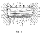
- the heat-storing fireplace as presented in Fig. 1 and 2 comprises a firebox 11, which again comprises side walls 12 and a back wall 13 and a door in the front, which is not shown in the drawings.
- the bottom of the firebox is formed by a grate 2 and an ash box 3 below the grate.
- all combustion air 1 is supplied into the firebox 11 exclusively through the ash box 3.
- the grate 2 In its middle area, the grate 2 is provided with a number of auxiliary primary air holes 14, and on the lower surface of the grate in the region of the holes there are regulating elements 17, i.e. a suitable slidable damper or shutter, by means of which the auxiliary primary air holes can be closed and opened as desired.
- regulating elements 17 i.e. a suitable slidable damper or shutter, by means of which the auxiliary primary air holes can be closed and opened as desired.
- auxiliary primary air holes 14 i.e. in the edge areas of the grate 2
- main primary air holes 15 which are always open and are therefore not provided with any regulating elements.
- the edge of the grate consists of a flange 19 pointing in an oblique upward direction, the grate being only supported by ribs 21 on the edges 20 of the ash box.
- flow channels 16 are formed below the flanges 19 of the grate, through which channels the secondary air portion of the combustion air 1 can flow near both the side walls and back wall of the firebox and via the front edge into the front part of the firebox. In this way, the wood charge is surrounded by a rising flow of secondary air 6.
- the walls of the firebox are provided with upright grooves 18 laid vertically, with their open sides facing toward the firebox, the flow of secondary combustion air being guided into these grooves by the flow channels 16.
- the grooves 18 pass the secondary combustion air further up around and above the wood charge burning in the firebox.
- Fig. 1 and 2 The regulation arrangement of the invention presented in Fig. 1 and 2 works as follows.
- a wood charge is to be kindled, the wood charge 4 is placed on the grate 2 and ignited, keeping the auxiliary primary air holes 14 fully open.
- a maximum amount of primary air is supplied to the wood charge, so it will start burning rapidly.
- the gasification of the wood is started quickly, combustion is accelerated fast and the entire fireplace and chimney flue are warmed up, so a natural draught is set up in the flue.
- the auxiliary primary air holes, main primary air holes and the secondary air flow channels are all fully open and the combustion air 1 is divided roughly equally between the primary air and secondary air flows.
- the auxiliary secondary air flow is about 4-6 times as large as the main primary air flow.
- the auxiliary primary air holes 14 are preferably closed completely, but they can also be left slightly open.
- the combustion air 1 is only divided between the main primary air holes 15 and the secondary air flow. In this case, only 15-20 % of the total combustion air 1 is passed through the main primary air holes 15 under the hot embers 8 and the wood charge 7. The remaining portion of the combustion air is supplied as a secondary air flow 10 to the front, lateral, back and top sides of the wood charge.
- the gasification of the wood charge can be regulated and limited, in other words, the rate of gasification of the wood charge is limited to a level such that a significant amount of secondary combustion air can be supplied around and above the wood charge so as to cause all the combustible gases to burn already in the firebox, thus preventing unburned gases from getting into the chimney flue.
- the combustion efficiency is also increased by the fact that a large secondary air flow is flowing in the firebox near its walls, this air flow being thus heated by the intensive radiated heat from the embers 8 and the combustion process before the secondary combustion.
- the secondary combustion air flow keeps the temperature of the firebox walls relatively low, thus prolonging their service life and increasing their durability in spite of the high temperature, which may reach a level as high as 1200°C.
- Figures 3 and 4 present a firebox structure corresponding to figures 1 and 2 as seen from above.
- the grate 2 forms the bottom of the firebox.
- auxiliary primary air holes 14 In the middle area of the grate there are number of auxiliary primary air holes 14, and around these, i.e. on both sides of this group of holes, there are three main primary air holes 15 arranged in a line.
- transverse slit 23 At the front edge of the grate, behind the door 22, there is a transverse slit 23 leading from below the edge flange 19 of the grate into the ash box.
- both side walls 12 and the back wall 13 are provided with a number of vertical grooves 18 open toward the firebox. The grooves extend from below the grate 2, i.e.
- the firebox can be completely filled with wood right to the walls 12 and 13. In spite of this, an effective secondary air flow via the channels 18 is formed around the wood charge.
- Fig. 3 also presents a possible additional embodiment in which the side walls 12 and the back wall 13 of the firebox are provided with flow channels 27 placed between the grooves 18 and supplying secondary air from below the grate to the upper part of the firebox, either only above the wood charge or also partly to the level of the wood charge.
- the secondary air rising in the flow channels effectively cools the stone structure between the grooves, preventing overheating of the stones.
- These channels can also be used to supply unburned air with a high oxygen content to a desired point in the upper part of the firebox.
- Fig. 5 presents another embodiment of the invention, in which, as in Fig. 3, the grate 2 is provided with auxiliary primary air holes 14 and main primary air holes 15 as well as a slit 23 at the front edge of the grate behind the door 22.
- the side walls 12 and the back wall 13 of the firebox have smooth surfaces, and the firebox is provided with vertical bars or ribs 24 placed in direct contact with the walls.
- the vertical bars or ribs are connected to each other in a suitable manner, e.g. by their upper and lower edges via intermediate brackets 25.
- the grate 2 does not extend right up to the walls 12 and 13, there are passages 26 formed between the grate edge, the walls 12 and 13 and the ribs 24, allowing secondary air to rise from below the grate and get around and above the wood charge on the grate.
- the bars or ribs may form a frame which is only placed loose on the grate against the walls of the firebox. This structure and the intensive air flow rising in it give an effective protection against overheating of the firebox.
Landscapes
- Engineering & Computer Science (AREA)
- Chemical & Material Sciences (AREA)
- Combustion & Propulsion (AREA)
- Mechanical Engineering (AREA)
- General Engineering & Computer Science (AREA)
- Solid-Fuel Combustion (AREA)
- Regulation And Control Of Combustion (AREA)
Claims (13)
- Verfahren zum Regeln von Verbrennungsluft, wenn Holz in einem wärmespeichernden Kamin verbrannt wird, in den die gesamte Verbrennungsluft (1) von unterhalb eines Rostes (2) in den Feuerraum geliefert wird,dadurch gekennzeichnet, dassdie Verbrennungsluft (1) wird in eine Primärluft und eine Sekundärluft (10) geteilt,die Primärluft wird durch den Rost unter die Holzbeschickung geliefert unddie Sekundärluft wird in den Feuerraum oberhalb des Holzes geliefert,die Primärluft wird in eine Hilfsprimärluft (5) und eine Hauptprimärluft (9) geteilt,nur die Menge der Hilfsprimärluft (5) wird eingestellt durch den mittleren Bereich des Rostes (2) unter der Holzbeschickung unddie Hauptprimärluft (9) durch die Kantenbereiche des Rostes (2) wird kontinuierlich gehalten.
- Verfahren nach Anspruch 1, dadurch gekennzeichnet, dass die Hauptprimärluftströmung (9) so unter die Holzbeschickung (4) geliefert wird, dass sie von der Mitte zu den Kanten zunimmt.
- Verfahren nach Anspruch 1, dadurch gekennzeichnet, dass die Hauptprimärluft (9) nur in den Kantenbereichen der Holzbeschickung unter die Holzbeschickung (4) geliefert wird.
- Verfahren nach Anspruch 1, dadurch gekennzeichnet, dass die Hauptprimärluft (9) nur in den Kantenbereichen des Rostes (2) unter die Holzbeschickung geliefert wird.
- Verfahren nach einem der Ansprüche 1 bis 4, dadurch gekennzeichnet, dass die Öffnungen in dem mittleren Bereich des Rostes (2) für die Strömung der Hilfsprimärluft (5) gedrosselt sind.
- Verfahren nach einem der Ansprüche 1 bis 4, dadurch gekennzeichnet, dass die Öffnungen für die Strömung der Hilfsprimärluft in dem mittleren Bereich des Rostes (2) geschlossen sind.
- Verfahren nach einem der Ansprüche 1 bis 6, dadurch gekennzeichnet, dass die Hauptprimärluft (9) durch den Rost über getrennte individuelle Entladungslöcher hindurchgeht, so dass die Hauptprimärluftströmung intensive, scharfe Primärluftstrahlen in die Kantenbereiche der Holzbeschickung bildet.
- Verfahren nach einem der Ansprüche 1 bis 7, dadurch gekennzeichnet, dass die Sekundärluft so in den Feuerraum geliefert wird, dass sie eine Luftumhüllung bildet, die im Wesentlichen die Holzbeschickung umgibt.
- Anordnung zum Regeln der Verbrennungsluft, wenn Holz in einem wärmespeichernden Kamin verbrannt wird, welche aufweist:dadurch gekennzeichnet, dasseinen Feuerraum (11), der horizontal durch Seitenwände (12) und eine Rückwand (13) und eine Tür begrenzt ist,einen Rost (2), der den Boden des Feuerraums bildet, undeinen Ascheraum (3) unterhalb des Rostes,Strömungskanäle (16) an den Kanten des Rostes zum Hindurchführen von Sekundärluft von unterhalb des Rostes in die Nähe der Feuerraumwände,die Kantenbereiche des Rostes mit immer geöffneten Hauptprimärluftlöchern (15) versehen sind undder mittlere Bereich des Rostes (2) mit Hilfsprimärluftlöchern (14) versehen ist, wobei nur in Verbindung mit diesen Regelungselemente (17) vorgesehen sind, um eine Regulierung der durch sie hindurchgehenden Luftströmung zu ermöglichen.
- Regelungsvorrichtung nach Anspruch 9, dadurch gekennzeichnet, dass die Hauptprimärluftlöcher (15) um die Hilfsprimärluftlöcher (14) herum angeordnet sind.
- Regelungsvorrichtung nach Anspruch 9, dadurch gekennzeichnet, dass die gesamte maximale Querschnittsfläche der Hilfsprimärluftlöcher (14) mehrere Male so groß wie die gesamte Querschnittsfläche der Hauptprimärluftlöcher (15) ist.
- Regelungsvorrichtung nach einem der Ansprüche 9 bis 11, dadurch gekennzeichnet, dass die Seitenwände und/oder die Rückwand des Feuerraums mit Nuten (18) versehen sind, deren offene Seiten dem Feuerraum zugewandt sind, wobei die Nuten die Sekundärluftströmung über Strömungskanäle an den Kanten des Rostes zu dem oberen Teil des Feuerraums um das brennende Holz herum und über dieses leiten.
- Regelungsvorrichtung nach einem der Ansprüche 9 bis 11, dadurch gekennzeichnet, dass der Feuerraum Strömungskanäle aufweist, die nur an ihren Enden geöffnet sind und sich in den Seitenwänden und/oder der Rückwand des Feuerraums oder in deren Nähe befinden, wobei die Kanäle die durch die Strömungskanäle strömende Sekundärluft an den Kanten des Rostes zu dem oberen Teil des Feuerraums um das brennende und vergaste Holze herum und über dieses leiten.
Applications Claiming Priority (2)
| Application Number | Priority Date | Filing Date | Title |
|---|---|---|---|
| FI982692A FI115734B (fi) | 1998-12-11 | 1998-12-11 | Menetelmä paloilman ohjaamiseksi ja vastaava ohjausjäjestely |
| FI982692 | 1998-12-11 |
Publications (3)
| Publication Number | Publication Date |
|---|---|
| EP1008808A2 EP1008808A2 (de) | 2000-06-14 |
| EP1008808A3 EP1008808A3 (de) | 2000-12-20 |
| EP1008808B1 true EP1008808B1 (de) | 2005-01-26 |
Family
ID=8553098
Family Applications (1)
| Application Number | Title | Priority Date | Filing Date |
|---|---|---|---|
| EP99660185A Expired - Lifetime EP1008808B1 (de) | 1998-12-11 | 1999-12-03 | Verfahren zur Regelung der Verbrennungsluft und entsprechende Regelungsanordnung |
Country Status (4)
| Country | Link |
|---|---|
| EP (1) | EP1008808B1 (de) |
| AT (1) | ATE288052T1 (de) |
| DE (1) | DE69923418T2 (de) |
| FI (1) | FI115734B (de) |
Cited By (1)
| Publication number | Priority date | Publication date | Assignee | Title |
|---|---|---|---|---|
| WO2011059345A1 (en) * | 2009-11-13 | 2011-05-19 | Harts Gauld Trustees Limited | Manifold assembly |
Families Citing this family (3)
| Publication number | Priority date | Publication date | Assignee | Title |
|---|---|---|---|---|
| FI116985B (fi) * | 2002-01-25 | 2006-04-28 | Tulikivi Oyj | Tulisija ja menetelmä kiinteän polttoaineen polttamiseksi tulisijassa |
| DE102017110845A1 (de) * | 2017-05-18 | 2018-11-22 | Max Blank Gmbh | Brenngranulat-Heizgerät |
| FI20225059A1 (fi) * | 2022-01-25 | 2023-07-26 | Nunnauuni Oy | Leivinuuni |
Family Cites Families (6)
| Publication number | Priority date | Publication date | Assignee | Title |
|---|---|---|---|---|
| FR1100380A (fr) * | 1954-03-01 | 1955-09-20 | Ateliers Et Chantiers De Franc | Dispositif pour améliorer la combustion dans les foyers |
| BE893199A (nl) * | 1982-05-17 | 1982-09-16 | Vfm Verkoop Fab Metaalprod | Rooster voor de verbranding van vaste brandstoffen in kachels ovens en andere |
| CH661581A5 (en) * | 1983-10-10 | 1987-07-31 | Walter Spiess Ofen & Kochherdf | Device in a furnace space for the supply of secondary air |
| NL8303987A (nl) * | 1983-11-18 | 1985-06-17 | Haaras B V | Kachel voor vaste brandstof. |
| AT399572B (de) * | 1988-02-09 | 1995-06-26 | Karl Stefan Riener | Zuluftregelvorrichtung für eine heizeinrichtung |
| US5263471A (en) * | 1992-01-06 | 1993-11-23 | Shimek Ronald J | Solid fuel clean burning zero clearance fireplace |
-
1998
- 1998-12-11 FI FI982692A patent/FI115734B/fi not_active IP Right Cessation
-
1999
- 1999-12-03 AT AT99660185T patent/ATE288052T1/de active
- 1999-12-03 EP EP99660185A patent/EP1008808B1/de not_active Expired - Lifetime
- 1999-12-03 DE DE69923418T patent/DE69923418T2/de not_active Expired - Lifetime
Cited By (1)
| Publication number | Priority date | Publication date | Assignee | Title |
|---|---|---|---|---|
| WO2011059345A1 (en) * | 2009-11-13 | 2011-05-19 | Harts Gauld Trustees Limited | Manifold assembly |
Also Published As
| Publication number | Publication date |
|---|---|
| ATE288052T1 (de) | 2005-02-15 |
| FI982692A0 (fi) | 1998-12-11 |
| EP1008808A3 (de) | 2000-12-20 |
| DE69923418T2 (de) | 2006-03-23 |
| FI982692A (fi) | 2000-06-12 |
| EP1008808A2 (de) | 2000-06-14 |
| DE69923418D1 (de) | 2005-03-03 |
| FI115734B (fi) | 2005-06-30 |
Similar Documents
| Publication | Publication Date | Title |
|---|---|---|
| US4545360A (en) | Clean burning solid fuel stove and method | |
| US4141336A (en) | Fireplace stove | |
| US4201186A (en) | Solid-fuel burner | |
| US4201185A (en) | Method and means for heating by wood burning | |
| US4194487A (en) | Downdraft woodburning stove | |
| US4192285A (en) | Air tight fuel burning stove | |
| CA1162791A (en) | Furnaces | |
| US20080035137A1 (en) | Combustion apparatus | |
| KR20100137897A (ko) | 연기 발생이 없는 화목 연소장치 | |
| WO2000050817A1 (en) | Fireplace insert | |
| CA1136940A (en) | Solid fuel heater with improved primary/secondary air control system | |
| US4338913A (en) | Solid fuel burning stove | |
| EP1008808B1 (de) | Verfahren zur Regelung der Verbrennungsluft und entsprechende Regelungsanordnung | |
| US4207860A (en) | Wood-coal heating unit | |
| CA1158936A (en) | Fireplace furnace | |
| US4326495A (en) | Stove for solid fuel | |
| DK155463B (da) | Fastbraendselskedel, isaer til trae | |
| US3237622A (en) | Heater | |
| US4445496A (en) | Wood burning heater providing improved uniform temperature output | |
| US4279237A (en) | Combination stove and fireplace | |
| CA1166911A (en) | Furnace | |
| US4326496A (en) | Fireplace grate | |
| JP2678264B2 (ja) | 廃棄物燃料燃焼プラント | |
| US4444153A (en) | Grateless furnace for solid fuel | |
| EP4073434A1 (de) | Kamin, anordnung für einen kamin und verfahren für die sekundärluftzufuhr eines kamins |
Legal Events
| Date | Code | Title | Description |
|---|---|---|---|
| PUAI | Public reference made under article 153(3) epc to a published international application that has entered the european phase |
Free format text: ORIGINAL CODE: 0009012 |
|
| AK | Designated contracting states |
Kind code of ref document: A2 Designated state(s): AT BE CH CY DE DK ES FI FR GB GR IE IT LI LU MC NL PT SE |
|
| AX | Request for extension of the european patent |
Free format text: AL;LT;LV;MK;RO;SI |
|
| PUAL | Search report despatched |
Free format text: ORIGINAL CODE: 0009013 |
|
| AK | Designated contracting states |
Kind code of ref document: A3 Designated state(s): AT BE CH CY DE DK ES FI FR GB GR IE IT LI LU MC NL PT SE |
|
| AX | Request for extension of the european patent |
Free format text: AL;LT;LV;MK;RO;SI |
|
| 17P | Request for examination filed |
Effective date: 20010425 |
|
| AKX | Designation fees paid |
Free format text: AT BE CH CY DE DK ES FI FR GB GR IE IT LI LU MC NL PT SE |
|
| 17Q | First examination report despatched |
Effective date: 20030818 |
|
| GRAP | Despatch of communication of intention to grant a patent |
Free format text: ORIGINAL CODE: EPIDOSNIGR1 |
|
| GRAS | Grant fee paid |
Free format text: ORIGINAL CODE: EPIDOSNIGR3 |
|
| GRAA | (expected) grant |
Free format text: ORIGINAL CODE: 0009210 |
|
| AK | Designated contracting states |
Kind code of ref document: B1 Designated state(s): AT BE CH CY DE DK ES FI FR GB GR IE IT LI LU MC NL PT SE |
|
| REG | Reference to a national code |
Ref country code: GB Ref legal event code: FG4D |
|
| REG | Reference to a national code |
Ref country code: CH Ref legal event code: EP |
|
| REG | Reference to a national code |
Ref country code: IE Ref legal event code: FG4D |
|
| REF | Corresponds to: |
Ref document number: 69923418 Country of ref document: DE Date of ref document: 20050303 Kind code of ref document: P |
|
| REG | Reference to a national code |
Ref country code: CH Ref legal event code: NV Representative=s name: BUGNION S.A. |
|
| PG25 | Lapsed in a contracting state [announced via postgrant information from national office to epo] |
Ref country code: GR Free format text: LAPSE BECAUSE OF FAILURE TO SUBMIT A TRANSLATION OF THE DESCRIPTION OR TO PAY THE FEE WITHIN THE PRESCRIBED TIME-LIMIT Effective date: 20050426 Ref country code: DK Free format text: LAPSE BECAUSE OF FAILURE TO SUBMIT A TRANSLATION OF THE DESCRIPTION OR TO PAY THE FEE WITHIN THE PRESCRIBED TIME-LIMIT Effective date: 20050426 |
|
| REG | Reference to a national code |
Ref country code: SE Ref legal event code: TRGR |
|
| PG25 | Lapsed in a contracting state [announced via postgrant information from national office to epo] |
Ref country code: ES Free format text: LAPSE BECAUSE OF FAILURE TO SUBMIT A TRANSLATION OF THE DESCRIPTION OR TO PAY THE FEE WITHIN THE PRESCRIBED TIME-LIMIT Effective date: 20050507 |
|
| PLBE | No opposition filed within time limit |
Free format text: ORIGINAL CODE: 0009261 |
|
| STAA | Information on the status of an ep patent application or granted ep patent |
Free format text: STATUS: NO OPPOSITION FILED WITHIN TIME LIMIT |
|
| PG25 | Lapsed in a contracting state [announced via postgrant information from national office to epo] |
Ref country code: GB Free format text: LAPSE BECAUSE OF NON-PAYMENT OF DUE FEES Effective date: 20051203 Ref country code: CY Free format text: LAPSE BECAUSE OF FAILURE TO SUBMIT A TRANSLATION OF THE DESCRIPTION OR TO PAY THE FEE WITHIN THE PRESCRIBED TIME-LIMIT Effective date: 20051203 |
|
| PG25 | Lapsed in a contracting state [announced via postgrant information from national office to epo] |
Ref country code: IE Free format text: LAPSE BECAUSE OF NON-PAYMENT OF DUE FEES Effective date: 20051205 |
|
| PG25 | Lapsed in a contracting state [announced via postgrant information from national office to epo] |
Ref country code: MC Free format text: LAPSE BECAUSE OF NON-PAYMENT OF DUE FEES Effective date: 20051231 Ref country code: LU Free format text: LAPSE BECAUSE OF NON-PAYMENT OF DUE FEES Effective date: 20051231 |
|
| 26N | No opposition filed |
Effective date: 20051027 |
|
| ET | Fr: translation filed | ||
| GBPC | Gb: european patent ceased through non-payment of renewal fee |
Effective date: 20051203 |
|
| REG | Reference to a national code |
Ref country code: IE Ref legal event code: MM4A |
|
| REG | Reference to a national code |
Ref country code: CH Ref legal event code: PUE Owner name: JUHANI LEHIKOISEN SAEAETIOE C/ JALO KATAJA Free format text: NUNNANLAHDEN UUNI OY#JOENSUUNTIE 1344 C#83940 NUNNANLAHTI (FI) -TRANSFER TO- JUHANI LEHIKOISEN SAEAETIOE C/ JALO KATAJA#HENRIKINKUJA 3#00370 HELSINKI (FI) |
|
| NLS | Nl: assignments of ep-patents |
Owner name: JUHANI LEHIKOISEN SAEAETIOE Effective date: 20070129 |
|
| REG | Reference to a national code |
Ref country code: FR Ref legal event code: TP |
|
| BECA | Be: change of holder's address |
Owner name: *JUHANI LEHIKOISEN S??TI?C/O JALO KATAJA, HENRIKIN Effective date: 20050126 |
|
| BECH | Be: change of holder |
Owner name: *JUHANI LEHIKOISEN S??TI? Effective date: 20050126 |
|
| PG25 | Lapsed in a contracting state [announced via postgrant information from national office to epo] |
Ref country code: PT Free format text: LAPSE BECAUSE OF NON-PAYMENT OF DUE FEES Effective date: 20050626 |
|
| PGFP | Annual fee paid to national office [announced via postgrant information from national office to epo] |
Ref country code: AT Payment date: 20101221 Year of fee payment: 12 |
|
| PGFP | Annual fee paid to national office [announced via postgrant information from national office to epo] |
Ref country code: IT Payment date: 20101229 Year of fee payment: 12 |
|
| PGFP | Annual fee paid to national office [announced via postgrant information from national office to epo] |
Ref country code: NL Payment date: 20111229 Year of fee payment: 13 Ref country code: SE Payment date: 20111221 Year of fee payment: 13 |
|
| REG | Reference to a national code |
Ref country code: NL Ref legal event code: V1 Effective date: 20130701 |
|
| PG25 | Lapsed in a contracting state [announced via postgrant information from national office to epo] |
Ref country code: SE Free format text: LAPSE BECAUSE OF NON-PAYMENT OF DUE FEES Effective date: 20121204 |
|
| REG | Reference to a national code |
Ref country code: AT Ref legal event code: MM01 Ref document number: 288052 Country of ref document: AT Kind code of ref document: T Effective date: 20121203 |
|
| PG25 | Lapsed in a contracting state [announced via postgrant information from national office to epo] |
Ref country code: NL Free format text: LAPSE BECAUSE OF NON-PAYMENT OF DUE FEES Effective date: 20130701 Ref country code: AT Free format text: LAPSE BECAUSE OF NON-PAYMENT OF DUE FEES Effective date: 20121203 |
|
| PG25 | Lapsed in a contracting state [announced via postgrant information from national office to epo] |
Ref country code: IT Free format text: LAPSE BECAUSE OF NON-PAYMENT OF DUE FEES Effective date: 20121203 |
|
| REG | Reference to a national code |
Ref country code: FR Ref legal event code: PLFP Year of fee payment: 17 |
|
| REG | Reference to a national code |
Ref country code: FR Ref legal event code: PLFP Year of fee payment: 18 |
|
| REG | Reference to a national code |
Ref country code: FR Ref legal event code: PLFP Year of fee payment: 19 |
|
| PGFP | Annual fee paid to national office [announced via postgrant information from national office to epo] |
Ref country code: FI Payment date: 20181212 Year of fee payment: 20 Ref country code: DE Payment date: 20181220 Year of fee payment: 20 |
|
| PGFP | Annual fee paid to national office [announced via postgrant information from national office to epo] |
Ref country code: FR Payment date: 20181214 Year of fee payment: 20 Ref country code: CH Payment date: 20181217 Year of fee payment: 20 Ref country code: BE Payment date: 20181220 Year of fee payment: 20 |
|
| REG | Reference to a national code |
Ref country code: DE Ref legal event code: R071 Ref document number: 69923418 Country of ref document: DE |
|
| REG | Reference to a national code |
Ref country code: CH Ref legal event code: PL |
|
| REG | Reference to a national code |
Ref country code: BE Ref legal event code: MK Effective date: 20191203 |
|
| REG | Reference to a national code |
Ref country code: FI Ref legal event code: MAE |