EP1008801B1 - A projection-type automobile light - Google Patents
A projection-type automobile light Download PDFInfo
- Publication number
- EP1008801B1 EP1008801B1 EP99124057A EP99124057A EP1008801B1 EP 1008801 B1 EP1008801 B1 EP 1008801B1 EP 99124057 A EP99124057 A EP 99124057A EP 99124057 A EP99124057 A EP 99124057A EP 1008801 B1 EP1008801 B1 EP 1008801B1
- Authority
- EP
- European Patent Office
- Prior art keywords
- light
- focus
- lens
- projection
- aspherical
- Prior art date
- Legal status (The legal status is an assumption and is not a legal conclusion. Google has not performed a legal analysis and makes no representation as to the accuracy of the status listed.)
- Expired - Lifetime
Links
Images


Classifications
-
- F—MECHANICAL ENGINEERING; LIGHTING; HEATING; WEAPONS; BLASTING
- F21—LIGHTING
- F21V—FUNCTIONAL FEATURES OR DETAILS OF LIGHTING DEVICES OR SYSTEMS THEREOF; STRUCTURAL COMBINATIONS OF LIGHTING DEVICES WITH OTHER ARTICLES, NOT OTHERWISE PROVIDED FOR
- F21V7/00—Reflectors for light sources
- F21V7/0025—Combination of two or more reflectors for a single light source
-
- F—MECHANICAL ENGINEERING; LIGHTING; HEATING; WEAPONS; BLASTING
- F21—LIGHTING
- F21V—FUNCTIONAL FEATURES OR DETAILS OF LIGHTING DEVICES OR SYSTEMS THEREOF; STRUCTURAL COMBINATIONS OF LIGHTING DEVICES WITH OTHER ARTICLES, NOT OTHERWISE PROVIDED FOR
- F21V13/00—Producing particular characteristics or distribution of the light emitted by means of a combination of elements specified in two or more of main groups F21V1/00 - F21V11/00
- F21V13/02—Combinations of only two kinds of elements
- F21V13/04—Combinations of only two kinds of elements the elements being reflectors and refractors
-
- F—MECHANICAL ENGINEERING; LIGHTING; HEATING; WEAPONS; BLASTING
- F21—LIGHTING
- F21S—NON-PORTABLE LIGHTING DEVICES; SYSTEMS THEREOF; VEHICLE LIGHTING DEVICES SPECIALLY ADAPTED FOR VEHICLE EXTERIORS
- F21S41/00—Illuminating devices specially adapted for vehicle exteriors, e.g. headlamps
- F21S41/20—Illuminating devices specially adapted for vehicle exteriors, e.g. headlamps characterised by refractors, transparent cover plates, light guides or filters
- F21S41/28—Cover glass
-
- F—MECHANICAL ENGINEERING; LIGHTING; HEATING; WEAPONS; BLASTING
- F21—LIGHTING
- F21S—NON-PORTABLE LIGHTING DEVICES; SYSTEMS THEREOF; VEHICLE LIGHTING DEVICES SPECIALLY ADAPTED FOR VEHICLE EXTERIORS
- F21S41/00—Illuminating devices specially adapted for vehicle exteriors, e.g. headlamps
- F21S41/30—Illuminating devices specially adapted for vehicle exteriors, e.g. headlamps characterised by reflectors
- F21S41/32—Optical layout thereof
- F21S41/33—Multi-surface reflectors, e.g. reflectors with facets or reflectors with portions of different curvature
- F21S41/334—Multi-surface reflectors, e.g. reflectors with facets or reflectors with portions of different curvature the reflector consisting of patch like sectors
-
- F—MECHANICAL ENGINEERING; LIGHTING; HEATING; WEAPONS; BLASTING
- F21—LIGHTING
- F21V—FUNCTIONAL FEATURES OR DETAILS OF LIGHTING DEVICES OR SYSTEMS THEREOF; STRUCTURAL COMBINATIONS OF LIGHTING DEVICES WITH OTHER ARTICLES, NOT OTHERWISE PROVIDED FOR
- F21V5/00—Refractors for light sources
- F21V5/04—Refractors for light sources of lens shape
- F21V5/045—Refractors for light sources of lens shape the lens having discontinuous faces, e.g. Fresnel lenses
-
- F—MECHANICAL ENGINEERING; LIGHTING; HEATING; WEAPONS; BLASTING
- F21—LIGHTING
- F21V—FUNCTIONAL FEATURES OR DETAILS OF LIGHTING DEVICES OR SYSTEMS THEREOF; STRUCTURAL COMBINATIONS OF LIGHTING DEVICES WITH OTHER ARTICLES, NOT OTHERWISE PROVIDED FOR
- F21V7/00—Reflectors for light sources
- F21V7/10—Construction
Definitions
- the present invention relates to a configuration of a projection light used for illumination or signaling functions, more particularly to a configuration of an automobile light such as a headlight, a fog light, a tail light, and turn signal light (indicator), or a traffic light for a driving road and a railroad.
- the projection light is generally circular in front view and comprising a light source, an ellipse group reflecting surface and a thick front lens, and whose light distribution is basically determined upon a principle of projection of a focused image and is comprised of the following light rays: the light rays being emitted from the light source and reflected by the reflector, being focused to at least one point, then being projected to and traveling through the thick circular front lens.
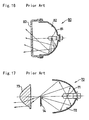
- FIGs. 15-17 illustrate configurations of a conventional automobile light or traffic light.
- a conventional automobile light 90 in Fig. 15 comprises a light source 91, a rotated parabolic surface reflector 92 having a focus on the light source 91, a front lens 93 having prismatic cuts 93a on its inner surface.
- Light emitted from the light source 91 is reflected by the rotated parabolic surface reflector 92 so as to form parallel light rays, then the reflected light is diffused by the prismatic cuts 93a when passing through the front lens 93, thereby a predetermined light distribution is obtained.
- Fig. 16 illustrates another conventional automobile light 80 in a horizontal cross sectional view after the light 80 has been assembled.
- the conventional automobile light 80 comprises a light source 81, a complex reflecting surface 82, and a front lens 83 without any prismatic cuts.
- the complex reflecting surface 82 is configured such that a parabola having a focus on the light source 81 exists in a vertical cross sectional view when the automobile light 80 is assembled, and that a complex paraboloidal solid surface appears to be a composition of connected straight lines in a horizontal cross sectional view.
- Light distribution pattern of the light 80 is basically formed by adjusting the complex reflecting surface 82.
- Fig. 17 illustrates still another conventional projection-type automobile light 70 comprising a light source 71, an aspherical lens 73, an ellipse group reflecting surface 72 having a first focus on the light source 71 and a second focus to which light reflected from the elliptical reflecting surface 72 converges.
- the focused image of light rays is projected to the aspherical lens 73 with enlargement.
- the light rays are refracted in the aspherical lens 73 when passing through.
- Light distribution patterns of the projection-type automobile light 70 are comprised of such light rays.
- a shade 74 may be used to prohibit unnecessary light rays to form light distribution patterns which are coming out from the aspherical lens 73.
- the top portion is located around the second focus of the elliptical reflecting surface 72.
- Multi projection lens type projection light which is disclosed in Japanese Patent Publication No. JP-B-0364962 (& JP-A-640 65 701 ) is an improvement of an original projection light.
- the conventional automobile lights or traffic lights described in the above have the following problems or deficiencies.
- the automobile light 90 in Fig. 15 is not able to provide an appearance with superior transparency of the front lens 93 and three dimensional feeling, i.e. an appreciation of the three-dimensional interior of the automobile light, which are becoming important requirements in the market.
- the prismatic cuts 93a must have optical function, and deep straight line cuts or curved line cuts with great curvature are required. Accordingly, the lens 93 has to be thick, and the transparency of the lens 93 is deteriorated.
- the automobile light 80 in Fig. 16 has superior transparency, because the lens 83 does not have any prismatic cuts. However, it is difficult to obtain sufficient width of a light distribution pattern by adjusting the complex reflecting surface 82, because the adjustment is required to elements of the complex reflecting surface, which are positioned at the deepest portion of the reflecting surface 82,while the light distribution patterns of the automobile light 80 must be basically determined by the combined reflecting surface 82.
- the projection-type automobile light 70 in Fig. 17 has a large depth to the extent of accompanying inconvenience on attachment of the light to an automobile body.
- an external diameter of the aspherical lens 73 is small, and light emitting area of the projection-type automobile light 70 is also small.
- visibility of the automobile incorporating the projection-type automobile light 70 is small from another vehicle traveling in an on-coming lane.
- the automobile lights 70, 80, 90 are commonly used in the market, and are lacking uniqueness and novelty of design. Furthermore, neither one of the automobile lights 70, 80, 90 is able to provide sufficient efficiency when depth of the light is reduced, because utilization efficiency of lumen output of a light source depends on a depth of the automobile light.
- the automobile lamp disclosed in Japanese Patent Publication No. JP-B-03-64962 has the following Problems or deficiencies. Since the optical axes of the respective aspherical lenses are in different directions to each other, the light distribution pattern of the automobile lamp must be formed by a combination of light distributions from each aspherical lens. Therefore, there is a tendency that connecting lines of the respective light distribution pattern of each aspherical lens appear clearly in the light distribution pattern of the automobile lamp.
- the second focus of the ellipse group reflecting surface and the focus of aspherical lens is a common dot.
- the radius of curvature of the aspherical lens is not the same as the radius of curvature of the ellipse.
- the aspherical lens is not located in a position in which the other presumed hemispherical portion of the ellipse of the ellipse group reflecting surface is located.
- the elliptical reflecting surface is extended towards the aspherical lens with an unchanged diameter of the aspherical lens, the amount of light incident to the aspherical lens 73 does not improve very much.
- the light rays reflected by the extended reflecting portion are not incident on the aspherical lens, because the focus of the aspherical lens is a dot.
- light rays reflected by the lower half portion of the reflector from the light source are not incident on the aspherical lens if the optical axes of the reflector and of the aspherical lens are parallel to each other, because the light rays reflected by that portion become upward light rays which are not necessary for the formation of passing-by light distribution patterns. If it is required to obtain larger amount of light, overall size of the projection-type automobile light must be enlarged.
- EP-A-0 854 316 which relates to a projector type lamp having a projection lens and a reflector
- the projection lens comprises a cylindrical lens portion which forms a center portion of the projection lens and whose vertical cross section has a curve when the projector type lamp is installed and aspherical lens portions which are halves of an aspherical lens and formed continuous to the respective right and left end portions of the cylindrical lens portion.
- the reflector is divided into four parts located in upper and lower sides and right and left sides thereof; an upper reflection surface, a lower reflection surface, a right reflection surface, and a left reflection surface, the four reflection surfaces being formed as curved surfaces on the basis of oval surfaces and combined together.
- the shape and area of the projection lens can be changed without losing the characteristics of the projector type lamp, while there are problems for the prior projector type lamp of lacking visibility of the projector type lamp from a vehicle running in an opposite direction and a passenger and design freedom, the front shape of the projection lens to be selected being only relatively small circles.
- the present invention is directed to a projection-type automobile headlight that substantially obviates one or more of the above problems due to the limitations and disadvantages of the related art.
- An object of the invention is to provide a projection-type automobile light having novel appearance with superior transparency of the front lens and three dimensional feeling, i.e. an appreciation of the three-dimensional interior of the automobile light.
- Another object of the invention is to provide a projection-type automobile light with sufficient light emitting area capable of providing horizontally wide and highly uniform light distribution patterns.
- Still another object of the invention is to provide a projection light with high incident efficiency of light rays being reflected by a reflecting surface on an aspherical lens.
- the projection-type automobile light 1 comprises a light source 2, a reflector 3 comprising a plurality of reflector units 31 (also called “reflecting units"), a front lens comprising a plurality of surrounding aspherical lenses 4 and a central aspherical lens 4' which correspond respectively to the plurality of reflector units 31 and a holder portion 4a which connects respective aspherical lenses 4 and determines a perimeter of the front lens.
- the reflector 3 is a combination of six reflector units 31.
- a shade plate comprising a central shade 5' and a plurality of surrounding shades 5 may be interposed between the reflector 3 and the front lens for prohibiting unnecessary light rays on formation of light distribution pattern of the projection-type automobile light 1.
- the shade plate is transparent except for the central shade 5' and the plurality of shades 5.
- a central reflector unit 6 having a focus F3 in a predetermined position may be interposed between the reflector 3 and the outer lens such that the central reflector unit 6 corresponds to a central shade 5' (if the shade 5 or 5' is necessary) and to a central aspherical lens 4'.
- Optical axes of the aspherical lenses 4 and 4' is parallel to an optical axis X of the projection-type automobile light 1.
- the aspherical lenses 4 and 4' are arranged such that the aspherical lenses 4 radiates from the central aspherical lens 4'.
- Each surrounding aspherical lens 4 is located 10-200mm outside of the central spherical lens 4' with a focal distance of 10-60 mm.
- the reflector unit 31 has an ellipse group reflecting surface. In this embodiment, the reflector unit 31 has a rotated elliptical surface. Each reflector unit 31 has a common first focus F1 around the light source 2, and has a respective second focus F2 on an optical axis Z of a corresponding ashperical lens 4, typically on the focus of the corresponding aspherical lens 4. As shown in Fig. 2 , each reflector unit 31 has an optical axis Y with an angle ⁇ of 10-80°related to an optical axis X of the projection-type automobile light 1. The central reflector unit 6 is located such that the central reflector unit 6 does not prohibit light rays from traveling to the reflector unit 31. Other configurations of the projection-type automobile light 1 are substantially the same as the one of the conventional projection-type automobile light 70.
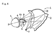
- Fig. 4 illustrates a basic configuration of the reflector unit 31.
- the curved line A-B-C corresponds to second focus of the reflector unit 31, and also corresponds to focus of aspherical lens 4 corresponding to what we call "curvature of field" depending on an incident angle.
- Light rays incident parallel to the optical axis Z of the aspherical lens 4 focus to a center point B of the curved line A-B-C.
- the light rays focus to a closer point to the aspherical lens 4 than the point B.
- the focus of the aspherical lens 4 moves from B to A or B to C, depending on incident angle and position of light rays relative to the optical axis Z of the aspherical lens 4.
- the second focus of the reflecting surface is the point B located at the center of an upper end of the shade 74.
- the second focus F2 of the reflector unit 31 is the curved line A-B-C which more precisely corresponds to the movement of the focus F4 position of the aspherical lens 4 depending on the reflecting position of the light rays on the reflector unit 31.
- Light rays reflected on the right side in front view of the reflector unit 31 focus around the point C of the curved line A-B-C.
- Light rays reflected around the center of the reflector unit 31 focus around the point B.
- the shades 5 and a central shade 5' may be curved along the second focus line A-B-C of the reflector unit 31 which is also the focus F4 of the aspherical lens 4.
- An upper end of the shade 5 or 5' lies along the curved line A-B-C.
- the projection-type automobile light 1 of the present invention superior utilization efficiency of lumen output from the light source 2 is achieved.
- directions of the optical axes Y and Z between the reflector or reflecting unit 31 and the aspherical lens 4 differ to each other, whereas the directions of optical axes of the reflector 71 and the aspherical lens 73 are substantially the same in conventional projection-type automobile lights 70.
- the optical axes Z of the aspherical lenses 4 and 4' are parallel to the optical axis X of the projection-type automobile light 1.
- the optical axes Z of the ashperical lenses 4 surrounding the central aspherical lens 4' are inclined inward of the corresponding reflector unit 31 relative to the optical axes Y of the reflector unit 31. Therefore, light rays reflected by the the reflector unit 31 positioned below a horizontal center line of the reflector 3 can be incident to the particular aspherical lens 4.
- the number of light rays reflected to the above of a horizontal center line of the reflector 3 is small compared to a conventional projection-type automobile light 70.
- the additional reflecting area directly results in an improvement of utilization efficiency of lumen output of the light source 2, because the focus F4 of the aspherical lens 4 is a curved line focus and it is able to adjust radius of curvature of the extended portion such that the light rays reflected by said portion can be incident to the aspherical lens4.
- the entire shape of the reflector unit 31 looks like an elliptical reflecting surface. However, precisely, the entire shape of the reflector unit 31 is a free-curved surface. Therefore the adjustment of the radius of curvature is achieved.
- reflected light rays incident to the aspherical lens 4 is improved to such an extend that it is possible to reduce the depth of the projection-type automobile light in comparison with conventional projection-type automobile light 70.
- reflected light rays after having been focused around respective second focus on a curved line A-B-C travel towards a center of the corresponding aspherical lens 4 and cross each other in the vicinity of the corresponding aspherical lens 4, because the second focus A-B-C of the reflector unit 31 is designed to correspond to the shift or the movement of the focus F4 of the aspherical lens 4 depending the angles of the incident light with the aspherical lens 4. Accordingly, a larger amount of light being incident to the aspherical lens 4 is obtained.
- the front lens of the projection-type automobile light 1 comprises a plurality of aspherical lenses 4. Since each aspherical lens 4 is configured to provide light passages described in the above, the projection-type automobile light 1, wherein having the front lens comprises a plurality of aspherical lenses 4, achieves improved utilization efficiency of lumen output from the light source 2 as compared with a projection-type automobile light having a single aspherical lens 4.
- Light distribution patterns of the projection-type automobile light 1 have superior uniformity of luminous density distribution, and boundaries among light distribution pattern elements, which are formed by light emitted from respective aspherical lenses 4, are not conspicuous. Since optical axes Z of respective aspherical lenses 4 are parallel to the optical axis X of the projection-type automobile light 1, the light distribution pattern of the projection-type automobile light 1 is a combination of a plurality of the same light distribution pattern elements which are formed by light emitted from respective aspherical lenses 4. Therefore, it is relatively easy to adjust design parameters for formation of light distribution patterns as compared to a conventional projection-type automobile light having an outer lens comprising a plurality of aspherical lens with optical axes in different directions as disclosed in Japanese Patent Publication No. JP-B-03-64962 .
- the shade 5 is used to prohibit unnecessary light rays to form a light distribution pattern when passing by another vehicle. It is well known that a shade is used in projection lights to form the passing-by light distribution pattern.
- the shade 74 prohibits light rays which are reflected upwards by a lower half portion of the rotated elliptical surface reflector 72.
- the shade 5 or 5' is disposed in order to prohibit upwards reflected light rays to form a passing-by light distribution pattern.
- the shade 5 or 5' may be disposed only for the aspherical lenses 4 in a lower half portion of the front lens. Actually, it is preferrable to arrange the shade 5 for aspherical lenses 4 in an upper half portion of the front lens in order to prohibit upward light rays to be reflected by the deepest portion of the reflector 3. In an alternative way, the shade 5 or 5' may be disposed for respective aspherical lens 4 or 4' as shown in Fig. 1 . However, even though the shade 5 or 5' are not used, a light distribution pattern with acceptable level quality is obtained and the utilized light amount of the light source 2 is greatly improved.
- the aspherical lens 4 and 4' may be colored to comply with the color requirement of the projection-type automobile light 1 depending on its usage.
- a colored cap 7 may be disposed to cover the light source 2 as in Fig. 2 .
- the projection-type automobile light 1 may further comprise an extension 8 which covers the outer lens except for aspherical lens 4 and 4' as in Fig. 2 .
- Perimeter of the extension 8 is designed to fit to an automobile body.
- the extension 8 has the same color as the automobile body, or may be coated to have metallic shine. The color or metallic shine of the extension 8 is reflected in the aspherical lens 4, which improves aesthetic appearance of the projection-type automobile light 1.
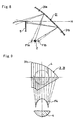
- Fig. 5 illustrates a light distribution pattern DU obtained only by an aspherical lens 4 located in an upper right portion in front view of the outer lens of the projection-type automobile light 1 (The location of the aspherical lens 4 is illustrated at the right lower corner of Fig. 5 ).
- a horizontally large light distribution is obtained by adopting a free-curved reflecting surface for the reflector unit 31 corresponding to the aspherical lens 4 in the upper right portion.
- Fig. 6 illustrates a light distribution pattern DH obtained only by an aspherical lens 4 located in a horizontal right portion in front view of the outer lens of the projection-type automobile light 1 (The location of the aspherical lens 4 is illustrated at the right lower corner of the Fig. 6 ).
- the reflector unit 31 corresponding to the aspherical lens 4 at the horizontal right side is a rotated elliptic surface and is designed to have high luminance at a center portion of the light distribution pattern DH.
- Fig. 7 illustrates a light distribution pattern DT of the projection-type automobile light 1 which is a combined light distribution pattern of the patterns of the respective aspherical lenses 4 and 4'. Since the reflector 3 is a combination of a plurality of reflector units 31 having different shapes depending on their assigned position, the light distribution pattern DT has a wide illumination area and a high luminance at its center portion.
- each reflector unit 31 is divided by a horizontal surface H passing through a center of its corresponding lens 4 into an upper reflecting surface 31 a and a lower reflecting surface 31b.
- the first focus F1a of the upper reflecting surface 31a is in front of a light source 2.
- the first focus F1b of the lower reflecting surface 31b is in the rear of the light source 2.
- the upper reflecting surface 31 a reflects light rays from the light source 2 downward to make an image of the light source 2 above the horizontal surface H.
- the lower reflecting surface 31b reflects light rays from the light source 2 upward to make an image of the light source 2 below the horizontal surface H.
- a shade 5 is able to more effectively prohibit only upward light rays when forming the passing-by light distribution pattern.
- the light distribution pattern obtained by the second preferred embodiment has a larger utilization efficiency of light emitted from the light source 2 and a superior quality with reduced upward reflected light rays.
- Fig. 9 illustrates essential parts of a third preferred embodiment of the present invention.
- each reflector unit 31 is divided into a plurality of segments 31c along vertical lines.
- Each segment 31c has a second focus whose position is consistent with a corresponding focus of the aspherical lens 4.
- a segment 31 located on a right end in front view of the reflector unit 31 has a second focus on a right end of a curved line focus F4 of the aspherical lens 4.
- each segment 31c is designed to have the second focus to make an image of the light source 2 above a horizontal surface H passing through a center of the corresponding aspherical lens 4. Since the reflector unit 31 is divided into the segments 31, it facilitates to determine the position of the second focus of the reflector unit 31. This configuration provides accurate and easier product design.
- Fig. 10 illustrates a design not falling under the scope of the claims.
- the projection-type automobile light generally has the tendency that the reflecting surface above the optical axis Z of a aspherical lens 4 reflects light rays to be downward light of the projection-type automobile light 1 and that reflecting surface below an optical axis Z of a aspherical lens 4 reflects light rays to be upward light of the projection-type automobile light 1.
- a reflector unit 31 below the optical axis of the projection-type automobile light X may be a rotated parabolic surface 32 which substantially reflects light rays to be downward light of the projection-type automobile light 1.
- An outer lens portion corresponding to the rotated parabolic surface 32 may be a flat lens portion 9 with prismatic cuts.
- Figs. 11-13 illustrate essential parts of the fourth to six preferred embodiments of the preferred invention.
- the aspherical lenses 4 or 4' are not limited to convex lenses. Instead of the convex lenses, a Fresnel lens 41 (41') in Fig. 11 may be used.
- a transformed aspherical lens 42 comprising a center convex lens portion 42a and a surrounding Fresnel lens portion 42b is also acceptable instead of the aspherical lens 4 or 4'.
- the Fresnel lens 41 (41') and the transformed aspherical lens 42(42') provide a novel design. Conventional projection lights have projection lens portions which have a considerable thickness to the outside front.
- the Fresnel lens 41 (41') and the transformed aspherical lens 42(42') are thin.
- the Fresnel lens 41 (41') and the transformed aspherical lens 42(42') are able to provide aesthetic appearance like crystal glass by adjusting pitches of the Fresnel cuts.
- the projection lens is made to be flat by adopting Fresnel lens 41 (41'), one is able to reduce the possibility of the occurrence of unfavorable deformation of the outer lens during production process involving resin molding.
- Fig. 13 illustrates another transformed aspherical lens 43 (43') comprising a cylindrical lens portion 43c and half lens portions 43a and 43b respectively attached from both sides of the cylindrical lens portion 43c.
- the half lens portions 43a and 43b are comprised of divided half along its central axis of the aspherical lens 4 or 4' in the first preferred embodiment.
- Luminous flux comprising light rays reflected by the rotated elliptic surface reflector unit 31 is circular in a vertical cross sectional view.
- the luminous flux is enlarged to both right and left sides along the central axis W of the cylindrical lens portion 43.
- a horizontally wide light distribution pattern is obtained by arranging the transformed aspherical lens 43 such that the central axis W of the cylindrical lens portion 43c is horizontal.
- Fig. 14 illustrates a design not falling under the scope of the claims.
- This configuration is able to reduce overall depth of the projection-type automobile light 1 without producing any unfavorable substantial effects in the light distribution of the projection-type automobile light 1.
- the reflector unit 31 is a rotated elliptic surface 31 with small curvature, and the aperture of the reflector unit 31 is large.
- An opening end of the bulb of the light source 2 which is not inserted in a socket faces towards a corresponding reflector unit 31.
- the light source 2 is attached from a front side of the projection-type automobile light 1 in case that neither the central aspherical lens 4' nor the central reflector unit 6 are necessary.
- the projection-type automobile light since the front lens of the projection-type automobile light comprises a plurality of aspherical lenses, the projection-type automobile light is able to provide a novel design when the projection-type automobile light is both lit and off. This novel design emphasizes differences from conventional projection-type automobile light, and results in attracting attention on the market. Additionally, the outer lens comprising the aspherical lenses and the holder portion which connects respective aspherical lenses 4 and determines a perimeter of the outer lens also provides new appearance of the projection-type automobile light. A wide variety of appearances is obtained by slightly changing outer lens design.
- the appearance of the projection-type automobile light is comprised of mixture of enlarged and actual-size images of the interior of the reflector.
- the images from the aspherical lenses are enlarged, while the ones from the holder portion have the size thereof.
- the lens holder portion is designed to be opaque and the shade is designed to have a color matching the automobile body color
- the projection-type automobile light 1 is able to have different colors depending on whether the light is lit or off.
- an outer lens has Fresnel cuts with small pitches, the projection-type automobile light is able to have an appearance like crystal glass.
- the reflector is a combination of reflector units each having an ellipse group reflecting surface whose optical axis Y is inclined to the outside of the reflector relative to the optical axis X of the projection type automobile light
- the reflector is shallow and projection-type automobile light having such a reflector is thinner than conventional ones.
- This configuration reduces required space for a projection-type automobile light in an automobile body.
- each aspherical lens has lower temperature than conventional one. Therefore, it is possible to form the outer lens comprising a plurality of aspherical lenses of plastic resin, which leads to great production cost reduction of the projection-type automobile light.
Landscapes
- Engineering & Computer Science (AREA)
- General Engineering & Computer Science (AREA)
- Non-Portable Lighting Devices Or Systems Thereof (AREA)
Description
- The present invention relates to a configuration of a projection light used for illumination or signaling functions, more particularly to a configuration of an automobile light such as a headlight, a fog light, a tail light, and turn signal light (indicator), or a traffic light for a driving road and a railroad. The projection light is generally circular in front view and comprising a light source, an ellipse group reflecting surface and a thick front lens, and whose light distribution is basically determined upon a principle of projection of a focused image and is comprised of the following light rays: the light rays being emitted from the light source and reflected by the reflector, being focused to at least one point, then being projected to and traveling through the thick circular front lens.
-
Figs. 15-17 illustrate configurations of a conventional automobile light or traffic light. Aconventional automobile light 90 inFig. 15 comprises alight source 91, a rotatedparabolic surface reflector 92 having a focus on thelight source 91, afront lens 93 havingprismatic cuts 93a on its inner surface. - Light emitted from the
light source 91 is reflected by the rotatedparabolic surface reflector 92 so as to form parallel light rays, then the reflected light is diffused by theprismatic cuts 93a when passing through thefront lens 93, thereby a predetermined light distribution is obtained. -
Fig. 16 illustrates anotherconventional automobile light 80 in a horizontal cross sectional view after thelight 80 has been assembled. Theconventional automobile light 80 comprises alight source 81, a complex reflectingsurface 82, and afront lens 83 without any prismatic cuts. The complex reflectingsurface 82 is configured such that a parabola having a focus on thelight source 81 exists in a vertical cross sectional view when theautomobile light 80 is assembled, and that a complex paraboloidal solid surface appears to be a composition of connected straight lines in a horizontal cross sectional view. Light distribution pattern of thelight 80 is basically formed by adjusting thecomplex reflecting surface 82. -
Fig. 17 illustrates still another conventional projection-type automobile light 70 comprising alight source 71, anaspherical lens 73, an ellipsegroup reflecting surface 72 having a first focus on thelight source 71 and a second focus to which light reflected from the elliptical reflectingsurface 72 converges. The focused image of light rays is projected to theaspherical lens 73 with enlargement. The light rays are refracted in theaspherical lens 73 when passing through. Light distribution patterns of the projection-type automobile light 70 are comprised of such light rays. - A
shade 74 may be used to prohibit unnecessary light rays to form light distribution patterns which are coming out from theaspherical lens 73. When theshade 74 is used, the top portion is located around the second focus of the elliptical reflectingsurface 72. Multi projection lens type projection light which is disclosed inJapanese Patent Publication No. JP-B-0364962 JP-A-640 65 701 - The conventional automobile lights or traffic lights described in the above have the following problems or deficiencies. The
automobile light 90 inFig. 15 is not able to provide an appearance with superior transparency of thefront lens 93 and three dimensional feeling, i.e. an appreciation of the three-dimensional interior of the automobile light, which are becoming important requirements in the market. Theprismatic cuts 93a must have optical function, and deep straight line cuts or curved line cuts with great curvature are required. Accordingly, thelens 93 has to be thick, and the transparency of thelens 93 is deteriorated. - The
automobile light 80 inFig. 16 has superior transparency, because thelens 83 does not have any prismatic cuts. However, it is difficult to obtain sufficient width of a light distribution pattern by adjusting thecomplex reflecting surface 82, because the adjustment is required to elements of the complex reflecting surface, which are positioned at the deepest portion of the reflectingsurface 82,while the light distribution patterns of theautomobile light 80 must be basically determined by the combined reflectingsurface 82. - The projection-
type automobile light 70 inFig. 17 has a large depth to the extent of accompanying inconvenience on attachment of the light to an automobile body. On the other hand, an external diameter of theaspherical lens 73 is small, and light emitting area of the projection-type automobile light 70 is also small. When the projection-type automobile light 70 is used as a headlight, visibility of the automobile incorporating the projection-type automobile light 70 is small from another vehicle traveling in an on-coming lane. - The
automobile lights automobile lights Japanese Patent Publication No. JP-B-03-64962 aspherical lens 73 does not improve very much. The light rays reflected by the extended reflecting portion are not incident on the aspherical lens, because the focus of the aspherical lens is a dot. Aditionally, light rays reflected by the lower half portion of the reflector from the light source are not incident on the aspherical lens if the optical axes of the reflector and of the aspherical lens are parallel to each other, because the light rays reflected by that portion become upward light rays which are not necessary for the formation of passing-by light distribution patterns. If it is required to obtain larger amount of light, overall size of the projection-type automobile light must be enlarged. - Further attention is drawn to the document
EP-A-0 854 316 , which relates to a projector type lamp having a projection lens and a reflector, wherein the projection lens comprises a cylindrical lens portion which forms a center portion of the projection lens and whose vertical cross section has a curve when the projector type lamp is installed and aspherical lens portions which are halves of an aspherical lens and formed continuous to the respective right and left end portions of the cylindrical lens portion. The reflector is divided into four parts located in upper and lower sides and right and left sides thereof; an upper reflection surface, a lower reflection surface, a right reflection surface, and a left reflection surface, the four reflection surfaces being formed as curved surfaces on the basis of oval surfaces and combined together. Therefore, the shape and area of the projection lens can be changed without losing the characteristics of the projector type lamp, while there are problems for the prior projector type lamp of lacking visibility of the projector type lamp from a vehicle running in an opposite direction and a passenger and design freedom, the front shape of the projection lens to be selected being only relatively small circles. - In accordance with the present invention, a projection-type automobile light, as set forth in
claim 1, is provided. Further embodiments are claimed in the dependent claims. - The present invention is directed to a projection-type automobile headlight that substantially obviates one or more of the above problems due to the limitations and disadvantages of the related art.
- An object of the invention is to provide a projection-type automobile light having novel appearance with superior transparency of the front lens and three dimensional feeling, i.e. an appreciation of the three-dimensional interior of the automobile light.
- Another object of the invention is to provide a projection-type automobile light with sufficient light emitting area capable of providing horizontally wide and highly uniform light distribution patterns.
- Still another object of the invention is to provide a projection light with high incident efficiency of light rays being reflected by a reflecting surface on an aspherical lens.
- Additional objects and advantages of the invention will be set forth in part in the description which follows, and in part will be obvious from the description, or may be learned by practice of the invention. The objects and advantages of the invention will be realized and attained by means of the elements and combinations particularly pointed out in the appended claims.
- It is to be understood that both, theforegoing general description and the following detailed description, are exemplary and explanatory and are intended to provide further explanation of the invention as claimed.
- The accompanying drawings, which are incorporated in and constitute a part of this specification, illustrate several embodiments of the invention and together with the description, serve to explain the principles of the invention.
-
Fig. 1 illustrates an exploded perspective view a first preferred embodiment of the present invention. -
Fig. 2 illustrates a cross sectional view of the first preferred embodiment of the present invention along the A-A line inFig. 1 . -
Fig. 3 illustrates a front view of the first preferred embodiment of the present invention. -
Fig. 4 illustrates a perspective view showing essential parts of the first preferred embodiment of the present invention. -
Fig. 5 illustrates a graph showing light distribution characteristics of a projection-type automobile light from an aspherical lens on an upper right portion of the projection-type automobile light according to the first preferred embodiment of the present invention. -
Fig. 6 illustrates a graph showing light distribution characteristics of a projection-type automobile light from an aspherical lens on a central right end of the projection-type automobile light according to the first preferred embodiment of the present invention. -
Fig. 7 illustrates a graph showing light distribution characteristics of a projection-type automobile light as a whole according to the first preferred embodiment of the present invention. -
Fig. 8 illustrates cross sectional view showing essential parts of a second preferred embodiment of the present invention. -
Fig. 9 illustrates a cross sectional view showing essential parts of a third preferred embodiment of the present invention. -
Fig. 10 illustrates a cross sectional view showing essential parts of a design not falling under the scope of the claims. -
Fig. 11 illustrates a cross sectional view showing essential parts of a fourth preferred embodiment of the present invention. -
Fig. 12 illustrates a cross sectional view showing essential parts of a fifth preferred embodiment of the present invention. -
Fig. 13 illustrates a cross sectional view showing essential parts of a sixth preferred embodiment of the present invention. -
Fig. 14 illustrates a cross sectional view showing essential parts of a design not falling under the scope of the claims. -
Fig. 15 illustrates a cross sectional view showing a conventional automobile light. -
Fig. 16 illustrates a cross sectional view showing another conventional automobile light. -
Fig. 17 illustrates a cross sectional view showing still another conventional projection-type automobile light. - Reference will now be made in detail to the preferred embodiments of the present invention. Whenever possible, the same references numbers will be used throughout the drawings to refer to the same or like parts.
-
Figs. 1-4 illustrate a first preferred embodiment of the present invention. The projection-type automobile light 1 comprises alight source 2, areflector 3 comprising a plurality of reflector units 31 (also called "reflecting units"), a front lens comprising a plurality of surrounding aspherical lenses 4 and a central aspherical lens 4' which correspond respectively to the plurality ofreflector units 31 and aholder portion 4a which connects respective aspherical lenses 4 and determines a perimeter of the front lens. In this embodiment, thereflector 3 is a combination of sixreflector units 31. When the projection-type automobile light 1 is used for a headlight, or if necessary for any other reason, a shade plate comprising a central shade 5' and a plurality of surroundingshades 5 may be interposed between thereflector 3 and the front lens for prohibiting unnecessary light rays on formation of light distribution pattern of the projection-type automobile light 1. The shade plate is transparent except for the central shade 5' and the plurality ofshades 5. - Furthermore, in order to improve utilization efficiency of lumen output from the
light source 2, a central reflector unit 6 having a focus F3 in a predetermined position may be interposed between thereflector 3 and the outer lens such that the central reflector unit 6 corresponds to a central shade 5' (if theshade 5 or 5' is necessary) and to a central aspherical lens 4'. - Optical axes of the aspherical lenses 4 and 4' is parallel to an optical axis X of the projection-
type automobile light 1. The aspherical lenses 4 and 4' are arranged such that the aspherical lenses 4 radiates from the central aspherical lens 4'. Each surrounding aspherical lens 4 is located 10-200mm outside of the central spherical lens 4' with a focal distance of 10-60 mm. - The
reflector unit 31 has an ellipse group reflecting surface. In this embodiment, thereflector unit 31 has a rotated elliptical surface. Eachreflector unit 31 has a common first focus F1 around thelight source 2, and has a respective second focus F2 on an optical axis Z of a corresponding ashperical lens 4, typically on the focus of the corresponding aspherical lens 4. As shown inFig. 2 , eachreflector unit 31 has an optical axis Y with an angle α of 10-80°related to an optical axis X of the projection-type automobile light 1. The central reflector unit 6 is located such that the central reflector unit 6 does not prohibit light rays from traveling to thereflector unit 31. Other configurations of the projection-type automobile light 1 are substantially the same as the one of the conventional projection-type automobile light 70. -
Fig. 4 illustrates a basic configuration of thereflector unit 31. The curved line A-B-C corresponds to second focus of thereflector unit 31, and also corresponds to focus of aspherical lens 4 corresponding to what we call "curvature of field" depending on an incident angle. Light rays incident parallel to the optical axis Z of the aspherical lens 4 focus to a center point B of the curved line A-B-C. As light rays incident at a larger angle relative to the optical axis Z of the aspherical lens 4, the light rays focus to a closer point to the aspherical lens 4 than the point B. The focus of the aspherical lens 4 moves from B to A or B to C, depending on incident angle and position of light rays relative to the optical axis Z of the aspherical lens 4. - In a conventional automobile projection light 70 (
fig 17 ) having an ellipse group reflecting surface, the second focus of the reflecting surface is the point B located at the center of an upper end of theshade 74. On the other hand, in the projection-type automobile light 1 of the present invention, the second focus F2 of thereflector unit 31 is the curved line A-B-C which more precisely corresponds to the movement of the focus F4 position of the aspherical lens 4 depending on the reflecting position of the light rays on thereflector unit 31. Light rays reflected on the right side in front view of thereflector unit 31 focus around the point C of the curved line A-B-C. Light rays reflected around the center of thereflector unit 31 focus around the point B. And light rays reflected on the left side in front view of thereflector unit 31 focus around the point A. Theshades 5 and a central shade 5', if necessary, may be curved along the second focus line A-B-C of thereflector unit 31 which is also the focus F4 of the aspherical lens 4. An upper end of theshade 5 or 5' lies along the curved line A-B-C. - In the projection-
type automobile light 1 of the present invention, superior utilization efficiency of lumen output from thelight source 2 is achieved. With respect to light passage in the projection-type automobile light 1 in a vertical cross section, as shownFig. 2 , directions of the optical axes Y and Z between the reflector or reflectingunit 31 and the aspherical lens 4 differ to each other, whereas the directions of optical axes of thereflector 71 and theaspherical lens 73 are substantially the same in conventional projection-type automobile lights 70. The optical axes Z of the aspherical lenses 4 and 4' are parallel to the optical axis X of the projection-type automobile light 1. Accordingly, the optical axes Z of the ashperical lenses 4 surrounding the central aspherical lens 4' are inclined inward of thecorresponding reflector unit 31 relative to the optical axes Y of thereflector unit 31. Therefore, light rays reflected by the thereflector unit 31 positioned below a horizontal center line of thereflector 3 can be incident to the particular aspherical lens 4. The number of light rays reflected to the above of a horizontal center line of thereflector 3 is small compared to a conventional projection-type automobile light 70. If the reflectingunit 31 is extended to the aspherical lens 4 and the diameter of the aspherical lens 4 is unchanged, the additional reflecting area directly results in an improvement of utilization efficiency of lumen output of thelight source 2, because the focus F4 of the aspherical lens 4 is a curved line focus and it is able to adjust radius of curvature of the extended portion such that the light rays reflected by said portion can be incident to the aspherical lens4. The entire shape of thereflector unit 31 looks like an elliptical reflecting surface. However, precisely, the entire shape of thereflector unit 31 is a free-curved surface. Therefore the adjustment of the radius of curvature is achieved. Furthermore, efficiency of reflected light rays incident to the aspherical lens 4 is improved to such an extend that it is possible to reduce the depth of the projection-type automobile light in comparison with conventional projection-type automobile light 70.With respect to light passage in the projection-type automobile light 1 in a horizontal cross section, reflected light rays after having been focused around respective second focus on a curved line A-B-C, travel towards a center of the corresponding aspherical lens 4 and cross each other in the vicinity of the corresponding aspherical lens 4, because the second focus A-B-C of thereflector unit 31 is designed to correspond to the shift or the movement of the focus F4 of the aspherical lens 4 depending the angles of the incident light with the aspherical lens 4. Accordingly, a larger amount of light being incident to the aspherical lens 4 is obtained. - The front lens of the projection-
type automobile light 1 comprises a plurality of aspherical lenses 4. Since each aspherical lens 4 is configured to provide light passages described in the above, the projection-type automobile light 1, wherein having the front lens comprises a plurality of aspherical lenses 4, achieves improved utilization efficiency of lumen output from thelight source 2 as compared with a projection-type automobile light having a single aspherical lens 4. - Light distribution patterns of the projection-
type automobile light 1 have superior uniformity of luminous density distribution, and boundaries among light distribution pattern elements, which are formed by light emitted from respective aspherical lenses 4, are not conspicuous. Since optical axes Z of respective aspherical lenses 4 are parallel to the optical axis X of the projection-type automobile light 1, the light distribution pattern of the projection-type automobile light 1 is a combination of a plurality of the same light distribution pattern elements which are formed by light emitted from respective aspherical lenses 4. Therefore, it is relatively easy to adjust design parameters for formation of light distribution patterns as compared to a conventional projection-type automobile light having an outer lens comprising a plurality of aspherical lens with optical axes in different directions as disclosed inJapanese Patent Publication No. JP-B-03-64962 - The
shade 5 is used to prohibit unnecessary light rays to form a light distribution pattern when passing by another vehicle. It is well known that a shade is used in projection lights to form the passing-by light distribution pattern. In the conventional projection-type automobile light 70, theshade 74 prohibits light rays which are reflected upwards by a lower half portion of the rotatedelliptical surface reflector 72. In the projection-type automobile light 1 of the present invention, theshade 5 or 5' is disposed in order to prohibit upwards reflected light rays to form a passing-by light distribution pattern. Since thereflector unit 31 in the upper half portion of thereflector 3 does not reflect light rays upward, theshade 5 or 5' may be disposed only for the aspherical lenses 4 in a lower half portion of the front lens. Actually, it is preferrable to arrange theshade 5 for aspherical lenses 4 in an upper half portion of the front lens in order to prohibit upward light rays to be reflected by the deepest portion of thereflector 3. In an alternative way, theshade 5 or 5' may be disposed for respective aspherical lens 4 or 4' as shown inFig. 1 . However, even though theshade 5 or 5' are not used, a light distribution pattern with acceptable level quality is obtained and the utilized light amount of thelight source 2 is greatly improved. - Since light of
light source 2 is emitted through the plurality of aspherical lenses 4 and 4', the amount of light which passes through each aspherical lens 4 is greatly reduced as compared to conventional projection-type automobile light 70 whose outer lens is a singleaspherical lens 73 . Whereas it is impossible to form theaspherical lens 73 of plastic resin in theconventional projection light 70 because of a heat resistivity problem, it is possible to form the outer lens comprising the plurality of aspherical lense 4 and 4' and aholder portion 4a, by resin molding as a single unit. - The aspherical lens 4 and 4' may be colored to comply with the color requirement of the projection-
type automobile light 1 depending on its usage. In an alternative way to vary light color of the projection-type automobile light 1, a colored cap 7 may be disposed to cover thelight source 2 as inFig. 2 . - The projection-
type automobile light 1 may further comprise an extension 8 which covers the outer lens except for aspherical lens 4 and 4' as inFig. 2 . Perimeter of the extension 8 is designed to fit to an automobile body. The extension 8 has the same color as the automobile body, or may be coated to have metallic shine. The color or metallic shine of the extension 8 is reflected in the aspherical lens 4, which improves aesthetic appearance of the projection-type automobile light 1. -
Fig. 5 illustrates a light distribution pattern DU obtained only by an aspherical lens 4 located in an upper right portion in front view of the outer lens of the projection-type automobile light 1 (The location of the aspherical lens 4 is illustrated at the right lower corner ofFig. 5 ). A horizontally large light distribution is obtained by adopting a free-curved reflecting surface for thereflector unit 31 corresponding to the aspherical lens 4 in the upper right portion. -
Fig. 6 illustrates a light distribution pattern DH obtained only by an aspherical lens 4 located in a horizontal right portion in front view of the outer lens of the projection-type automobile light 1 (The location of the aspherical lens 4 is illustrated at the right lower corner of theFig. 6 ). Thereflector unit 31 corresponding to the aspherical lens 4 at the horizontal right side is a rotated elliptic surface and is designed to have high luminance at a center portion of the light distribution pattern DH. -
Fig. 7 illustrates a light distribution pattern DT of the projection-type automobile light 1 which is a combined light distribution pattern of the patterns of the respective aspherical lenses 4 and 4'. Since thereflector 3 is a combination of a plurality ofreflector units 31 having different shapes depending on their assigned position, the light distribution pattern DT has a wide illumination area and a high luminance at its center portion. -
Fig. 8 illustrates essential parts of the second preferred embodiment of the present invention. In this embodiment, eachreflector unit 31 is divided by a horizontal surface H passing through a center of its corresponding lens 4 into anupper reflecting surface 31 a and a lower reflectingsurface 31b. The first focus F1a of the upper reflectingsurface 31a is in front of alight source 2. The first focus F1b of the lower reflectingsurface 31b is in the rear of thelight source 2. Theupper reflecting surface 31 a reflects light rays from thelight source 2 downward to make an image of thelight source 2 above the horizontal surface H. The lower reflectingsurface 31b reflects light rays from thelight source 2 upward to make an image of thelight source 2 below the horizontal surface H. Therefore, ashade 5 is able to more effectively prohibit only upward light rays when forming the passing-by light distribution pattern. The light distribution pattern obtained by the second preferred embodiment has a larger utilization efficiency of light emitted from thelight source 2 and a superior quality with reduced upward reflected light rays. -
Fig. 9 illustrates essential parts of a third preferred embodiment of the present invention. In this embodiment, eachreflector unit 31 is divided into a plurality ofsegments 31c along vertical lines. Eachsegment 31c has a second focus whose position is consistent with a corresponding focus of the aspherical lens 4. For example, asegment 31 located on a right end in front view of thereflector unit 31 has a second focus on a right end of a curved line focus F4 of the aspherical lens 4. Additionally, similarly to the second preferred embodiment, eachsegment 31c is designed to have the second focus to make an image of thelight source 2 above a horizontal surface H passing through a center of the corresponding aspherical lens 4. Since thereflector unit 31 is divided into thesegments 31, it facilitates to determine the position of the second focus of thereflector unit 31. This configuration provides accurate and easier product design. -
Fig. 10 illustrates a design not falling under the scope of the claims. The projection-type automobile light generally has the tendency that the reflecting surface above the optical axis Z of a aspherical lens 4 reflects light rays to be downward light of the projection-type automobile light 1 and that reflecting surface below an optical axis Z of a aspherical lens 4 reflects light rays to be upward light of the projection-type automobile light 1. When the projection-type automobile light 1 is used only to form passing-by light distribution pattern, areflector unit 31 below the optical axis of the projection-type automobile light X may be a rotatedparabolic surface 32 which substantially reflects light rays to be downward light of the projection-type automobile light 1. An outer lens portion corresponding to the rotatedparabolic surface 32 may be a flat lens portion 9 with prismatic cuts. -
Figs. 11-13 illustrate essential parts of the fourth to six preferred embodiments of the preferred invention. The aspherical lenses 4 or 4' are not limited to convex lenses. Instead of the convex lenses, a Fresnel lens 41 (41') inFig. 11 may be used. A transformedaspherical lens 42 comprising a centerconvex lens portion 42a and a surroundingFresnel lens portion 42b is also acceptable instead of the aspherical lens 4 or 4'. The Fresnel lens 41 (41') and the transformed aspherical lens 42(42') provide a novel design. Conventional projection lights have projection lens portions which have a considerable thickness to the outside front. On the other hand, the Fresnel lens 41 (41') and the transformed aspherical lens 42(42') are thin. The Fresnel lens 41 (41') and the transformed aspherical lens 42(42') are able to provide aesthetic appearance like crystal glass by adjusting pitches of the Fresnel cuts. Furthermore, since the projection lens is made to be flat by adopting Fresnel lens 41 (41'), one is able to reduce the possibility of the occurrence of unfavorable deformation of the outer lens during production process involving resin molding. -
Fig. 13 illustrates another transformed aspherical lens 43 (43') comprising acylindrical lens portion 43c andhalf lens portions cylindrical lens portion 43c. Thehalf lens portions surface reflector unit 31 is circular in a vertical cross sectional view. When the light rays pass through thecylindrical lens portion 43c, the luminous flux is enlarged to both right and left sides along the central axis W of thecylindrical lens portion 43. A horizontally wide light distribution pattern is obtained by arranging the transformedaspherical lens 43 such that the central axis W of thecylindrical lens portion 43c is horizontal. -
Fig. 14 illustrates a design not falling under the scope of the claims. This configuration is able to reduce overall depth of the projection-type automobile light 1 without producing any unfavorable substantial effects in the light distribution of the projection-type automobile light 1. Thereflector unit 31 is a rotatedelliptic surface 31 with small curvature, and the aperture of thereflector unit 31 is large. An opening end of the bulb of thelight source 2 which is not inserted in a socket faces towards a correspondingreflector unit 31. In this configuration, thelight source 2 is attached from a front side of the projection-type automobile light 1 in case that neither the central aspherical lens 4' nor the central reflector unit 6 are necessary. - The operational advantages of the projection-type automobile light according to the preferred embodiment of the present invention will now be described. First, since the front lens of the projection-type automobile light comprises a plurality of aspherical lenses, the projection-type automobile light is able to provide a novel design when the projection-type automobile light is both lit and off. This novel design emphasizes differences from conventional projection-type automobile light, and results in attracting attention on the market. Additionally, the outer lens comprising the aspherical lenses and the holder portion which connects respective aspherical lenses 4 and determines a perimeter of the outer lens also provides new appearance of the projection-type automobile light. A wide variety of appearances is obtained by slightly changing outer lens design. When the holder portion is transparent, the appearance of the projection-type automobile light is comprised of mixture of enlarged and actual-size images of the interior of the reflector. The images from the aspherical lenses are enlarged, while the ones from the holder portion have the size thereof. Furthermore, if the lens holder portion is designed to be opaque and the shade is designed to have a color matching the automobile body color, the projection-
type automobile light 1 is able to have different colors depending on whether the light is lit or off. Additionally, if an outer lens has Fresnel cuts with small pitches, the projection-type automobile light is able to have an appearance like crystal glass. - From the view point of performance, since the reflector is a combination of reflector units each having an ellipse group reflecting surface whose optical axis Y is inclined to the outside of the reflector relative to the optical axis X of the projection type automobile light, the reflector is shallow and projection-type automobile light having such a reflector is thinner than conventional ones. This configuration reduces required space for a projection-type automobile light in an automobile body. Furthermore, since light emitted from a single light source is distributed to a plurality of aspherical lens, each aspherical lens has lower temperature than conventional one. Therefore, it is possible to form the outer lens comprising a plurality of aspherical lenses of plastic resin, which leads to great production cost reduction of the projection-type automobile light. Additionally, almost all light emitted from the light source is utilized for the formation of light distribution pattern of the automobile light by adopting the central reflecting unit. Therefore, luminance of the projection-type automobile light is improved. Lastly, light emitting area of the projection-type automobile light is improved by a plurality of aspherical lenses. Therefore, visibility from an automobile in the on-coming lane is improved.
- It will be apparent to those skilled in the art that various changes and modifications can be made therein without departing from the scope thereof. Thus, it is intended that the present invention cover the modifications and variations of this invention provided they come within the scope of the appended claims.
Claims (11)
- A projection-type automobile light (1) having a first optical axis (X), said light comprising:a light source (2);a front lens located adjacent said light source (2) and comprising a plurality of surrounding aspherical lenses (4) and a central aspherical lens (4') each having an aspherical focus and each having a second optical axis (Z); wherein the respective second optical axis (Z) is parallel to the first optical axis (X); anda reflector (3) located adjacent said light source (2), wherein said reflector (3) includesa plurality of ellipse group reflector units (31) corresponding respectively to the plurality of surrounding aspherical lenses (4) and having a common first focus (F1) located substantially at said light source (2) and each reflector unit (31) having a second focus (F2) respectively located substantially between an aspherical focus of a corresponding aspherical lens (4, 4') and said aspherical lens (4, 4'), said second focus (72) including a point on the corresponding second optical axis (Z).
- The projection-type automobile light (1) of claim 1, wherein a position of the second focus (F2) is dependent on a reflecting position of light rays on the respective ellipse group reflector unit (31) and wherein the different positions of the second focus (F2) of each ellipse group reflector unit (31) form a second focus curve;
wherein a position of the aspherical focus is dependent on the incident angle and position of light rays relative to an optical axis (Z) of the corresponding aspherical lens (4, 4') and wherein the different positions of the aspherical focus form an aspherical focus curve (F4); and
wherein the respective second focus curve is located substantially on the respective aspherical focus curve (F4) of a corresponding aspherical lens (4, 4'). - The projection-type automobile light (1) of claim 1, wherein each ellipse group reflector unit (31) further has a plurality of reflecting surface segments (31c) having a common first focus located substantially at said light source and each of said reflecting surface segments (31c) having a respective second focus, which is located substantially on a focus curve (F2), and each second focus being positioned above a horizontal center line of a corresponding aspherical lens (4, 4') as viewed in a vertical cross sectional view.
- The projection-type automobile light (1) according to claim 1, 2 or 3, wherein each ellipse group reflector unit (31) further comprises:an upper reflecting surface (31 a) and a lower reflecting surface (31 b) divided along a horizontal central line (H) of a corresponding aspherical lens (4, 4'), wherein the upper reflecting surface (31 a) has an upper focus (F1a) and said lower reflecting surface (31 b) has a lower focus (F1b) positioned at a different location from said upper focus (31a).
- A projection-type automobile light (1) according to claim 1, 2, 3, or 4, characterized in that a central reflector unit (6) is interposed between the reflector and the front lens in a corresponding position to a central aspherical lens (4').
- A projection-type automobile light (1) according to claim 1, 2, 3, or 4, characterized in that at least one shade (5, 5') is interposed between the reflector (3) and the front lens such that the upper end of the shade (5, 5') is around the second focus of the corresponding reflector unit (31).
- A projection-type automobile light (1) according to claim 1, 2, 3, or 4, characterized in that the aspherical lens (4, 4') is transparent and a holder portion (4a) is colored matching automobile body color.
- A projection-type automobile light (1) according to claim 1, 2, 3, or 4, characterized in that the front lens is formed by resin molding.
- A projection-type automobile light (1) according to claim 1, 2, 3, or 4, comprising an extension having transparent portion and a colored portion in front of the front lens and the colored portion has a matching color to automobile body.
- A projection-type automobile light (1) according to claim 1, 2, 3, or 4, characterized in that the plurality of surrounding aspherical lenses (4) and the central aspherical lens (4') comprises each a combination of a convex lens (42a) and Fresnel lens (42b).
- A projection-type automobile light (1) according to claim 1, 2, 3, or 4, characterized in that the plurality of surrounding aspherical lenses (4) and the central aspherical lens (4') comprises each a combination of a cylindrical lens (43c) and a pair of half divided aspherical lenses (43a, 43b) attached to both sides of the cylindrical lens (43c).
Applications Claiming Priority (2)
| Application Number | Priority Date | Filing Date | Title |
|---|---|---|---|
| JP10351622A JP3017195B1 (en) | 1998-12-10 | 1998-12-10 | Lamp |
| JP35162298 | 1998-12-10 |
Publications (3)
| Publication Number | Publication Date |
|---|---|
| EP1008801A2 EP1008801A2 (en) | 2000-06-14 |
| EP1008801A3 EP1008801A3 (en) | 2001-10-10 |
| EP1008801B1 true EP1008801B1 (en) | 2008-04-02 |
Family
ID=18418518
Family Applications (1)
| Application Number | Title | Priority Date | Filing Date |
|---|---|---|---|
| EP99124057A Expired - Lifetime EP1008801B1 (en) | 1998-12-10 | 1999-12-10 | A projection-type automobile light |
Country Status (5)
| Country | Link |
|---|---|
| US (1) | US6386743B1 (en) |
| EP (1) | EP1008801B1 (en) |
| JP (1) | JP3017195B1 (en) |
| KR (1) | KR100385605B1 (en) |
| DE (1) | DE69938445T2 (en) |
Families Citing this family (25)
| Publication number | Priority date | Publication date | Assignee | Title |
|---|---|---|---|---|
| GB9911943D0 (en) * | 1999-05-21 | 1999-07-21 | Avimo Ltd | Improvements in lighting |
| DE10113385C1 (en) * | 2001-03-16 | 2002-08-29 | Schott Glas | Fresnels |
| FR2826098B1 (en) | 2001-06-14 | 2003-12-26 | Valeo Vision | LIGHTING OR SIGNALING DEVICE, PARTICULARLY FOR VEHICLE, COMPRISING SEVERAL LIGHT SOURCES |
| US20060092044A1 (en) * | 2002-05-08 | 2006-05-04 | Oleg Naljotov | Traffic light and method of traffic control with the traffic light |
| KR20040029692A (en) * | 2002-10-02 | 2004-04-08 | 곽정국 | A reflection structure of the flashlight |
| DE10314125B4 (en) * | 2003-03-28 | 2005-02-24 | Carl Zeiss Jena Gmbh | Arrangement for illuminating objects with light of different wavelengths |
| JP4037337B2 (en) * | 2003-07-24 | 2008-01-23 | 株式会社小糸製作所 | Lamp unit and vehicle headlamp |
| JP4108597B2 (en) * | 2003-12-24 | 2008-06-25 | 株式会社小糸製作所 | Vehicle lamp unit |
| US7040782B2 (en) * | 2004-02-19 | 2006-05-09 | Gelcore, Llc | Off-axis parabolic reflector |
| KR100646264B1 (en) * | 2004-09-07 | 2006-11-23 | 엘지전자 주식회사 | LED LIGHT DEVICE of Projection System |
| JP4558450B2 (en) * | 2004-11-05 | 2010-10-06 | 本田技研工業株式会社 | Vehicle lighting structure |
| DE102005041682A1 (en) | 2005-09-01 | 2007-03-08 | Docter Optics Gmbh | vehicle headlights |
| JP4531665B2 (en) * | 2005-09-15 | 2010-08-25 | 株式会社小糸製作所 | Vehicle headlamp |
| FR2894647B1 (en) * | 2005-12-09 | 2010-03-12 | Holophane Sa | MOTOR VEHICLE PROJECTOR |
| JP4782064B2 (en) * | 2007-04-10 | 2011-09-28 | 株式会社小糸製作所 | Vehicle lamp unit |
| US7896521B2 (en) * | 2007-05-04 | 2011-03-01 | Abl Ip Holding Llc | Adjustable light distribution system |
| US8317369B2 (en) * | 2009-04-02 | 2012-11-27 | Abl Ip Holding Llc | Light fixture having selectively positionable housing |
| US20110075437A1 (en) * | 2009-09-30 | 2011-03-31 | Maxzone Vehichle Lighting Corp. | Vehicle headlight apparatus |
| JP5452241B2 (en) * | 2010-01-14 | 2014-03-26 | スタンレー電気株式会社 | Tail stop lamp |
| JP5581127B2 (en) * | 2010-06-16 | 2014-08-27 | 株式会社エンプラス | Luminous flux control member and optical apparatus provided with the same |
| JP5623937B2 (en) * | 2011-02-24 | 2014-11-12 | 株式会社Suwaオプトロニクス | Lens for lighting device and lighting device |
| US20120230046A1 (en) * | 2011-03-08 | 2012-09-13 | Osram Sylvania Inc. | Vehicular illumination system |
| DE102015201300A1 (en) * | 2015-01-26 | 2016-07-28 | Osram Gmbh | Lighting device with light source and reflector with ellipsoidal reflecting surface |
| ES2938212T3 (en) | 2016-06-13 | 2023-04-05 | Flex N Gate Advanced Product Dev Llc | Illuminated imaging devices and lamp assemblies containing the same for generating three-dimensional images |
| CN114144615A (en) * | 2019-05-16 | 2022-03-04 | 豪倍公司 | Side light type lighting device |
Family Cites Families (13)
| Publication number | Priority date | Publication date | Assignee | Title |
|---|---|---|---|---|
| US1525120A (en) * | 1923-03-06 | 1925-02-03 | Dufek Lens Company | Headlight lens |
| US1814326A (en) * | 1929-08-02 | 1931-07-14 | Burton E Melton | Headlight |
| GB2190479B (en) * | 1986-05-09 | 1991-01-09 | Duracell Int | Improvements in lights for vehicles |
| JP2517368B2 (en) * | 1988-09-27 | 1996-07-24 | 株式会社小糸製作所 | Vehicle headlight and vehicle headlight device |
| JPH0364962A (en) | 1989-08-02 | 1991-03-20 | Nec Corp | Complementary semiconductor integrated circuit |
| JPH05325604A (en) * | 1992-05-22 | 1993-12-10 | Suzuki Motor Corp | Projector type lamp for vehicle |
| JP2575236Y2 (en) * | 1992-06-12 | 1998-06-25 | スタンレー電気株式会社 | Projector lamp |
| JPH06314503A (en) * | 1993-04-30 | 1994-11-08 | Stanley Electric Co Ltd | Projector-type head lamp |
| JP3226391B2 (en) | 1993-09-08 | 2001-11-05 | 株式会社小糸製作所 | Automotive headlamp |
| JP3692546B2 (en) | 1994-03-07 | 2005-09-07 | 株式会社デンソー | Vehicle headlamp device |
| JPH09219104A (en) | 1996-02-09 | 1997-08-19 | Stanley Electric Co Ltd | Vehicle lighting fixture |
| EP0854316B1 (en) * | 1997-01-17 | 2005-04-27 | Stanley Electric Co., Ltd. | Projector type lamp |
| JP3005954B2 (en) * | 1998-04-10 | 2000-02-07 | スタンレー電気株式会社 | Lamp |
-
1998
- 1998-12-10 JP JP10351622A patent/JP3017195B1/en not_active Expired - Fee Related
-
1999
- 1999-12-09 KR KR10-1999-0056237A patent/KR100385605B1/en not_active IP Right Cessation
- 1999-12-09 US US09/457,589 patent/US6386743B1/en not_active Expired - Fee Related
- 1999-12-10 EP EP99124057A patent/EP1008801B1/en not_active Expired - Lifetime
- 1999-12-10 DE DE69938445T patent/DE69938445T2/en not_active Expired - Lifetime
Also Published As
| Publication number | Publication date |
|---|---|
| EP1008801A2 (en) | 2000-06-14 |
| JP2000173319A (en) | 2000-06-23 |
| EP1008801A3 (en) | 2001-10-10 |
| US6386743B1 (en) | 2002-05-14 |
| KR100385605B1 (en) | 2003-05-27 |
| DE69938445T2 (en) | 2009-04-09 |
| JP3017195B1 (en) | 2000-03-06 |
| DE69938445D1 (en) | 2008-05-15 |
| KR20000048046A (en) | 2000-07-25 |
Similar Documents
| Publication | Publication Date | Title |
|---|---|---|
| EP1008801B1 (en) | A projection-type automobile light | |
| US6244731B1 (en) | Lamp comprised of a composite reflector and aspheric lenses | |
| EP0949449B1 (en) | Vehicle lamp with aspheric lenses and shades corresponding thereto | |
| JP3005687B2 (en) | Lamp | |
| EP0950847B1 (en) | Lamp, in particular for vehicles or traffic signal applications | |
| US6910791B2 (en) | Headlight | |
| US6416210B1 (en) | Headlamp for a vehicle | |
| EP0933584B1 (en) | Automobile lamp | |
| US6338568B1 (en) | Projection lamp | |
| GB2054815A (en) | Reflectors for lamps especially headlamps for motor vehicles | |
| US6070993A (en) | Vehicle lamp | |
| US6367954B1 (en) | Multi-lens projector lamp | |
| US6364514B1 (en) | Vehicular indicator lamp | |
| US6700316B2 (en) | Projector type lamp | |
| US7178958B2 (en) | Vehicle light | |
| US20010046138A1 (en) | Vehicle lamp | |
| US6200006B1 (en) | Vehicle Lamp | |
| JP4062643B2 (en) | Lamp | |
| JP2002343114A (en) | Multi-eye projector lamp | |
| JPH11329004A (en) | Lamp | |
| JP2548793Y2 (en) | Rear fog lamp |
Legal Events
| Date | Code | Title | Description |
|---|---|---|---|
| PUAI | Public reference made under article 153(3) epc to a published international application that has entered the european phase |
Free format text: ORIGINAL CODE: 0009012 |
|
| AK | Designated contracting states |
Kind code of ref document: A2 Designated state(s): AT BE CH CY DE DK ES FI FR GB GR IE IT LI LU MC NL PT SE Kind code of ref document: A2 Designated state(s): DE FR GB |
|
| AX | Request for extension of the european patent |
Free format text: AL;LT;LV;MK;RO;SI |
|
| PUAL | Search report despatched |
Free format text: ORIGINAL CODE: 0009013 |
|
| AK | Designated contracting states |
Kind code of ref document: A3 Designated state(s): AT BE CH CY DE DK ES FI FR GB GR IE IT LI LU MC NL PT SE |
|
| AX | Request for extension of the european patent |
Free format text: AL;LT;LV;MK;RO;SI |
|
| 17P | Request for examination filed |
Effective date: 20020409 |
|
| AKX | Designation fees paid |
Free format text: DE FR GB |
|
| 17Q | First examination report despatched |
Effective date: 20051025 |
|
| GRAP | Despatch of communication of intention to grant a patent |
Free format text: ORIGINAL CODE: EPIDOSNIGR1 |
|
| RIC1 | Information provided on ipc code assigned before grant |
Ipc: F21S 8/12 20060101ALI20070821BHEP Ipc: F21V 7/00 20060101ALI20070821BHEP Ipc: F21V 13/04 20060101ALI20070821BHEP Ipc: F21S 8/10 20060101AFI20070821BHEP |
|
| GRAS | Grant fee paid |
Free format text: ORIGINAL CODE: EPIDOSNIGR3 |
|
| GRAA | (expected) grant |
Free format text: ORIGINAL CODE: 0009210 |
|
| AK | Designated contracting states |
Kind code of ref document: B1 Designated state(s): DE FR GB |
|
| REG | Reference to a national code |
Ref country code: GB Ref legal event code: FG4D |
|
| REF | Corresponds to: |
Ref document number: 69938445 Country of ref document: DE Date of ref document: 20080515 Kind code of ref document: P |
|
| ET | Fr: translation filed | ||
| PLBE | No opposition filed within time limit |
Free format text: ORIGINAL CODE: 0009261 |
|
| STAA | Information on the status of an ep patent application or granted ep patent |
Free format text: STATUS: NO OPPOSITION FILED WITHIN TIME LIMIT |
|
| 26N | No opposition filed |
Effective date: 20090106 |
|
| REG | Reference to a national code |
Ref country code: FR Ref legal event code: PLFP Year of fee payment: 17 |
|
| PGFP | Annual fee paid to national office [announced via postgrant information from national office to epo] |
Ref country code: GB Payment date: 20151209 Year of fee payment: 17 Ref country code: DE Payment date: 20151201 Year of fee payment: 17 |
|
| PGFP | Annual fee paid to national office [announced via postgrant information from national office to epo] |
Ref country code: FR Payment date: 20151110 Year of fee payment: 17 |
|
| REG | Reference to a national code |
Ref country code: DE Ref legal event code: R119 Ref document number: 69938445 Country of ref document: DE |
|
| GBPC | Gb: european patent ceased through non-payment of renewal fee |
Effective date: 20161210 |
|
| REG | Reference to a national code |
Ref country code: FR Ref legal event code: ST Effective date: 20170831 |
|
| PG25 | Lapsed in a contracting state [announced via postgrant information from national office to epo] |
Ref country code: FR Free format text: LAPSE BECAUSE OF NON-PAYMENT OF DUE FEES Effective date: 20170102 |
|
| PG25 | Lapsed in a contracting state [announced via postgrant information from national office to epo] |
Ref country code: GB Free format text: LAPSE BECAUSE OF NON-PAYMENT OF DUE FEES Effective date: 20161210 Ref country code: DE Free format text: LAPSE BECAUSE OF NON-PAYMENT OF DUE FEES Effective date: 20170701 |