EP1008777A2 - Tripod type constant velocity universal joint - Google Patents
Tripod type constant velocity universal joint Download PDFInfo
- Publication number
- EP1008777A2 EP1008777A2 EP00101847A EP00101847A EP1008777A2 EP 1008777 A2 EP1008777 A2 EP 1008777A2 EP 00101847 A EP00101847 A EP 00101847A EP 00101847 A EP00101847 A EP 00101847A EP 1008777 A2 EP1008777 A2 EP 1008777A2
- Authority
- EP
- European Patent Office
- Prior art keywords
- roller
- rolling elements
- trunnion
- circumferential surface
- constant velocity
- Prior art date
- Legal status (The legal status is an assumption and is not a legal conclusion. Google has not performed a legal analysis and makes no representation as to the accuracy of the status listed.)
- Granted
Links
Images


Classifications
-
- F—MECHANICAL ENGINEERING; LIGHTING; HEATING; WEAPONS; BLASTING
- F16—ENGINEERING ELEMENTS AND UNITS; GENERAL MEASURES FOR PRODUCING AND MAINTAINING EFFECTIVE FUNCTIONING OF MACHINES OR INSTALLATIONS; THERMAL INSULATION IN GENERAL
- F16D—COUPLINGS FOR TRANSMITTING ROTATION; CLUTCHES; BRAKES
- F16D3/00—Yielding couplings, i.e. with means permitting movement between the connected parts during the drive
- F16D3/16—Universal joints in which flexibility is produced by means of pivots or sliding or rolling connecting parts
- F16D3/20—Universal joints in which flexibility is produced by means of pivots or sliding or rolling connecting parts one coupling part entering a sleeve of the other coupling part and connected thereto by sliding or rolling members
- F16D3/202—Universal joints in which flexibility is produced by means of pivots or sliding or rolling connecting parts one coupling part entering a sleeve of the other coupling part and connected thereto by sliding or rolling members one coupling part having radially projecting pins, e.g. tripod joints
- F16D3/205—Universal joints in which flexibility is produced by means of pivots or sliding or rolling connecting parts one coupling part entering a sleeve of the other coupling part and connected thereto by sliding or rolling members one coupling part having radially projecting pins, e.g. tripod joints the pins extending radially outwardly from the coupling part
- F16D3/2055—Universal joints in which flexibility is produced by means of pivots or sliding or rolling connecting parts one coupling part entering a sleeve of the other coupling part and connected thereto by sliding or rolling members one coupling part having radially projecting pins, e.g. tripod joints the pins extending radially outwardly from the coupling part having three pins, i.e. true tripod joints
-
- F—MECHANICAL ENGINEERING; LIGHTING; HEATING; WEAPONS; BLASTING
- F16—ENGINEERING ELEMENTS AND UNITS; GENERAL MEASURES FOR PRODUCING AND MAINTAINING EFFECTIVE FUNCTIONING OF MACHINES OR INSTALLATIONS; THERMAL INSULATION IN GENERAL
- F16D—COUPLINGS FOR TRANSMITTING ROTATION; CLUTCHES; BRAKES
- F16D3/00—Yielding couplings, i.e. with means permitting movement between the connected parts during the drive
- F16D3/16—Universal joints in which flexibility is produced by means of pivots or sliding or rolling connecting parts
- F16D3/20—Universal joints in which flexibility is produced by means of pivots or sliding or rolling connecting parts one coupling part entering a sleeve of the other coupling part and connected thereto by sliding or rolling members
- F16D3/202—Universal joints in which flexibility is produced by means of pivots or sliding or rolling connecting parts one coupling part entering a sleeve of the other coupling part and connected thereto by sliding or rolling members one coupling part having radially projecting pins, e.g. tripod joints
- F16D2003/2026—Universal joints in which flexibility is produced by means of pivots or sliding or rolling connecting parts one coupling part entering a sleeve of the other coupling part and connected thereto by sliding or rolling members one coupling part having radially projecting pins, e.g. tripod joints with trunnion rings, i.e. with tripod joints having rollers supported by a ring on the trunnion
-
- Y—GENERAL TAGGING OF NEW TECHNOLOGICAL DEVELOPMENTS; GENERAL TAGGING OF CROSS-SECTIONAL TECHNOLOGIES SPANNING OVER SEVERAL SECTIONS OF THE IPC; TECHNICAL SUBJECTS COVERED BY FORMER USPC CROSS-REFERENCE ART COLLECTIONS [XRACs] AND DIGESTS
- Y10—TECHNICAL SUBJECTS COVERED BY FORMER USPC
- Y10S—TECHNICAL SUBJECTS COVERED BY FORMER USPC CROSS-REFERENCE ART COLLECTIONS [XRACs] AND DIGESTS
- Y10S464/00—Rotary shafts, gudgeons, housings, and flexible couplings for rotary shafts
- Y10S464/904—Homokinetic coupling
- Y10S464/905—Torque transmitted via radially extending pin
Definitions
- the present invention relates to a tripod type constant velocity universal joint which is applicable to front-wheel drive vehicles and others.
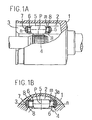
- a tripod member 4 has three radially protruding trunnions 11, which carry rollers 13 respectively rotatably fitted through rolling elements 12 over cylindrical outer circumferential surfaces of the trunnions 11, is inserted into an outer member 1 having three cylindrical track grooves 2 formed in an inner surface of and extending axially of the outer member 1.
- Each of the rollers 13 is accommodated in the corresponding track groove 2 so that it may travel along the track groove 2 rotating about an axis of the trunnion with an outer circumferential surface in engagement with one of a pair of side walls of the track groove 2, which walls provide roller guide surfaces 3 opposing circumferentially of the outer member 1.
- each of the rollers 13 and one of the roller guide surfaces 3 of the corresponding track groove 2 come into an obliquely intersecting relation to each other as shown in Fig. 10.
- the roller 13 tends to roll and move in a direction indicated by an arrow a in Fig. 9, because the track groove 2 has a cylindrical configuration parallel to the axial direction of the outer member 1, the roller 13 results in moving while undergoing restriction. Accordingly, the roller 13 slips in relation to the roller guide surface 3 so that the evolution of heat occurs and an axial induced thrust takes place.
- This induced thrust causes the occurrence of vibration of a vehicle body and the generation of noises, and hence the more reduced induced thrust is desirable.
- a two-story construction type comprising a combination of an inner ring and an outer ring as a roller
- an inner ring 18 is rotatably fitted through rolling elements 12 over a cylindrical outer circumferential surface of a trunnion 11 of a tripod member 4 while an outer ring 19 is rotatably fitted over an outer circumferential surface of the inner ring 18, thus producing a two-story construction.
- the inner ring 18 has a true-spherical outer circumferential surface 18a with its center on the axis of the trunnion 11, and a cylindrical inner circumferential surface 19a of the outer ring 19 is rotatably fitted over the true-spherical outer circumferential surface 18a.
- the outer ring 19 is accommodated in the track groove 2 of the outer member 1 so that it may travel in the axial direction of the outer member 1 rolling on a roller guide surface 3 of the track groove 2.
- the inner ring 18 is inclined with respect to the outer ring 19, where the inner ring 18 relatively shifts downwardly in Fig.
- the outer ring 19 is guided along roller guide surfaces 3 of the outer member 1 while maintaining a position parallel to the axial direction of the outer member 1, with the result that it correctly rolls on the roller guide surface 3 with less sliding friction.
- the sliding resistance is reducible to suppress the generation of the induced thrust.
- the roller 24 is accommodated in a track groove 2 of an outer member 1 so that it may travel along the track groove 2. Also in the joint as shown in Fig. 13, when the transmission of torque is made in a state where the outer member 1 and the tripod member 4 make a working angle ⁇ as shown in Fig. 14, the cylindrical inner circumferential surface of the roller 24 gets into inclination to the outer circumferential surface 22 of the trunnion 21 and the roller 24 more or less pivots relative to the trunnion 21, which allows the roller 24 to be guided by roller guide surfaces on both sides of the track groove 2 of the outer member 1 to be somewhat in parallel to the axis of the outer member 1. Thus, the roller 24 rolls on the roller guide surface 3 in the axial direction of the outer member 1 so that the sliding resistance of the roller 24 is reducible to lessen the induced thrust.
- a desirable radial gap g (not shown in the illustration) be defined between the outer circumferential surface 22 of the trunnion 21 and the rolling elements 23. More specifically, as shown in Fig. 15A the radius of curvature (approximate value) in the central portion of the gentle curvature outer circumferential surface 22 of the trunnion 21 is taken to be R and its outer diameter is taken as 2r.
- a tripod type constant universal joint comprises rollers rotatably carried, through cylindrical rolling elements, on three trunnions of a tripod member are accommodated, respectively, in thrack grooves formed in an inner ciucumferential surface of an outer member in an axial direction, so that the rollers are movalbe axially of the outer member along roller guide surfaces at opposite sides of each of the track grooves and extending axially of the outer member, wherein an inner circumberential surface of the roller is cylindrical, and wherein a generatrix of an outer circumferential surface of the trunnion is defined with a combination of circular arcs at opposite ends of the trunnion and a curve between the circular arcs, the circular arcs having one and same center of curvature on the axis of the trunnion to constitute a part of a true circle, the curve having a radius of curvature larger than that of the circular arcs to be smoothly joined to the cirucular
- the term curve may also be a substantially straight line which corresponds to the curve whose radius of curvature is enlarged up to inifinity.
- the axial central portion of the generatrix on the outer circumferential surface of the trunnion is defined to be literally the curve, it is also possible to employ not only a circular arc having a single center of curvature and a single radius of curvature but a combination of a plurality of circular arcs different in center of curvature and radius of curvature from each other.
- those which are closer to the circular arcs at both ends of the trunnion and constituting a part of a true circle may have a center of curvature at a position nearer to that of the circular arcs constituting a part of a true circle so that a smoothly continuous generatrix is attainable on the outer circumferential surface of the trunnion.
- the intermediate portion of the outer circumferential surface of the trunnion assumes a curved surface with a gentle curvature than the true spherical surface, and in the case that the radius of curvature of the intermediate portion is infinite, it assumes a substantially cylindrical surface parallel to the axial direction of the trunnion just as mentioned previously.
- the rolling element is always brought into contact with the intermediate curved surface including such a substantially cylindrical surface, its maximum surface (bearing) pressure is reducible than the maximum surface pressure taking place at the contact of a true spherical surface, and accordingly the local carrying capacity increases so that the durability improves.
- the outer circumferntial surface of the trunnion is true spherical with the center of curvature on the axis of the trunnion.
- the roller fitted over the true spherical outer circumferential surface of the trunnion is one in number to define the so-called one-story construction, and the true spherical outer circumferential surface of the trunnion is fitted through a plurality of rolling elements in the cylindrical inner circumferential surface of the roller.
- the radial gap is not required to be defined between the rolling elements and the outer circumferential surface. That is, the trunnion can freely pivot or tilt with respect to the roller, and irrespective of the magnitude of the tilting angle the relation in dimension between the outer circumferential surface of the trunnion and the rolling elements is always kept constant.
- the true spherical outer circumferentail surface of the trunnion of the tripod member relatively rotates about its center of curvature and moves with respect to the cylindrical inner circumferential surface of the roller fitted in the track groove of the outer member to cause the roller to relatively shift in the axial direction of the track groove.
- the generation of the induced thrust is suppressible as well as the prior joint with the two-story construction, thus providing a tripod type constanct velocity univiersal joint with high quality and performance which can develop less occurrence of temperature rise, vibration, and noise.
- angular contact may be established between the roller guide surface of the track groove of the outer member and the outer circumferential surface of the roller.
- a shoulder may be formed along the roller guide surface for engagement with an end surface of the roller to thereby limit the rolling direction of the roller to a direction parallel to the track groove.
- the angular contact between the roller guide surface of the track groove of the outer member and the outer circumferential surface of the roller or the shoulder of the roller guide surface stably makes a limitation of the movement of the roller to travel in the axial direction of the outer member when the joint operates in a state with making a working angle, with the result that the generation of the induced thrust is more surely and stably suppressible.
- the strength of the tripod type constant velocity universal joint greatly depends upon the strength of the roller and the strength of the rolling elements, if (geometrical moment of inertia of the roller/PCD 4 ) is set to exceed 0.0281 ⁇ 10 -3 but be below 1.39 ⁇ 10 -3 , and (the diameter of the rolling elements/PCD) is set to exceed 0.0417 but be below 0.378, it is possible to sufficiently satisfy the strength required for the joint for use in a drive system of a motor vehicle. Accordingly, in this case, it is possible to obtain proper dimensions which meet the strength being required and, therefore, to provide a tripod type constant velocity universal joint which can sufficiently satisfying the strength required in using it for a drive system of a motor vehicle.
- the transvese cross section of the trunnion is usually a true circle, whereas it may also be an ellipse with its minor axis pointing the load side.
- the difference between its minor axis and its major axis is approximately several tens to 100 ⁇ and in all the cross-sections perpendicular to the axis of the trunnion the ellipticity is the same.
- the configuration of the outer circumferential surface in the longitudinal section of the trunnion can also comprise a combination of circular arcs at opposite ends of the trunnion with a center of curvature on the axis of the trunnion and a curve between the circular arcs smoothly connected to the circular arcs and having a radius of curvature larger than that of the circular arcs. It is also possible that this curve is made up of a combination of a plurality of circular arcs different in center of curvature and radius of curvature from each other or is made as a substantially straight line corresponding to an arc having an infinite radius of curvature.
- the axial central portion of the trunnion coming into contact with the rolling elements at the maximum surface pressure is formed with a gentle curved surface having a radius of curvature larger than that of a true spherical surface having a center of curvature on the axis of the trunnion, and hence the surface pressure on the rolling element is reducible.
- a tripod type constant velocity universal joint comprises a tripod member having three radially protruding trunnions each of which rotatably carries a roller fitted over an outer circumferential surface of the trunnion with a plurality of cylindrical rolling elements therebetween, and an outer member having three track grooves formed in an inner circumferential surface thereof for receiving the trunnions, respectively, so that each of the rollers may travel axially of the outer member rolling on a roller guide surface of the track groove.
- a stopper may be provided on an inner circumferential surface of the roller to prevent the plurality of cylindrical rolling elements from falling out in their axial direction.
- the stopper may be in the form of an annular step inwardly protruding from the inner circumferential surface of the roller, or alternatively, the stopper may be in the form of a washer attached to an annular groove formed in the inner circumferential surface of the roller, simplifying the roller in structure. Since the stopper is provided on the roller inner circumferential surface, it becomes unnecessary that the parts or structure for preventing the rolling elements from falling out be provided on the trunnion of the tripod member, and hence the number of parts for the tripod member and the number of steps for the assembling decrease and, in addition, the following assembling methods may be adopted for the tripod member.
- a stopper is provided on an inner circumferential surface of a roller of a tripod member to prevent a plurality of successive cylindrical rolling elements from falling out in their axial direction, and the roller, together with the rolling elements, is fitted over a trunnion in a state where the plurality of rolling elements are temporarily attached with a grease on the roller inner circumferential surface along the stopper.
- a stopper is provided on an inner circumferential surface of a roller of a tripod member to pvevent a plurality of cylindrical rolling elements from coming out in their axial direction, and the plurality of rolling elements but one are successively or serially arranged on the roller inner circumferential surface along the stopper and the remaining one rolling element is forced into a gap left between the two of the series of rolling elements positioned at both the ends thereof, and further the roller, together with the rolling elements, is fitted over the trunnion in a state where a given number of rolling elements are temporarily held on the roller inner circumferential surface.
- the rolling elements are temporarily adhered with a grease onto the roller inner circumferential surface, and the stopper of the roller prevents the rolling elements from coming out when the roller, together with the rolling elements, is fitted over the trunnion of the tripod member.
- the latter manufacturing method for serially arranging the rolling elements on the roller inner circumferential surface is the so-called Keystone method using no adhesive, and also in this instance the stopper of the roller prevents the rolling elements from falling out when the roller, together with the rolling elements, is filled over the trunnion of the tripod member.
- the roller and the rolling elements are integrally and simultaneously combined with the trunnion, the number of steps for assembling the tripod member can decrease and assembling work efficiency can improve, thus providing a tripod type constant velocity universal joint which is excellent in quality production and low in cost.
- a tripod type constant velocity universal joint comprises an outer member 1 adapted to connect with one of two rotary axes being coupled together by the joint and a tripod member 4 adapted to connect with the other of the two axes.
- the outer member 1 is gererally cup-shaped and has three circumferentially equispaced, axially extending track grooves 2 formed in an inner circumferential surface.
- the tripod member 4 has three circumferentially equispaced, radially protruding trunnions 5, each of which rotatably carries a roller 7 with rolling elements therebetween.
- the rollers 7 are respectively accommodated in the track grooves 2 of the outer member.
- the rollers 7 have cylindrical inner circumferential surface n which is filled through the plurality of rolling elements 6 over an outer circumferential surface m of the trunnion, which surface m in turn is a part of a true sphere with its center p of curvature on the axis of the trunnion 5.
- the rolling elements 6 have a cylindrical rolling surface whose diameter is relatively large and whose length is not very long as compared with its diameter. In this respect, the rolling elements 6 are in contrast to needle rollers. Washers 8 are attached to both opening end portions of the inner circumferential surface n of the roller to prevent the rolling elements 6 from falling out.
- the gereratrix of an outer circumferential surface of the roller 7 is a circular arc having its center of curvature at point p spaced apart radially outwardly from the center P R of the roller.
- the track grooves 2 accommodating the rollers 7 extend axially of the outer member 1.
- a pair of side walls of each of the track grooves 2 oppose each other circumferentially of the outer member 1 and provide roller guide surfaces 3 for engagement with the outer circumferential surface of the roller 7.
- each of the roller guide surfaces 3 is a cylindrical surface with its axis passing point p spaced apart radially outwardly form the center P R of the roller 7.
- the roller 7 Since the generatrix of the outer circumferential surface of the roller 7 is a circular arc having its center of curvature at a point spaced apart from the center of the roller 7, the roller 7 can hardly incline as viewed in the longitudinal section (Fig. 1A) but runs parallel with the direction in which the roller guide surface 3 extends, i.e. the axial direcion of the outer member 1, ensuring that the roller 7 smoothly rolls on the roller guide surface 3.
- This is also applicable where the axes being coupled together by the joint are at an angle or the working angle. As shown in Fig. 3, when the joint makes a working angle ⁇ , the tripod member 4 is inclined by an angle ⁇ with respect to the outer member 1.
- the true-spherical outer circumferential surface m of the trunnion 5 relatively rolls and moves within the cylindrical inner circumferential surface n of the roller 7 (through the rolling elements 6), while the roller 7 rolls and moves along the roller guide surfaces 3 within the track groove 2 while taking a position parallel to the axis of the outer member 1, and in this situation the sliding resistances at the respective portions come down to suppress the occurrence of the induced thrust.
- the mechanism to reduce the induced thrust when operating in a state with making a working angle is basically the same as that of the two-story roller construction as shown in Figs. 11 and 12, and a description thereof will be taken hereinbelow with reference to Fig. 4.
- the axis of the trunnion 5 is inclined by an angle ⁇ , whereas the center P of the true-spherical outer circumferential surface m relatively moves downwardly from the center line B of the roller guide surface 3 up to a position P' in Fig. 4.
- the true-spherical outer circumferential surface m of the trunnion 5 tends to move on the cylindrical inner circumferential surface n of the roller 7 while rotating about the center P, besides this movement is smooth due to the interposition of the rolling elements 6 (omitted in Fig. 4 for clarity; see Fig. 3) therebetween.
- the roller 7 rolls and moves along the roller guide surface 3 to shift in the direction of the axis X of the outer member 1 parallel to the center line B of the roller guide surface 3 as indicated by an arrow pointing to the right in the illustration.
- the relative movement between the trunnion 5 and the roller 7 and the relative movement between the roller 7 and the roller guide surface 3 are achievable with extremely low resistances, with the result that the occurrence of the induced thrust is suppressible.
- a shoulder 3a may advantageously be formed so as to extend axially of the outer member 1 along an upper edge of the roller guide surface 3.
- the roller 7 always comes into contact at an end surface thereof with the shoulder 3a, and therefore, maintains its position in parallel to the axis of the outer member 1.
- the roller 7 is guided axially of the outer member 1 as it travels along the roller guide surface 3, resulting in the position of the roller 7 being effectively stabilized even when the joint operates in a state with making a working angle.
- the roller guide surface 3 may be of any shape including the cylindrical shape as described previously.
- the angular contact fashion is adopted in which the outer circumferential surface l of the roller 7 and the roller guide surface 3 come in contact at two points Q and Q spaced apart axially of the roller 7.
- this arrangement allows the roller 7 to run paralle with the direction in which the roller guide surface 3 extends, that is, the axial direction of the outer member 1.
- the gap or space confined by the roller guide surface 3 and the roller outer circumferential surface between the two contact points Q and Q effectively serves as a grease pocket.
- the gereratrix configuration of the roller guide surface 3 can assume a Gothic arch, an ellipse, a parabola, hyperbola or the like.
- the gereratrix configuration of the outer circumferential surface of the roller 7 can be defined, for example, with a circular arc having a center of curvature on the axis of the roller 7, a circular arc having a center of curvature at a point radially spaced apart from the axis of the roller, either towards or away from the outer circumferential surface of the roller, or a combination of circular arcs having centers of curvature at points spaced apart from each other in the axial direction of the roller 7.
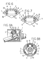
- Fig. 6 shows a modification in which a pair of opposing roller guide surfaces 3 constituting side walls of the track groove 2 are parallel flat surfaces.
- shoulders 3a and 3b are formed along upper and lower edges of each roller guide surface.
- a fringing portion of the roller 7 is fitted between the pair of shoulders 3a, 3b, and the cylindrical outer circumferential surface of the roller 7 is engaged with the flat roller guide surfaces 3.
- both the end surfaces of the roller 7 engage with the shoulders 3a, 3b, with the result that the position of the roller 7 in the axial direction of the outer member 1 is stably controllable.
- annular flanges 9 are integrally formed at both ends of the cylindrical inner surface of the roller 7 to support the rolling elements 6. With this construction, it is possible to omit the washers 8 for preventing the rolling elements from coming out, which can decrease the number of parts for the roller section.
- the strength taken as a criterion or reference depends upon, for example, the strength of a shaft to be coupled to this constant velocity universal joint. Accordingly, for a tripod type constant velocity universal joint (see Fig. 16) of the type that the trunnion 5 has a true-spherical outer circumferential surface as previously described, a strength test was made from the viewpoint of determining dimensional requirements to satisfy a strength condition. As a result of the test, it was found that two points: the strength of the roller 7 and the strength of the rolling elements 6, exerted influence.
- the geometrical moment of inertia of the roller 7 greatly has influence on the strength of the roller 7, and the strength of the rolling elements 6 relies upon the diameter of the rolling elements.
- the respective dimensions were divided by pitch diameter (herein after PCD) for dimensionless, thus attaining the following conditional equations (2) and (3).
- a (the geometrical moment of inertia of area of the roller / PCD 4 )
- b the diameter of the rolling elements / PCD
- Fig. 17 is an illustration obtained by plotting test data on a plurality of tested joints different in values a and b, where the horizontal scale represents the value a while the vertical scale denotes the value b.
- Each of the test data includes a mark indicative of an evaluation and values a, b and c.
- the white circle ⁇ represents “strength OK", that is, satisfying the condition of c > 0.93
- the white lozenge ⁇ designates “rolling element no good (NG)", that is, signifying that the rolling element is in poor condition
- the black lozenge ⁇ denotes that the roller is in poor condition
- the black circle ⁇ depicts "roller and rolling element NG”, that is, meaning that both the roller and rolling element are in poor condition
- the cross X stands for “obviously NG”, that is, signifying that the shortage of the strength is obvious without making the test.
- the range of the value of the conditional equation a (equation 2) relating to the roller 7 is expressed with the mark A, and its lower limit is 0.0281 ⁇ 10 -3 .
- the roller outer diameter is enlarged to a maximum and the trunnion journal diameter and the rolling element diameter are set to a minimum so that the roller wall thickness comes to a maximum, according to the calculation the upper limit comes to 1.39 ⁇ 10 -3 . From this, the range of a becomes 0.0281 ⁇ 10 -3 ⁇ a ⁇ 1.39 ⁇ 10 -3 .
- the range of the value of the conditional equation b (equation 3) concerned with the rolling elements is expressed by the mark B, and its lower limit is 0.0417. Further, on the conditions that the outer member outer diameter is fixed, the roller outer diameter is enhanced to a maximum, the trunnion diameter and the roller wall thickness are set to a minimum and the rolling element diameter is maximized, according to the calculation the upper limit amounts to 0.378. From this, the range of b is 0.0417 ⁇ b ⁇ 0.378.
- the roller and the rolling elements of the constant velocity universal joint for a drive system of a motor vehicle i.e., the whole joint, can have a sufficient strength.
- a large number of independent microscopic dents each having a recess shape were made in the surfaces of the rolling elements 6.
- a special barrel polishing can be employed as the surface processing therefor, thus obtaining a desirable finished surface.
- the surface roughness of the rolling elements is Rmax 0.6 to 2.5 ⁇ m and the parameter SK value of the surface roughness is below -1.6.
- the mean area of the dents is 35 to 180 ⁇ m 2 while the rate of the dents to the entire surface is 10 to 40%.
- the aforesaid parameter SK value denotes the skewness (strain) of the distribution curve showing the surface roughness.
- the parameter SK value becomes 0, and the preferable range of the parameter SK value for providing the shape and distribution of the recesses advantageous to lubricating film formation, although depending on processing conditions, is below -1.6 both in the circumferential direction and in the axial direction.
- Fig. 18 shows the results of the endurance tests made in terms of a tripod type constant velocity universal joint in which the outer circumferential surface of the turnnion is a true spherical surface, using the rolling elements subjected to the above-described surface processing and the conventional rolling elements experiencing a superfinishing processing.
- the test conditions A and B in the same illustration are respectively shown in the following table 1.
- Test Condition Bearing Load Speed of Joint Lubricant A 1438 kgf 200 rpm grease B 902 kgf 500 rpm grease
- the conventional rolling elements come into poor condition at the time of working for 96 hours.
- the rolling elements according to this invention are still in good condition even after the operating time exceeds more than 160% as compared with the conventional ones.
- the lifetime of the rolling elements according to this invention lengthens more than 200% as compared with the conventional ones.
- the above-mentioned surface processing for the rolling elements is effective for the formation of the lubricating film on the rolling element surfaces to enhance the lubricity, so that the rotating performance of the roller can improve and the sliding performance between the rolling elements and the roller and between the rolling elements and the trunnion journal can improve to reduce the occurrence of abrasion and peeling of the contact portions to the utmost.
- a moment in a direction of a vector M due to the trunnion 5 acts through the plurality of rolling elements 6 on the roller 7, which makes the position of the roller 7 unstable, whereby difficulty is further encountered in the reduction of the induced thrust.
- the stress easily concentrates on the rolling elements 6 bearing the load irrespective of the magnitude of the working angle, which has influence on the durability of the rolling elements and others.
- an outer circumferential surface of each of three trunnions 5 (only one is shown in the illustrations) of a tripod member 4 is composed of true spherical surfaces m 1 having a center of curvature on the axis of the trunnion 5 and an intermediate curved surface m 2 standing at a central portion in the axial direction of the trunnion 5 having a radius of curvature R 2 larger than the radius of curvature R1 of the true spherical surface m 1 .
- a cylindrical inner circumferential surface n of a roller 7 is rotatably filled through rolling elements 6 over an outer circumferential surface of the trunnion 5.
- the roller 7 is inserted into a track groove 2 of an outer member 1 so as to travel axially of the outer member 1 rolling on an roller guide surface 3 of the track groove 2.
- the generatrix for the outer circumferential surface of the trunnion 5 is defined with a combination of circular arcs (m 1 ) lying at both axial ends of the trunnion 5 and having one and same center of curvature on the axis of the trunnion 5 to constitute a part of a true circle and a circular arc (m 2 ) having a radius of curvature larger than that of the first-mentioned circular arcs (m 1 ).
- the intermediate curved surface m 2 of the trunnion 5 signifies an area where the rolling elements 6 always come into contact at the maximum surface pressure. That is, its width (the dimension in the axial direction) is determined so that the rolling elements 6 principally bearing the load come into contact with the intermediate curved surface m 2 when the tripod member 4 transmits torque at the normal working angle (approximately 2 to 10 deg) with respect to the outer member 1.
- the intermediate curved surface m 2 has a gentler curvature than that of the true spherical surface m 1 , and it is preferable that its radius of curvature R2 is approximately twice to five times the radius of curvature R 1 of the true spherical surface m 1 .
- the maximum outer diameter of this intermediate curved surface m 2 is set to be smaller than the outer diameter of the true spherical surface m 1 .
- a modification shown in Figs. 21A and 21B is characterised in that a cylindrical surface m 3 is formed in an intermediate portion of the true spherical surfaces m 1 of the trunnion 5.
- the generatrix for the outer circumferential surface of the trunnion 5 is made with a combination of circular arcs (m 1 ) having a center of curvature on the axis of the trunnion 5 to constitute a part of a true circle and a straight line (m 3 ).
- the straight line (m 3 ) corresponds to the aforesaid curve (m 2 ) in Fig. 20A with the radius of curvature R 2 made infinite.
- the cylindrical surface m 3 is in parallel to the axis of the trunnion 5 and comes into linear contact with the cylindrical rolling elements 6 and, therefore, the maximum surface pressure is more reducible.
- the combination configuration of the true spherical surfaces m 1 and the cylindrical surface m 3 can more easily be produced as compared with the aforesaid intermediate curved surface m 2 .
- the outer circumferential surface of the trunnion 5 of the tripod member 4 is characterised by being a circular arc m 4 having a center on the axis as viewed in a longitudinal section (Fig. 22A) but being an ellipse m 5 whose minor axis points the load side as viewed in a cross section (Fig. 22B).
- a dashed line represents the case of a true circle.
- the elliptical degree of the ellipse m 5 is approximately several tens to 100 ⁇ in the difference between the minor axis (load side) and the major axis (non-loaded side), and all the cross sections perpendicular to the axis of the trunnion 5 assumes the same difference.
- the transverse cross-sectional configuration of the trunnion 5 is made to be the ellipse m 5 whose minor axis points the load side, as compared with the joint as shown in Figs. 1A and 1B the stress concentration to the rolling elements 6 which come into contact with the load side outer circumferential surface of the trunnion 5 can be lessened, whereby the maximum surface pressure is reducible and the durability is improvable.
- the rolling elements interposed between the trunnion and the roller are mainly brought into contact with the surface portion of the trunnion having the gentler curvature, which contributes to the reduction of the maximum surface pressure of the rolling elements and further to the suppression of the induced thrust, thus providing a tripod type constant velocity universal joint which is capable of making less vibration and creating a high durability.
- the surface pressure reduction is further possible.
- the outer circumferential surface of the trunnion is made with a combination of a true spherical surface and a cylindrical surface, the processing is easy to cut down the manufacturing cost of the constant velocity universal joint.
- the transverse cross-sectional configuration of the trunnion of the tripod member assumes an ellipse whose minor axis points the load side (Figs. 22A and 22B)
- the stress concentration on the rolling elements contacting with the trunnion can be mitigated, thereby providing a tripod type constant velocity universal joint which is excellent in the reduction of the induced thrust and the durability.
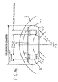
- Figs. 23A and 23B show a modification in which the outer circumferential surface of the trunnion 5 is made to be the so-called torus surface m 6 .
- torus surface m 6 a circular arc having a center at a point spaced radially outwardly from the axis of the trunnion 5 and having a radius R 3 is used as the generatrix and the axial central portion of the trunnion 5 assumes the largest outer diameter (2R 1 ).
- the number of rolling elements 6 bearing the load decreases in accordance with the difference in radius [R 1 - R 3 ], and accordingly the vector M direction moment receiving from the trunnion 5 and working on the roller 7 decreases to stabilize the position of the roller 7 as compared with the case of the true spherical surface, with the result that the induced thrust is reducible.
- the difference in radius [R 1 - R 3 ] is set to approximately 1 to 2 mm so as not to increase the surface pressure.
- Fig. 24 shows the results of the measurement of the induced thrust in the case of the embodiment shown in Figs. 1A and 1B and the modification shown in Figs. 23A and 23B.
- the outer circumferential surface of the trunnion is a true spherical surface having the radius of curvature of 19.095 mm.
- the induced thrust takes the relation of the embodiment ⁇ the modification until the working angle taken when in operation rises up to approximately 6 deg, while in the range of the working angle exceeding 6 deg the induced thrust takes, on the contrary, the relation of the embodiment > the modification.
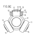
- the outer circumferential surface of the trunnion 11 of the tripod member 4 is, for example, a cylindrical surface as shown in Fig. 8C, and an inner washer 14 is filled over the proximal portion of this cylindrical surface and an outer washer 15 and a clip 16 are fitted over the tip portion thereof, and further a plurality of rolling elements are placed between both the washers 14, 15.
- the plurality of rolling elements 6 are serially arranged along the outer circumference of the trunnion 5 without making gaps therebetween.
- the outer washer 15 is placed into contact with an end surface of the rolling elements 12 to limit the axial position of the rolling elements 12 and further to prevent them from falling out.
- the clip 16 is filled in a groove 17 made in the outer circumference of the trunnion 11 to fix the outer washer 15 against the trunnion 11.
- a plurality of rolling elements 12 are successively arranged on the outer circumference of the trunnion 11 and then a roller 13 is fitted over them, or alternatively, the roller 13 is fitted over the trunnion 11 and the plurality of rolling elements are inserted into an annular space formed between the trunnion 11 and the roller 13.
- both the cases require a large number of steps for assembling and are hard to assemble, thus deteriorating the assembling working efficiency of the tripod type constant velocity universal joint.
- the outer washer 15 for preventing the rolling elements mounted on the trunnion 11 from falling out is required to have a special shape as shown in the illustration for also preventing the roller 13 from coming out, and the clip 16 for setting the outer washer 15 on the trunnion 11 is additionally necessary, with the result that the number of parts for the tripod member 4 and the number of assembling steps become many so that difficulty is encountered to lower the manufacturing cost thereof.
- a tripod type constant velocity universal joint according to an embodiment of this invention which can eliminate the above-mentioned problems and which is capable of improving the assembling working efficiency and lowering the manufacturing cost.
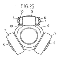
- a stopper 10 for preventing a plurality of rolling elements 6 from falling out is formed on an inner circumferential surface of a roller 7 fitted through the rolling elements 6 over the outer circumference of each of trunnions 5.
- the outer circumferential surface of the trunnion 5 is a cylindrical surface, and a plurality of cylindrical rolling elements 6 such as rollers and needle rollers are serially disposed on this cylindrical outer circumferential surface without defining gaps therebetween, and the cylindrical inner circumferential surface of the roller 7 is located around these rolling elements 6.
- the stoppers 10 are in the form of a pair of annular step portions 9 formed at both ends of the roller 7 to protrude from the cylindrical inner circumferential surface of the roller 7.
- a groove for accommodating the rolling elements 6 for rolling motion is formed in a central section of the cylindrical inner circumferential surface of the roller 7 so that the axial end portions thereof define the inwardly protruding annular steps 9.
- the stoppers 10 are in the form of a pair of washers 8 filled in grooves 8a formed in both axial end portions of the cylindrical inner circumferential surface of the roller 7. The protruding amount of the washer 8 from the roller cylindrical inner circumferential surface corresponds to the step (difference in level) of the annular step 9 in Fig. 26A.
- the roller 7, together with the rolling elements 6, is fitted over the trunnion 5 in a state where all the rolling elements 6 are serially arranged along and temporarily adhered to the cylindrical inner circumferential surface of the roller 7 with a grease 10a.
- the grease 10a is of the well-known type for lubricating the rolling elements, and this grease 10a is applied in advance to the cylindrical inner circumferential surface of the roller 7 to make a desired thickness thereon and the rolling elements 6 are pressed against the applied grease 10a so that the plurality of rolling elements 6 are subjected to the temporary adhesion.
- roller 7, together with the rolling elements 6, is filled over the cylindrical outer circumferential surface of the trunnion 5, with the result that the stoppers 10 (9) of the roller 7 prevent the rolling elements 6 from coming out and the attachment of the roller 7 and the rolling elements 6 to the trunnion 5 can surely and smoothly be done.
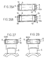
- Fig. 28 shows a method in which the roller 7, together with a plurality of rolling elements 6, is mounted over the trunnion 5 in a state that the rolling elements 6 are temporarily serially attached to the cylindrical inner circumferential surface of the roller 7 according to the so-called Keystone method.
- Figs. 29A and 29B all the rolling elements 6 but one are serially arranged on the cylindrical inner circumferential surface of the roller 7, and the last one 6 is forced into a gap g defined between the two of this series of rolling elements 6 positioned at both the ends thereof.
- the relation between the diameter d 1 of the rolling elements 6 and the minimum separation d 2 of the gap g is set to be d 1 > d 2 , the difference [d 1 - d 2 ] being an interference of several ⁇ to several tens ⁇ .
- the stoppers 10 (9) of the roller 7 prevent the falling-out of the rolling elements 6 and the mounting of the roller 7 and the rolling elements 6 on the trunnion 5 is surely and smoothly achievable.
- the plurality of rolling elements 6 attached in advance to the roller 7 according to the Keystone method can smoothly rotate between the roller 7 and the trunnion 5 with no problem as long as having the above-mentioned interference.
- the work for setting the unit, in which the rolling elements 6 are combined with the roller 7, to the trunnion 5 to assemble the tripod member 4 is technically easier as compared with the conventional assembling work, and its number of working steps for assembling decreases, thus further improving the assembling working efficiency.
- the stoppers 10 (9) are integrally formed on the roller cylindrical inner circumferential surface, since it is possible to omit the washers or clips for preventing the rolling elements fitted over the trunnion from falling out, the number of parts for the tripod member 4 and the number of steps for assembling are reducible, thus easily culling down the manufacturing cost.
- the stoppers 10 are constructed using the washers 8, it is possible to assemble the tripod member through the use of the adhering method based on the grease in Fig. 27 and through the use of the Keystone method in Fig. 28.
- the washers 8 can be constructed with cheap flat washers with a simple configuration which merely protrude from the cylindrical inner circumferential surface of the roller 7, so that it is possible to cut down the manufacturing cost of the tripod member.
- the outer circumferential surface of the trunnion 5 of the tripod member 4 shown in Fig. 30 is a true spherical surface having its center P 1 on the axis of the trunnion 5 and having a radius R 1 , and the rolling members 6 are brought into point contact with this true spherical surface to be slidable, and further the roller 7 is pivotably mounted relative to the trunnion 5.
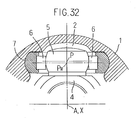
- the outer circumferential surface of the trunnion 5 of the tripod member 4 shown in Fig. 31 has a circular generatrix whose center P 2 is separated from the axis of the trunnion 5 and whose radius is R 2 .
- the rolling elements 6 are placed into point contact with this outer circumferential surface to be slidable, and the roller 7 is pivotably mounted relatively to the trunnion 5.
- the center of the trunnion 5 and the center of the roller 7 are shown as coexisting with each other as at point P even when the two axes being coupled together by the joint are not at an angle, though, they may be offset axially of the trunnion 5.
- the center P of the trunnion 5 shifts towards the axis X of the outer member 4, i.e., from P to P', as previously described in conjunction with Fig. 4, and therfore, the centers of the trunnion 5 and roller 7 are offset axially of the trunnion 7.
- the center P R of the roller may be spaced apart from the center P of the trunnion 5 by a predetermdined amount towards the axis X of the outer member 4; this ensures that when the axes being coupled by the joint are at an angle, the center P of the trunnion 5 shifts towards the axis X of the outer member 1 to coincide with or approach the center of the roller 7.
- This arrangement takes account of the movements encountered by the components of the joint in transmitting torque between the two rotary axes which are at an angle, and its significance will be apparent in view of the fact that in the joint of this kind the two rotary axes being coupled are usually at an angle.
Abstract
Description
- The present invention relates to a tripod type constant velocity universal joint which is applicable to front-wheel drive vehicles and others.
- In front-wheel drive vehicles, as a constant velocity universal joint for transmitting torque from a drive shaft to front wheels at a constant velocity, there has been taken a joint of a tripod type as shown in Figs. 8A and 8B. In this tripod type, a
tripod member 4 has three radially protrudingtrunnions 11, which carryrollers 13 respectively rotatably fitted throughrolling elements 12 over cylindrical outer circumferential surfaces of thetrunnions 11, is inserted into anouter member 1 having threecylindrical track grooves 2 formed in an inner surface of and extending axially of theouter member 1. Each of therollers 13 is accommodated in thecorresponding track groove 2 so that it may travel along thetrack groove 2 rotating about an axis of the trunnion with an outer circumferential surface in engagement with one of a pair of side walls of thetrack groove 2, which walls provideroller guide surfaces 3 opposing circumferentially of theouter member 1. - In cases where as shown in Fig. 9 the transmission of torque is made in a state that the
outer member 1 and thetripod member 4 make a working or operating angle with respect to each other, each of therollers 13 and one of theroller guide surfaces 3 of thecorresponding track groove 2 come into an obliquely intersecting relation to each other as shown in Fig. 10. In this case, although theroller 13 tends to roll and move in a direction indicated by an arrow a in Fig. 9, because thetrack groove 2 has a cylindrical configuration parallel to the axial direction of theouter member 1, theroller 13 results in moving while undergoing restriction. Accordingly, theroller 13 slips in relation to theroller guide surface 3 so that the evolution of heat occurs and an axial induced thrust takes place. This induced thrust causes the occurrence of vibration of a vehicle body and the generation of noises, and hence the more reduced induced thrust is desirable. - For a tripod type constant velocity universal joint which is capable of reducing the aforesaid induced thrust to a certain extent, there has been known a two-story construction type comprising a combination of an inner ring and an outer ring as a roller (U.S. Patent No. 4,786,270). For instance, as shown in Figs. 11 and 12, in this type of joint, an inner ring 18 is rotatably fitted through
rolling elements 12 over a cylindrical outer circumferential surface of atrunnion 11 of atripod member 4 while an outer ring 19 is rotatably fitted over an outer circumferential surface of the inner ring 18, thus producing a two-story construction. The inner ring 18 has a true-spherical outer circumferential surface 18a with its center on the axis of thetrunnion 11, and a cylindrical inner circumferential surface 19a of the outer ring 19 is rotatably fitted over the true-spherical outer circumferential surface 18a. The outer ring 19 is accommodated in thetrack groove 2 of theouter member 1 so that it may travel in the axial direction of theouter member 1 rolling on aroller guide surface 3 of thetrack groove 2. In the case that the transmission of torque is made in a state where theouter member 1 and thetripod member 4 make a working angle as shown in Fig. 12, the inner ring 18 is inclined with respect to the outer ring 19, where the inner ring 18 relatively shifts downwardly in Fig. 12 in relation to the cylindrical inner circumferential surface 19a of the outer ring 19. Owing to the occurrence of the relative movement between the inner and outer rings 18, 19, the outer ring 19 is guided alongroller guide surfaces 3 of theouter member 1 while maintaining a position parallel to the axial direction of theouter member 1, with the result that it correctly rolls on theroller guide surface 3 with less sliding friction. Thus, the sliding resistance is reducible to suppress the generation of the induced thrust. - In addition, as another tripod type constant velocity universal joint which can reduce, though to a certain extent only, the aforesaid induced thrust, there has been known a type in which a roller is pivotably supported with an outer circumferential surface of a trunnion of a tripod member (U.S. Patent No. 4,379,706). As shown in Figs. 13 and 14, this joint features that an outer
circumferential surface 22 of atrunnion 21 of atripod member 4 assumes a curved surface with a gentle curvature. In this case, a cylindrical inner circumferential surface of aroller 24 is pivotably fitted throughrolling elements 23 over the outercircumferential surface 22 of thetrunnion 21 having the gentle curvature. Theroller 24 is accommodated in atrack groove 2 of anouter member 1 so that it may travel along thetrack groove 2. Also in the joint as shown in Fig. 13, when the transmission of torque is made in a state where theouter member 1 and thetripod member 4 make a working angle as shown in Fig. 14, the cylindrical inner circumferential surface of theroller 24 gets into inclination to the outercircumferential surface 22 of thetrunnion 21 and theroller 24 more or less pivots relative to thetrunnion 21, which allows theroller 24 to be guided by roller guide surfaces on both sides of thetrack groove 2 of theouter member 1 to be somewhat in parallel to the axis of theouter member 1. Thus, theroller 24 rolls on theroller guide surface 3 in the axial direction of theouter member 1 so that the sliding resistance of theroller 24 is reducible to lessen the induced thrust. - In the joint with a two-story roller construction as shown in Fig. 11, there has been known the fact that it is possible to stably produce the induced thrust reduction effect when operating in a state with making the working angle. However, this is disadvantageous in that, because the roller is constructed with a combination of an inner ring and an outer ring, in addition to the number of parts for the roller section the number of assembling steps increases to cause the rise of its manufacturing cost. In the case of the Fig. 13 joint, the roller has a simple (one-story) construction as well as the basic structure shown in Figs. 8A and 8B, so that the rise of the manufacturing cost is avoidable. On the other hand, in this joint, even if the
outer member 1 and thetripod member 4 make the working angle as shown in Fig. 14, it is necessary that, to permit theroller 24 to always maintain the position parallel to thetrack groove 2, a desirable radial gap g (not shown in the illustration) be defined between the outercircumferential surface 22 of thetrunnion 21 and therolling elements 23. More specifically, as shown in Fig. 15A the radius of curvature (approximate value) in the central portion of the gentle curvature outercircumferential surface 22 of thetrunnion 21 is taken to be R and its outer diameter is taken as 2r. When thetrunnion 21 is inclined by a working angle as shown in Fig. 15B, the outercircumferential surface 22 comes into contact with therolling elements 23 at the portions C, C' where it meets with a chain line b and a chain line c. Since these two portions C, C' stand on the radiustrunnion 21 to smoothly tilt with respect to theroller 24, it is required that as the angle allowing for the tilting therebetween the radial gap g be set to a given value to satisfyroller 24 to take a position parallel to thetrack groove 2 at all the required values of working angle unless the looseness is allowed to increase. - It is therefore a principal object of the present invention to provide a tripod type constant velocity universal joint with a high performance which is capable of surely reducing the looseness and the induced thrust when operating in a state with making a working angle.
- In accordance with one aspect of the present invention, a tripod type constant universal joint comprises rollers rotatably carried, through cylindrical rolling elements, on three trunnions of a tripod member are accommodated, respectively, in thrack grooves formed in an inner ciucumferential surface of an outer member in an axial direction, so that the rollers are movalbe axially of the outer member along roller guide surfaces at opposite sides of each of the track grooves and extending axially of the outer member, wherein an inner circumberential surface of the roller is cylindrical, and wherein a generatrix of an outer circumferential surface of the trunnion is defined with a combination of circular arcs at opposite ends of the trunnion and a curve between the circular arcs, the circular arcs having one and same center of curvature on the axis of the trunnion to constitute a part of a true circle, the curve having a radius of curvature larger than that of the circular arcs to be smoothly joined to the cirucular arcs.
- In this case, the term curve may also be a substantially straight line which corresponds to the curve whose radius of curvature is enlarged up to inifinity. Further, in cases where the axial central portion of the generatrix on the outer circumferential surface of the trunnion is defined to be literally the curve, it is also possible to employ not only a circular arc having a single center of curvature and a single radius of curvature but a combination of a plurality of circular arcs different in center of curvature and radius of curvature from each other. In the case of employing the combination of a plurality of circular arcs for the axially central portion, those which are closer to the circular arcs at both ends of the trunnion and constituting a part of a true circle may have a center of curvature at a position nearer to that of the circular arcs constituting a part of a true circle so that a smoothly continuous generatrix is attainable on the outer circumferential surface of the trunnion.
- In this instance, the intermediate portion of the outer circumferential surface of the trunnion assumes a curved surface with a gentle curvature than the true spherical surface, and in the case that the radius of curvature of the intermediate portion is infinite, it assumes a substantially cylindrical surface parallel to the axial direction of the trunnion just as mentioned previously. When the rolling element is always brought into contact with the intermediate curved surface including such a substantially cylindrical surface, its maximum surface (bearing) pressure is reducible than the maximum surface pressure taking place at the contact of a true spherical surface, and accordingly the local carrying capacity increases so that the durability improves.
- When the generatrix of the outer circumferential surface of the trunnion is constituted by a circular arc having a single center of curvature and a single radius of curvature, the outer circumferntial surface of the trunnion is true spherical with the center of curvature on the axis of the trunnion. The roller fitted over the true spherical outer circumferential surface of the trunnion is one in number to define the so-called one-story construction, and the true spherical outer circumferential surface of the trunnion is fitted through a plurality of rolling elements in the cylindrical inner circumferential surface of the roller. In this case, since the outer circumferential surface of the trunnion takes a true spherical surface, unlike the prior art the radial gap is not required to be defined between the rolling elements and the outer circumferential surface. That is, the trunnion can freely pivot or tilt with respect to the roller, and irrespective of the magnitude of the tilting angle the relation in dimension between the outer circumferential surface of the trunnion and the rolling elements is always kept constant. Accordingly, when the joint takes a working angle, the true spherical outer circumferentail surface of the trunnion of the tripod member relatively rotates about its center of curvature and moves with respect to the cylindrical inner circumferential surface of the roller fitted in the track groove of the outer member to cause the roller to relatively shift in the axial direction of the track groove. In consequece, the generation of the induced thrust is suppressible as well as the prior joint with the two-story construction, thus providing a tripod type constanct velocity univiersal joint with high quality and performance which can develop less occurrence of temperature rise, vibration, and noise. In addition, since the reduction of the induced thrust developed at the time that the joint works in a state with making a working angle is realizable using a tripod member with a simple one-story roller structure, the tripod type constant velocity universal joint with high quality and performance is producible at a lower manufacturing cost.
- In order to more certainly stabilize the position of the roller in the axial direction of the outer member at the time that the joint operates in a state with making a working angle, angular contact may be established between the roller guide surface of the track groove of the outer member and the outer circumferential surface of the roller. A shoulder may be formed along the roller guide surface for engagement with an end surface of the roller to thereby limit the rolling direction of the roller to a direction parallel to the track groove. With these constructions, the angular contact between the roller guide surface of the track groove of the outer member and the outer circumferential surface of the roller or the shoulder of the roller guide surface stably makes a limitation of the movement of the roller to travel in the axial direction of the outer member when the joint operates in a state with making a working angle, with the result that the generation of the induced thrust is more surely and stably suppressible.
- Although it has been known that the strength of the tripod type constant velocity universal joint greatly depends upon the strength of the roller and the strength of the rolling elements, if (geometrical moment of inertia of the roller/PCD4) is set to exceed 0.0281 × 10⁻³ but be below 1.39 × 10⁻³, and (the diameter of the rolling elements/PCD) is set to exceed 0.0417 but be below 0.378, it is possible to sufficiently satisfy the strength required for the joint for use in a drive system of a motor vehicle. Accordingly, in this case, it is possible to obtain proper dimensions which meet the strength being required and, therefore, to provide a tripod type constant velocity universal joint which can sufficiently satisfying the strength required in using it for a drive system of a motor vehicle.
- The transvese cross section of the trunnion is usually a true circle, whereas it may also be an ellipse with its minor axis pointing the load side. In this case, it is preferable from a manufacturing point of view that the difference between its minor axis and its major axis is approximately several tens to 100 µ and in all the cross-sections perpendicular to the axis of the trunnion the ellipticity is the same. With such an elliptic surface that its minor axis points the the load side of the outer circumferential surface of the trunnion, the stress concentration to the rolling element receiving the load when coming into contact with that surface can be softened, thus further improving the maximum surface pressure and the durability. In addition, the configuration of the outer circumferential surface in the longitudinal section of the trunnion can also comprise a combination of circular arcs at opposite ends of the trunnion with a center of curvature on the axis of the trunnion and a curve between the circular arcs smoothly connected to the circular arcs and having a radius of curvature larger than that of the circular arcs. It is also possible that this curve is made up of a combination of a plurality of circular arcs different in center of curvature and radius of curvature from each other or is made as a substantially straight line corresponding to an arc having an infinite radius of curvature. Accordingly, the axial central portion of the trunnion coming into contact with the rolling elements at the maximum surface pressure is formed with a gentle curved surface having a radius of curvature larger than that of a true spherical surface having a center of curvature on the axis of the trunnion, and hence the surface pressure on the rolling element is reducible.
- In accordance with another aspect of this invention, a tripod type constant velocity universal joint comprises a tripod member having three radially protruding trunnions each of which rotatably carries a roller fitted over an outer circumferential surface of the trunnion with a plurality of cylindrical rolling elements therebetween, and an outer member having three track grooves formed in an inner circumferential surface thereof for receiving the trunnions, respectively, so that each of the rollers may travel axially of the outer member rolling on a roller guide surface of the track groove. A stopper may be provided on an inner circumferential surface of the roller to prevent the plurality of cylindrical rolling elements from falling out in their axial direction.
- The stopper may be in the form of an annular step inwardly protruding from the inner circumferential surface of the roller, or alternatively, the stopper may be in the form of a washer attached to an annular groove formed in the inner circumferential surface of the roller, simplifying the roller in structure. Since the stopper is provided on the roller inner circumferential surface, it becomes unnecessary that the parts or structure for preventing the rolling elements from falling out be provided on the trunnion of the tripod member, and hence the number of parts for the tripod member and the number of steps for the assembling decrease and, in addition, the following assembling methods may be adopted for the tripod member. That is, in the manufacturing process for the tripod type constant velocity universal joint, a stopper is provided on an inner circumferential surface of a roller of a tripod member to prevent a plurality of successive cylindrical rolling elements from falling out in their axial direction, and the roller, together with the rolling elements, is fitted over a trunnion in a state where the plurality of rolling elements are temporarily attached with a grease on the roller inner circumferential surface along the stopper. Alternatively, a stopper is provided on an inner circumferential surface of a roller of a tripod member to pvevent a plurality of cylindrical rolling elements from coming out in their axial direction, and the plurality of rolling elements but one are successively or serially arranged on the roller inner circumferential surface along the stopper and the remaining one rolling element is forced into a gap left between the two of the series of rolling elements positioned at both the ends thereof, and further the roller, together with the rolling elements, is fitted over the trunnion in a state where a given number of rolling elements are temporarily held on the roller inner circumferential surface. In the former manufacturing method, the rolling elements are temporarily adhered with a grease onto the roller inner circumferential surface, and the stopper of the roller prevents the rolling elements from coming out when the roller, together with the rolling elements, is fitted over the trunnion of the tripod member. The latter manufacturing method for serially arranging the rolling elements on the roller inner circumferential surface is the so-called Keystone method using no adhesive, and also in this instance the stopper of the roller prevents the rolling elements from falling out when the roller, together with the rolling elements, is filled over the trunnion of the tripod member. According to both the manufacturing methods, since the roller and the rolling elements are integrally and simultaneously combined with the trunnion, the number of steps for assembling the tripod member can decrease and assembling work efficiency can improve, thus providing a tripod type constant velocity universal joint which is excellent in quality production and low in cost.
- Referring to the drawings, a description will be made hereinbelow of concrete examples according to the present invention. The same parts or corresponding parts are marked with the same reference numerals throughout all the drawings and the double description of the same parts will be omitted.
-
- Fig. 1A is a front elevational view in part in section of a tripod type constant velocity universal joint according to the invention;
- Fig. 1B is a partial cross-sectional view of the Fig. 1A joint;
- Fig. 2 is a partial enlarged cross-sectional view of the Fig. 1B joint showing a form of a roller and a roller guide surface;
- Fig. 3 is a sectional view schematically showing the Fig. 1 joint in a state with making a working angle;
- Fig. 4 is a schematic illustration for describing a relative movement between a roller and a trunnion as shown in Fig. 3;
- Fig. 5 is a partial enlarged cross-sectional view similar to Fig. 2, showing a modification of a roller guide surface;
- Fig. 6 is a cross-sectional view similar to Fig. 1B, showing a modification of a roller guide surface;
- Fig. 7 is a cross-sectional view similar to Fig. 1B, showing a modification of a roller;
- Fig. 8A is a longitudinal sectional view showing a conventional tripod type constant velocity universal joint;
- Fig. 8B is a cross-sectional view of the Fig. 8A joint;
- Fig. 8C is an enlarged front elevational view in part in section of a tripod member of the Fig. 8B joint;
- Fig. 9 is a front elevational view in part in section of the Fig. 8A joint in a state with making a working angle;
- Fig. 10 is a perspective view showing a rolling state of a roller in the Fig. 9 joint;
- Fig. 11 is a longitudinal cross-sectional view showing another conventional tripod type constant velocity universal joint;
- Fig. 12 is a longitudinal cross-sectional view showing the Fig. 11 joint in a state with making a working angle;
- Fig. 13 is a sectional view schematically showing a principal portion of a different conventional tripod type constant velocity universal joint;
- Fig. 14 is a sectional view schematically showing a main portion of the Fig. 13 joint in a state with making a working angle;
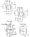
- Fig. 15A is a front elevational view showing a trunnion of the Fig. 13 joint;
- Fig. 15B is a front elevational view showing a trunnion of the Fig. 14 joint;
- Fig. 16 is a cross-sectional view showing a principal portion of a joint for describing dimensions;
- Fig. 17 is a graphic illustration drawn by plotting strength test results;
- Fig. 18 is a bar chart of durability test results;
- Fig. 19A is a partial enlarged illustration of the Fig. 1A joint;
- Fig. 19B is a cross-sectional view taken along a line B-B of Fig. 19A;
- Fig. 20A is a partial front elevational view showing a tripod member;
- Fig. 20B is a partial sectional view showing a constant velocity universal joint incorporating the Fig. 20A tripod member;
- Fig. 21A is a partial front elevational view showing a tripod member;
- Fig. 21B is a partial enlarged illustration of a trunnion shown in Fig. 21A;
- Fig. 22A is a partial front elevational view showing a tripod member;
- Fig. 22B is a cross-sectional view taken along a line X-X of Fig. 22A;
- Fig. 23A is a partial front elevational view showing a tripod member;
- Fig. 23B is a partial sectional view showing the Fig. 23A tripod member equipped with a rolling element and a roller;
- Fig. 24 shows polygonal lines obtained by plotting experimental data, ie induced thrust relative to joint working angle;
- Fig. 25 is a front elevational view in part in section of a tripod member;
- Fig. 26A is an enlarged sectional view showing a roller and rolling elements of the Fig. 25 tripod member;
- Fig. 26B is an enlarged sectional view showing rolling elements and a roller with another construction in the Fig. 25 tripod member;
- Fig. 27 is an illustration for describing an assembling procedure for the Fig. 25 tripod member;
- Fig. 28 is an illustration for describing another assembling procedure for the Fig. 25 tripod member;
- Fig. 29A is an illustration for describing an incorporating procedure for rolling elements for the Fig. 28 roller;
- Fig. 29B is an enlarged view showing a portion of Fig. 29A;
- Fig. 30 is a front elevational view similar to Fig. 25, showing in part in section a tripod member;
- Fig. 31 is a front elevational view similar to Fig. 25, showing in part in section a tripod member; and
- Fig. 32 is a sectional view similar to Fig. 16, showing a modification in which the centers of the trunnion and the roller are offset.
-
- Referring first to Figs. 1A and 1B, a tripod type constant velocity universal joint comprises an
outer member 1 adapted to connect with one of two rotary axes being coupled together by the joint and atripod member 4 adapted to connect with the other of the two axes. Theouter member 1 is gererally cup-shaped and has three circumferentially equispaced, axially extendingtrack grooves 2 formed in an inner circumferential surface. Thetripod member 4 has three circumferentially equispaced, radially protrudingtrunnions 5, each of which rotatably carries aroller 7 with rolling elements therebetween. Therollers 7 are respectively accommodated in thetrack grooves 2 of the outer member. Therollers 7 have cylindrical inner circumferential surface n which is filled through the plurality of rollingelements 6 over an outer circumferential surface m of the trunnion, which surface m in turn is a part of a true sphere with its center p of curvature on the axis of thetrunnion 5. As illustrated the rollingelements 6 have a cylindrical rolling surface whose diameter is relatively large and whose length is not very long as compared with its diameter. In this respect, the rollingelements 6 are in contrast to needle rollers.Washers 8 are attached to both opening end portions of the inner circumferential surface n of the roller to prevent therolling elements 6 from falling out. - As will be seen from Figs. 1B and 2, the gereratrix of an outer circumferential surface of the
roller 7 is a circular arc having its center of curvature at point p spaced apart radially outwardly from the center PR of the roller. Thetrack grooves 2 accommodating therollers 7 extend axially of theouter member 1. A pair of side walls of each of thetrack grooves 2 oppose each other circumferentially of theouter member 1 and provide roller guide surfaces 3 for engagement with the outer circumferential surface of theroller 7. In Figs. 1B and 2 each of the roller guide surfaces 3 is a cylindrical surface with its axis passing point p spaced apart radially outwardly form the center PR of theroller 7. Since the generatrix of the outer circumferential surface of theroller 7 is a circular arc having its center of curvature at a point spaced apart from the center of theroller 7, theroller 7 can hardly incline as viewed in the longitudinal section (Fig. 1A) but runs parallel with the direction in which theroller guide surface 3 extends, i.e. the axial direcion of theouter member 1, ensuring that theroller 7 smoothly rolls on theroller guide surface 3. This is also applicable where the axes being coupled together by the joint are at an angle or the working angle. As shown in Fig. 3, when the joint makes a working angle , thetripod member 4 is inclined by an angle with respect to theouter member 1. At this time, the true-spherical outer circumferential surface m of thetrunnion 5 relatively rolls and moves within the cylindrical inner circumferential surface n of the roller 7 (through the rolling elements 6), while theroller 7 rolls and moves along the roller guide surfaces 3 within thetrack groove 2 while taking a position parallel to the axis of theouter member 1, and in this situation the sliding resistances at the respective portions come down to suppress the occurrence of the induced thrust. The mechanism to reduce the induced thrust when operating in a state with making a working angle is basically the same as that of the two-story roller construction as shown in Figs. 11 and 12, and a description thereof will be taken hereinbelow with reference to Fig. 4. - As indicated by a two-dot chain line in Fig. 4, when the center of the
tripod member 4 at the time of not making a working angle is taken as A, this center A lies on the axis X of theouter member 1, and the center P of the true-spherical outer circumferential surface m of thetrunnion 5 and theroller 7 stands on the center line B of theroller guide surface 3. On the other hand, as shown by a solid line in Fig. 4, when the joint makes a working angle , the center A of thetripod member 4 shifts to a point A' to move downwardly from the axis X in Fig. 4. Consequently, the axis of thetrunnion 5 is inclined by an angle , whereas the center P of the true-spherical outer circumferential surface m relatively moves downwardly from the center line B of theroller guide surface 3 up to a position P' in Fig. 4. Owing to this relative movement and the inclination of thetrunnion 5, the true-spherical outer circumferential surface m of thetrunnion 5 tends to move on the cylindrical inner circumferential surface n of theroller 7 while rotating about the center P, besides this movement is smooth due to the interposition of the rolling elements 6 (omitted in Fig. 4 for clarity; see Fig. 3) therebetween. In accordance with the movement of thetrunnion 5, theroller 7 rolls and moves along theroller guide surface 3 to shift in the direction of the axis X of theouter member 1 parallel to the center line B of theroller guide surface 3 as indicated by an arrow pointing to the right in the illustration. Thus, the relative movement between thetrunnion 5 and theroller 7 and the relative movement between theroller 7 and theroller guide surface 3 are achievable with extremely low resistances, with the result that the occurrence of the induced thrust is suppressible. - In order to ensure that the
roller 7 runs parallel with and rolls on theroller guide surface 3 with a lesser resistance, ashoulder 3a may advantageously be formed so as to extend axially of theouter member 1 along an upper edge of theroller guide surface 3. Theroller 7 always comes into contact at an end surface thereof with theshoulder 3a, and therefore, maintains its position in parallel to the axis of theouter member 1. Thus theroller 7 is guided axially of theouter member 1 as it travels along theroller guide surface 3, resulting in the position of theroller 7 being effectively stabilized even when the joint operates in a state with making a working angle. - The
roller guide surface 3 may be of any shape including the cylindrical shape as described previously. In a modification shown in Fig. 5 the angular contact fashion is adopted in which the outer circumferential surface l of theroller 7 and theroller guide surface 3 come in contact at two points Q and Qspaced apart axially of the
roller 7. Also this arrangement allows theroller 7 to run paralle with the direction in which theroller guide surface 3 extends, that is, the axial direction of theouter member 1. The gap or space confined by theroller guide surface 3 and the roller outer circumferential surface between the two contact points Q and Qroller guide surface 3 can assume a Gothic arch, an ellipse, a parabola, hyperbola or the like. The gereratrix configuration of the outer circumferential surface of theroller 7 can be defined, for example, with a circular arc having a center of curvature on the axis of theroller 7, a circular arc having a center of curvature at a point radially spaced apart from the axis of the roller, either towards or away from the outer circumferential surface of the roller, or a combination of circular arcs having centers of curvature at points spaced apart from each other in the axial direction of theroller 7. - Fig. 6 shows a modification in which a pair of opposing roller guide surfaces 3 constituting side walls of the
track groove 2 are parallel flat surfaces. Along upper and lower edges of each roller guide surface are formedshoulders roller 7 is fitted between the pair ofshoulders roller 7 is engaged with the flat roller guide surfaces 3. In this instance, both the end surfaces of theroller 7 engage with theshoulders roller 7 in the axial direction of theouter member 1 is stably controllable. - As shown as a modification in Fig. 7, it is also appropriate that
annular flanges 9 are integrally formed at both ends of the cylindrical inner surface of theroller 7 to support the rollingelements 6. With this construction, it is possible to omit thewashers 8 for preventing the rolling elements from coming out, which can decrease the number of parts for the roller section. - For using the constant velocity universal joint in a drive system of a motor vehicle, a strength is required which can withstand the drive torque. In general, in the case of the constant velocity universal joint, the strength taken as a criterion or reference depends upon, for example, the strength of a shaft to be coupled to this constant velocity universal joint. Accordingly, for a tripod type constant velocity universal joint (see Fig. 16) of the type that the
trunnion 5 has a true-spherical outer circumferential surface as previously described, a strength test was made from the viewpoint of determining dimensional requirements to satisfy a strength condition. As a result of the test, it was found that two points: the strength of theroller 7 and the strength of the rollingelements 6, exerted influence. For the evaluation, the obtained test result (the strength of the constant velocity universal joint) was divided by the static twisting strength of the shaft to obtain a value c (equation 1) which in turn, was employed as a criterion, and c > 0.93 was determined for clearing the condition. That is, - The geometrical moment of inertia of the
roller 7 greatly has influence on the strength of theroller 7, and the strength of the rollingelements 6 relies upon the diameter of the rolling elements. In order to exclude influence from the sizes (the type number of the joint), the respective dimensions were divided by pitch diameter (herein after PCD) for dimensionless, thus attaining the following conditional equations (2) and (3). - Fig. 17 is an illustration obtained by plotting test data on a plurality of tested joints different in values a and b, where the horizontal scale represents the value a while the vertical scale denotes the value b. Each of the test data includes a mark indicative of an evaluation and values a, b and c. Of the marks representative of the evaluations, the white circle ○ represents "strength OK", that is, satisfying the condition of c > 0.93, the white lozenge ⋄ designates "rolling element no good (NG)", that is, signifying that the rolling element is in poor condition, the black lozenge ◆ denotes that the roller is in poor condition, the black circle depicts "roller and rolling element NG", that is, meaning that both the roller and rolling element are in poor condition, and the cross X stands for "obviously NG", that is, signifying that the shortage of the strength is obvious without making the test.
- As found from Fig. 17, the range of the value of the conditional equation a (equation 2) relating to the
roller 7 is expressed with the mark A, and its lower limit is 0.0281 × 10⁻³. Further, under the conditions that the outer member outer diameter is fixed, the roller outer diameter is enlarged to a maximum and the trunnion journal diameter and the rolling element diameter are set to a minimum so that the roller wall thickness comes to a maximum, according to the calculation the upper limit comes to 1.39 × 10⁻³. From this, the range of a becomes 0.0281 × 10⁻³ < a < 1.39 × 10⁻³. On the other hand, the range of the value of the conditional equation b (equation 3) concerned with the rolling elements is expressed by the mark B, and its lower limit is 0.0417. Further, on the conditions that the outer member outer diameter is fixed, the roller outer diameter is enhanced to a maximum, the trunnion diameter and the roller wall thickness are set to a minimum and the rolling element diameter is maximized, according to the calculation the upper limit amounts to 0.378. From this, the range of b is 0.0417 < b < 0.378. Accordingly, in a manner that a and b are respectively set to within the above-mentioned ranges, the roller and the rolling elements of the constant velocity universal joint for a drive system of a motor vehicle, i.e., the whole joint, can have a sufficient strength. - Furthermore, for the purpose of improving the lubricity of the contact portions to prevent the occurrence of abrasion and peeling of the trunnion journal section, a large number of independent microscopic dents each having a recess shape were made in the surfaces of the rolling
elements 6. In order to meet such a surface roughened condition, a special barrel polishing can be employed as the surface processing therefor, thus obtaining a desirable finished surface. The surface roughness of the rolling elements is Rmax 0.6 to 2.5 µm and the parameter SK value of the surface roughness is below -1.6. Further, the mean area of the dents is 35 to 180 µm2 while the rate of the dents to the entire surface is 10 to 40%. The aforesaid parameter SK value denotes the skewness (strain) of the distribution curve showing the surface roughness. In the case of a symmetrical distribution such as the Gaussian distribution, the parameter SK value becomes 0, and the preferable range of the parameter SK value for providing the shape and distribution of the recesses advantageous to lubricating film formation, although depending on processing conditions, is below -1.6 both in the circumferential direction and in the axial direction. - Fig. 18 shows the results of the endurance tests made in terms of a tripod type constant velocity universal joint in which the outer circumferential surface of the turnnion is a true spherical surface, using the rolling elements subjected to the above-described surface processing and the conventional rolling elements experiencing a superfinishing processing. The test conditions A and B in the same illustration are respectively shown in the following table 1.
Test Condition Bearing Load Speed of Joint Lubricant A 1438 kgf 200 rpm grease B 902 kgf 500 rpm grease - As obvious from the test results of Fig. 18, in the case of the test condition B, the conventional rolling elements come into poor condition at the time of working for 96 hours. On the other hand, the rolling elements according to this invention are still in good condition even after the operating time exceeds more than 160% as compared with the conventional ones. Further, also in the case of the test condition A, the lifetime of the rolling elements according to this invention lengthens more than 200% as compared with the conventional ones. Thus, the above-mentioned surface processing for the rolling elements is effective for the formation of the lubricating film on the rolling element surfaces to enhance the lubricity, so that the rotating performance of the roller can improve and the sliding performance between the rolling elements and the roller and between the rolling elements and the trunnion journal can improve to reduce the occurrence of abrasion and peeling of the contact portions to the utmost.
- Secondly, approach was made to attain a higher performance in the above-described joint shown in Figs. 1A and 1B. That is, in the case of the joint shown in Figs. 1A and 1B, the true-spherical outer circumferential surface m of the
trunnion 5 comes into point contact with the rollingelements 6 so that the surface pressure tends to heighten and the load capacity tends to decrease. The countermeasures to this problem may be enlarging the outer diameter of thetrunnion 5, but resulting in excessively increasing the diameter of the whole joint. In addition, although the number ofrolling elements 6 bearing the load is constant regardless of the magnitude of the working angle, as shown in Figs. 19A and 19B a moment in a direction of a vector M due to thetrunnion 5 acts through the plurality of rollingelements 6 on theroller 7, which makes the position of theroller 7 unstable, whereby difficulty is further encountered in the reduction of the induced thrust. Moreover, the stress easily concentrates on the rollingelements 6 bearing the load irrespective of the magnitude of the working angle, which has influence on the durability of the rolling elements and others. - A description will be made of an embodiment which can solve this problem inherent in the Figs. 1A and 1B joint without increasing the joint size and the number of parts for the joint.
- In an embodiment shown in Figs. 20A and 20B, an outer circumferential surface of each of three trunnions 5 (only one is shown in the illustrations) of a
tripod member 4 is composed of true spherical surfaces m1 having a center of curvature on the axis of thetrunnion 5 and an intermediate curved surface m2 standing at a central portion in the axial direction of thetrunnion 5 having a radius of curvature R2 larger than the radius of curvature R1 of the true spherical surface m1. A cylindrical inner circumferential surface n of aroller 7 is rotatably filled through rollingelements 6 over an outer circumferential surface of thetrunnion 5. Theroller 7 is inserted into atrack groove 2 of anouter member 1 so as to travel axially of theouter member 1 rolling on anroller guide surface 3 of thetrack groove 2. In this case, in other words, the generatrix for the outer circumferential surface of thetrunnion 5 is defined with a combination of circular arcs (m1) lying at both axial ends of thetrunnion 5 and having one and same center of curvature on the axis of thetrunnion 5 to constitute a part of a true circle and a circular arc (m2) having a radius of curvature larger than that of the first-mentioned circular arcs (m1). - The intermediate curved surface m2 of the
trunnion 5 signifies an area where the rollingelements 6 always come into contact at the maximum surface pressure. That is, its width (the dimension in the axial direction) is determined so that the rollingelements 6 principally bearing the load come into contact with the intermediate curved surface m2 when thetripod member 4 transmits torque at the normal working angle (approximately 2 to 10 deg) with respect to theouter member 1. The intermediate curved surface m2 has a gentler curvature than that of the true spherical surface m1, and it is preferable that its radius of curvature R2 is approximately twice to five times the radius of curvature R1 of the true spherical surface m1. The maximum outer diameter of this intermediate curved surface m2 is set to be smaller than the outer diameter of the true spherical surface m1. - Accordingly, in the case that the rolling
elements 6 come into contact with the intermediate curved surface m2 when the joint operates in a state with making a working angle, its maximum surface pressure becomes lower than the maximum surface pressure arises when the rollingelements 6 come into contact with the true spherical surface m1 with a smaller radius of curvature. More specifically, with the true spherical surface m1 having a smaller radius of curvature R1 the rollingelements 6 take a contact state closer to the point contact, while with the intermediate curved surface m2 having a larger radius of curvature R2 it gets into a contact state closer to the line contact, with the result that the reduction of the maximum surface pressure and the increase in the load capacity are possible so that the suppression of the induced thrust and the improvement of the durability are practicable without the increase in the diameter of the whole joint. - A modification shown in Figs. 21A and 21B is characterised in that a cylindrical surface m3 is formed in an intermediate portion of the true spherical surfaces m1 of the
trunnion 5. In other words, the generatrix for the outer circumferential surface of thetrunnion 5 is made with a combination of circular arcs (m1) having a center of curvature on the axis of thetrunnion 5 to constitute a part of a true circle and a straight line (m3). In this instance, the straight line (m3) corresponds to the aforesaid curve (m2) in Fig. 20A with the radius of curvature R2 made infinite. The cylindrical surface m3 is in parallel to the axis of thetrunnion 5 and comes into linear contact with thecylindrical rolling elements 6 and, therefore, the maximum surface pressure is more reducible. In addition, the combination configuration of the true spherical surfaces m1 and the cylindrical surface m3 can more easily be produced as compared with the aforesaid intermediate curved surface m2. - Furthermore, in a modification shown in Figs. 22A and 22B, the outer circumferential surface of the
trunnion 5 of thetripod member 4 is characterised by being a circular arc m4 having a center on the axis as viewed in a longitudinal section (Fig. 22A) but being an ellipse m5 whose minor axis points the load side as viewed in a cross section (Fig. 22B). In Fig. 22B, a dashed line represents the case of a true circle. Although in Fig. 22B it is shown as being an extreme ellipse for easy understanding, the elliptical degree of the ellipse m5 is approximately several tens to 100 µ in the difference between the minor axis (load side) and the major axis (non-loaded side), and all the cross sections perpendicular to the axis of thetrunnion 5 assumes the same difference. Thus, since the transverse cross-sectional configuration of thetrunnion 5 is made to be the ellipse m5 whose minor axis points the load side, as compared with the joint as shown in Figs. 1A and 1B the stress concentration to the rollingelements 6 which come into contact with the load side outer circumferential surface of thetrunnion 5 can be lessened, whereby the maximum surface pressure is reducible and the durability is improvable. - According to the embodiment shown in Figs. 20A and 20B, since the surface portion with a gentler curvature than the true spherical surface at both the end portions of the trunnion exists in the axial central portion of the trunnion of the tripod member, the rolling elements interposed between the trunnion and the roller are mainly brought into contact with the surface portion of the trunnion having the gentler curvature, which contributes to the reduction of the maximum surface pressure of the rolling elements and further to the suppression of the induced thrust, thus providing a tripod type constant velocity universal joint which is capable of making less vibration and creating a high durability. In the case of choosing as an example of the surface portion with a gentler curvature a cylindrical surface corresponding to a curved surface whose radius of curvature is infinite (Figs. 21A and 21B), the surface pressure reduction is further possible. In addition, because the outer circumferential surface of the trunnion is made with a combination of a true spherical surface and a cylindrical surface, the processing is easy to cut down the manufacturing cost of the constant velocity universal joint. Besides, since the transverse cross-sectional configuration of the trunnion of the tripod member assumes an ellipse whose minor axis points the load side (Figs. 22A and 22B), the stress concentration on the rolling elements contacting with the trunnion can be mitigated, thereby providing a tripod type constant velocity universal joint which is excellent in the reduction of the induced thrust and the durability.
- Incidentally, it is also possible to add the intermediate curved surface, the cylindrical surface and the like, already described with reference to Figs. 20A, 20B, 21A and 21B, to the axial central portion of the
trunnion 5 shown in Figs. 22A and 22B. In this case, owing to the multiplier effects of the respective structures, the durability can further improve. - Figs. 23A and 23B show a modification in which the outer circumferential surface of the
trunnion 5 is made to be the so-called torus surface m6. For this torus surface m6, a circular arc having a center at a point spaced radially outwardly from the axis of thetrunnion 5 and having a radius R3 is used as the generatrix and the axial central portion of thetrunnion 5 assumes the largest outer diameter (2R1). Although the structure shown in Figs. 23A and 23B goes against the surface pressure reduction, the torus surface m6 of thetrunnion 6 comes into contact with the rollingelement 6 with a frictional resistance smaller than that in the case of a true spherical surface (for comparison, a circular arc R1 having a center of curvature on the axis of thetrunnion 5 is indicated with a dotted line in Fig. 23B), with the result that the suppression of the induced thrust becomes easier. In addition, when the joint operates in a state with making a working angle, the number ofrolling elements 6 bearing the load decreases in accordance with the difference in radius [R1 - R3], and accordingly the vector M direction moment receiving from thetrunnion 5 and working on theroller 7 decreases to stabilize the position of theroller 7 as compared with the case of the true spherical surface, with the result that the induced thrust is reducible. In this case, it is necessary that the difference in radius [R1 - R3] is set to approximately 1 to 2 mm so as not to increase the surface pressure. - Fig. 24 shows the results of the measurement of the induced thrust in the case of the embodiment shown in Figs. 1A and 1B and the modification shown in Figs. 23A and 23B. In this case, in the modification the outer circumferential surface of the
trunnion 5 is the torus surface m6 of the maximum radius R1 = 19.095 mm and the generatrix radius R3 = 17.85 mm, while in the embodiment of Figs. 1A and 1B the outer circumferential surface of the trunnion is a true spherical surface having the radius of curvature of 19.095 mm. As shown in Fig. 24, the induced thrust takes the relation of the embodiment < the modification until the working angle taken when in operation rises up to approximately 6 deg, while in the range of the working angle exceeding 6 deg the induced thrust takes, on the contrary, the relation of the embodiment > the modification. - Accordingly, in the case of the structure shown in Figs. 23A and 23B, if the curvature of the intermediate portion of the torus surface m6 coming into contact with the rolling
elements 6 in the range of the working angle within 6 deg is made to be relaxed to approximately the curvature of the true spherical surface so that this intermediate portion becomes similar to the intermediate curved surface or the cylindrical surface in the embodiment shown in Figs. 1A and 1B or Fig. 2, even if the working angle is below 6 deg, the induced thrust is reducible up to those in the above-described embodiments or to below those values. - Conventionally, the outer circumferential surface of the
trunnion 11 of thetripod member 4 is, for example, a cylindrical surface as shown in Fig. 8C, and aninner washer 14 is filled over the proximal portion of this cylindrical surface and anouter washer 15 and aclip 16 are fitted over the tip portion thereof, and further a plurality of rolling elements are placed between both thewashers elements 6 are serially arranged along the outer circumference of thetrunnion 5 without making gaps therebetween. Theouter washer 15 is placed into contact with an end surface of the rollingelements 12 to limit the axial position of the rollingelements 12 and further to prevent them from falling out. Theclip 16 is filled in agroove 17 made in the outer circumference of thetrunnion 11 to fix theouter washer 15 against thetrunnion 11. For assembling atripod member 4 shown in Fig. 8C, a plurality of rollingelements 12 are successively arranged on the outer circumference of thetrunnion 11 and then aroller 13 is fitted over them, or alternatively, theroller 13 is fitted over thetrunnion 11 and the plurality of rolling elements are inserted into an annular space formed between thetrunnion 11 and theroller 13. However, both the cases require a large number of steps for assembling and are hard to assemble, thus deteriorating the assembling working efficiency of the tripod type constant velocity universal joint. Further, theouter washer 15 for preventing the rolling elements mounted on thetrunnion 11 from falling out is required to have a special shape as shown in the illustration for also preventing theroller 13 from coming out, and theclip 16 for setting theouter washer 15 on thetrunnion 11 is additionally necessary, with the result that the number of parts for thetripod member 4 and the number of assembling steps become many so that difficulty is encountered to lower the manufacturing cost thereof. - Referring now to Figs. 25 to 31 a description will be made hereinbelow of a tripod type constant velocity universal joint according to an embodiment of this invention which can eliminate the above-mentioned problems and which is capable of improving the assembling working efficiency and lowering the manufacturing cost.
- In a
tripod member 4 shown in Fig. 25, astopper 10 for preventing a plurality of rollingelements 6 from falling out is formed on an inner circumferential surface of aroller 7 fitted through the rollingelements 6 over the outer circumference of each oftrunnions 5. For example, the outer circumferential surface of thetrunnion 5 is a cylindrical surface, and a plurality of cylindricalrolling elements 6 such as rollers and needle rollers are serially disposed on this cylindrical outer circumferential surface without defining gaps therebetween, and the cylindrical inner circumferential surface of theroller 7 is located around these rollingelements 6. - Concrete examples of the
stoppers 10 to be formed on the cylindrical inner circumferential surface of theroller 7 are shown in Figs. 26A and 26B. In Fig. 26A, thestoppers 10 are in the form of a pair ofannular step portions 9 formed at both ends of theroller 7 to protrude from the cylindrical inner circumferential surface of theroller 7. For instance, a groove for accommodating therolling elements 6 for rolling motion is formed in a central section of the cylindrical inner circumferential surface of theroller 7 so that the axial end portions thereof define the inwardly protrudingannular steps 9. Alternatively, in Fig. 26B, thestoppers 10 are in the form of a pair ofwashers 8 filled ingrooves 8a formed in both axial end portions of the cylindrical inner circumferential surface of theroller 7. The protruding amount of thewasher 8 from the roller cylindrical inner circumferential surface corresponds to the step (difference in level) of theannular step 9 in Fig. 26A. - Thanks to the provision of the rolling element falling-out preventing
stoppers 10 on the cylindrical inner circumferential surface of theroller 7, the assembling ways as shown in Figs. 27 and 28 are selectively acceptable. - When attaching the
roller 7 of Fig. 26A to thetrunnion 5, as shown in Fig. 27 theroller 7, together with the rollingelements 6, is fitted over thetrunnion 5 in a state where all therolling elements 6 are serially arranged along and temporarily adhered to the cylindrical inner circumferential surface of theroller 7 with agrease 10a. Thegrease 10a is of the well-known type for lubricating the rolling elements, and thisgrease 10a is applied in advance to the cylindrical inner circumferential surface of theroller 7 to make a desired thickness thereon and the rollingelements 6 are pressed against the appliedgrease 10a so that the plurality of rollingelements 6 are subjected to the temporary adhesion. Thereafter, theroller 7, together with the rollingelements 6, is filled over the cylindrical outer circumferential surface of thetrunnion 5, with the result that the stoppers 10 (9) of theroller 7 prevent therolling elements 6 from coming out and the attachment of theroller 7 and the rollingelements 6 to thetrunnion 5 can surely and smoothly be done. - Fig. 28 shows a method in which the
roller 7, together with a plurality of rollingelements 6, is mounted over thetrunnion 5 in a state that the rollingelements 6 are temporarily serially attached to the cylindrical inner circumferential surface of theroller 7 according to the so-called Keystone method. For example, as shown in Figs. 29A and 29B all therolling elements 6 but one are serially arranged on the cylindrical inner circumferential surface of theroller 7, and thelast one 6 is forced into a gap g defined between the two of this series of rollingelements 6 positioned at both the ends thereof. In this case, the relation between the diameter d1 of the rollingelements 6 and the minimum separation d2 of the gap g is set to be d1 > d2, the difference [d1 - d2] being an interference of several µ to several tens µ. Thus, now that the lastone rolling element 6 is fitted in the gap g under pressure, all therolling elements 6 are temporarily and serially held on the cylindrical inner circumferential surface of theroller 7. Also in the case of Fig. 28, when theroller 7, together with the rollingelements 6, is fitted over the cylindrical outer circumferential surface of thetrunnion 5, the stoppers 10 (9) of theroller 7 prevent the falling-out of the rollingelements 6 and the mounting of theroller 7 and the rollingelements 6 on thetrunnion 5 is surely and smoothly achievable. In addition, the plurality of rollingelements 6 attached in advance to theroller 7 according to the Keystone method can smoothly rotate between theroller 7 and thetrunnion 5 with no problem as long as having the above-mentioned interference. - As described above, the work for setting the unit, in which the rolling
elements 6 are combined with theroller 7, to thetrunnion 5 to assemble thetripod member 4 is technically easier as compared with the conventional assembling work, and its number of working steps for assembling decreases, thus further improving the assembling working efficiency. In addition, in the case that like theroller 7 as shown in Fig. 26A the stoppers 10 (9) are integrally formed on the roller cylindrical inner circumferential surface, since it is possible to omit the washers or clips for preventing the rolling elements fitted over the trunnion from falling out, the number of parts for thetripod member 4 and the number of steps for assembling are reducible, thus easily culling down the manufacturing cost. - Also in the case that like the
roller 7 shown in Fig. 26B thestoppers 10 are constructed using thewashers 8, it is possible to assemble the tripod member through the use of the adhering method based on the grease in Fig. 27 and through the use of the Keystone method in Fig. 28. In theroller 7 of Fig. 26B, since the pair ofwashers 8 is employed in order to prevent the rolling elements from falling out, although there is no effect to cut down the number of parts, thewashers 8 can be constructed with cheap flat washers with a simple configuration which merely protrude from the cylindrical inner circumferential surface of theroller 7, so that it is possible to cut down the manufacturing cost of the tripod member. - The structure of the tripod member and the assembling method thereof described with reference to Figs. 25 to 28, 29A and 29B are also applicable to the embodiment of Figs. 1A and 1B, the modifications thereof, the embodiment of Figs. 20A and 20B and the modifications thereof with the same effects. For example, the outer circumferential surface of the
trunnion 5 of thetripod member 4 shown in Fig. 30 is a true spherical surface having its center P1 on the axis of thetrunnion 5 and having a radius R1, and the rollingmembers 6 are brought into point contact with this true spherical surface to be slidable, and further theroller 7 is pivotably mounted relative to thetrunnion 5. Further, the outer circumferential surface of thetrunnion 5 of thetripod member 4 shown in Fig. 31 has a circular generatrix whose center P2 is separated from the axis of thetrunnion 5 and whose radius is R2. The rollingelements 6 are placed into point contact with this outer circumferential surface to be slidable, and theroller 7 is pivotably mounted relatively to thetrunnion 5. - Taking Figs. 4 and 16 for example, the center of the
trunnion 5 and the center of theroller 7 are shown as coexisting with each other as at point P even when the two axes being coupled together by the joint are not at an angle, though, they may be offset axially of thetrunnion 5. When the axes being coupled by the joint are at an angle, the center P of thetrunnion 5 shifts towards the axis X of theouter member 4, i.e., from P to P', as previously described in conjunction with Fig. 4, and therfore, the centers of thetrunnion 5 androller 7 are offset axially of thetrunnion 7. In order to obviate such problem, as shown in Fig. 32, the center PR of the roller may be spaced apart from the center P of thetrunnion 5 by a predetermdined amount towards the axis X of theouter member 4; this ensures that when the axes being coupled by the joint are at an angle, the center P of thetrunnion 5 shifts towards the axis X of theouter member 1 to coincide with or approach the center of theroller 7. This arrangement takes account of the movements encountered by the components of the joint in transmitting torque between the two rotary axes which are at an angle, and its significance will be apparent in view of the fact that in the joint of this kind the two rotary axes being coupled are usually at an angle. - It should be understood that the foregoing relates to only preferred embodiments of the present invention, and that it is intended to cover all changes and modifications of the embodiments of the invention herein used for the purposes of the disclosure, which do not constitute departures from the spirit and scope of the invention.
Claims (7)
- A tripod type constant velocity universal joint comprising:an outer member (1) having three axially extending track grooves (2) formed in an inner circumferential surface thereof, each of the track grooves (2) having roller guide surfaces on a pair of opposing side walls thereof,a tripod-member (4) having three radially projecting trunnions (5) androllers (7) rotatably carried on the trunnions (4), respectively, through a series of cylindrical rolling elements (6), the rollers (7) being accommodated in the track grooves (2), respectively, so that the rollers (7) are movable axially of the outer member (1) with each said roller (7) rolling along one of the opposing roller guide surfaces,
wherein each said roller (7) with an annular projection at an end thereof and a series of said rolling elements retained along an inner periphery of said roller form an assembly capable of preventing said rolling elements from dispersing even before the assembly is mounted on a respective trunnion (5). - A tripod type constant velocity universal joint as set forth in claim 1, wherein a generatrix of an outer circumferential surface of the trunnion (5) is a curve.
- A tripod type constant velocity universal joint as set forth in claim 1, wherein a generatrix of an outer circumferential surface of the trunnion (5) is a substantially straight line parallel to the axis of the trunnion (5).
- A tripod type constant velocity universal joint as set forth in claim 1, wherein the cylindrical rolling elements (6) are stuck with grease (10a) on an inner peripheral surface of the roller.
- A tripod type constant velocity universal joint as set forth in claim 1, wherein the cylindrical rolling elements (6) are locked in position along an inner periphery of the roller with one rolling element serving as keystone.
- A tripod type constant velocity joint as set forth in any of claims 1 to 5 wherein the inner circumferential surface of the roller (7) is cylindrical and the outer surface of the roller (7) is defined, at opposite ends of the trunnion (5), by circular arcs.
- A method of manufacturing a tripod type constant velocity joint wherein rollers (7) rotatably carried, through cylindrical rolling elements (6), on three trunnions (5) of a tripod member (4) are accommodated, respectively, in track grooves (2) formed in an inner circumferential surface of an outer member (1) in an axial direction, so that the rollers (7) are movable axially of the outer member along roller guide surfaces at opposite sides of each of the track grooves (2) and extending axially of the outer member (1), said method comprising the steps of:providing an annular projection on an inner circumferential surface of said roller (7) to prevent said plurality of cylindrical rolling elements (6) from falling out in their axial direction,serially arranging said plurality of rolling elements (6) but one on said roller inner circumferential surface along said annular projection,forcing the last one rolling element (6) into a gap between the two of both ends of the serially arranged rolling elements (6), and fitting said roller (7), together with said plurality of rolling elements (6) over said trunnion (5).
Applications Claiming Priority (9)
| Application Number | Priority Date | Filing Date | Title |
|---|---|---|---|
| JP1910696 | 1996-02-05 | ||
| JP1910696 | 1996-02-05 | ||
| JP34764796 | 1996-12-26 | ||
| JP34765596 | 1996-12-26 | ||
| JP34765596A JP3385343B2 (en) | 1996-12-26 | 1996-12-26 | Tripod type constant velocity universal joint |
| JP34761296A JP3917227B2 (en) | 1996-12-26 | 1996-12-26 | Tripod type constant velocity universal joint |
| JP34761296 | 1996-12-26 | ||
| JP34764796 | 1996-12-26 | ||
| EP97901808A EP0836023B1 (en) | 1996-02-05 | 1997-01-31 | Tri-pod constant velocity universal joint |
Related Parent Applications (1)
| Application Number | Title | Priority Date | Filing Date |
|---|---|---|---|
| EP97901808A Division EP0836023B1 (en) | 1996-02-05 | 1997-01-31 | Tri-pod constant velocity universal joint |
Publications (3)
| Publication Number | Publication Date |
|---|---|
| EP1008777A2 true EP1008777A2 (en) | 2000-06-14 |
| EP1008777A3 EP1008777A3 (en) | 2000-06-21 |
| EP1008777B1 EP1008777B1 (en) | 2007-04-25 |
Family
ID=27457119
Family Applications (2)
| Application Number | Title | Priority Date | Filing Date |
|---|---|---|---|
| EP00101847A Expired - Lifetime EP1008777B1 (en) | 1996-02-05 | 1997-01-31 | Tripod type constant velocity universal joint |
| EP97901808A Expired - Lifetime EP0836023B1 (en) | 1996-02-05 | 1997-01-31 | Tri-pod constant velocity universal joint |
Family Applications After (1)
| Application Number | Title | Priority Date | Filing Date |
|---|---|---|---|
| EP97901808A Expired - Lifetime EP0836023B1 (en) | 1996-02-05 | 1997-01-31 | Tri-pod constant velocity universal joint |
Country Status (7)
| Country | Link |
|---|---|
| US (1) | US5989124A (en) |
| EP (2) | EP1008777B1 (en) |
| KR (1) | KR19980703608A (en) |
| AU (1) | AU1557597A (en) |
| DE (2) | DE69737661T2 (en) |
| TW (1) | TW486552B (en) |
| WO (1) | WO1997029294A1 (en) |
Cited By (7)
| Publication number | Priority date | Publication date | Assignee | Title |
|---|---|---|---|---|
| EP1253337A1 (en) * | 2001-04-25 | 2002-10-30 | Ntn Corporation | Constant velocity joint |
| WO2003095857A1 (en) * | 2002-05-08 | 2003-11-20 | Sobhy Lahib Girguis | Synchronized sliding joint |
| EP1691091A1 (en) * | 2003-11-18 | 2006-08-16 | HONDA MOTOR CO., Ltd. | Constant velocity joint and method of manufacturing the same |
| EP2105491A1 (en) * | 2006-12-11 | 2009-09-30 | NTN Corporation | Lubricating system, bearing utilizing the system, universal joint utilizing the system, and process for production thereof |
| WO2012010375A1 (en) * | 2010-07-21 | 2012-01-26 | Schaeffler Technologies Gmbh & Co. Kg | Tripod constant velocity joint |
| DE102013106868B3 (en) * | 2013-07-01 | 2014-10-30 | Gkn Driveline International Gmbh | Inner joint part and roller body of a tripod constant velocity joint |
| DE102021210452A1 (en) | 2021-09-21 | 2023-03-23 | Volkswagen Aktiengesellschaft | tripod star |
Families Citing this family (19)
| Publication number | Priority date | Publication date | Assignee | Title |
|---|---|---|---|---|
| FR2785342B1 (en) * | 1998-11-02 | 2002-05-10 | Ntn Toyo Bearing Co Ltd | UNIVERSAL HOMOCINETIC JOINT |
| JP3599618B2 (en) * | 1999-03-05 | 2004-12-08 | Ntn株式会社 | Constant velocity universal joint |
| FR2791745A1 (en) * | 1999-03-31 | 2000-10-06 | Gkn Glaenzer Spicer | Needle bearing assembly for a constant velocity joint in a motor vehicle transmission, comprises of split washers retaining inner ring and needle bearing assemblies |
| US6478682B1 (en) * | 1999-11-05 | 2002-11-12 | Ntn Corporation | Constant velocity universal joint |
| US6632143B2 (en) | 2000-03-31 | 2003-10-14 | Ntn Corporation | Constant velocity universal joint |
| JP2001295855A (en) * | 2000-04-13 | 2001-10-26 | Ntn Corp | Uniform universal coupling |
| JP2002054649A (en) * | 2000-08-11 | 2002-02-20 | Ntn Corp | Tripod type constant velocity universal joint |
| JP3817415B2 (en) * | 2000-09-06 | 2006-09-06 | Ntn株式会社 | Constant velocity universal joint |
| JP4334754B2 (en) * | 2000-10-13 | 2009-09-30 | デルファイ・テクノロジーズ・インコーポレーテッド | Tripod type constant velocity joint |
| US6699134B2 (en) | 2001-02-21 | 2004-03-02 | Visteon Global Technologies, Inc. | Anti-shudder tripod type CV universal joint |
| US6776719B2 (en) * | 2002-06-14 | 2004-08-17 | Delphi Technologies, Inc. | Tripot universal joint |
| US20060211502A1 (en) * | 2003-04-08 | 2006-09-21 | Honda Motor Co., Ltd. | Constant velocity joint and method of manufacturing the same |
| WO2005083283A1 (en) * | 2004-03-02 | 2005-09-09 | Honda Motor Co., Ltd. | Constant velocity joint |
| TWI260376B (en) * | 2004-05-18 | 2006-08-21 | Honda Motor Co Ltd | Constant-velocity joint and method of manufacturing same |
| US7371179B2 (en) * | 2005-06-23 | 2008-05-13 | Honda Motor Co., Ltd. | Tripod constant-velocity universal joint |
| US7435181B2 (en) * | 2005-10-25 | 2008-10-14 | Delphi Technologies, Inc. | Tripot ball with two point contact |
| KR100815677B1 (en) * | 2006-05-11 | 2008-03-20 | 위아 주식회사 | tripod type constant velocity joint |
| DE102009041086A1 (en) | 2009-09-10 | 2011-03-24 | Volkswagen Ag | Tripod star for use in tripod joint, has pivots, where middle point of larger in-circle lies on longitudinal axes of pivots and surface line of circumferential surface runs in plane between another surface line and in-circle |
| JP7398310B2 (en) | 2020-03-26 | 2023-12-14 | 本田技研工業株式会社 | constant velocity joint |
Citations (2)
| Publication number | Priority date | Publication date | Assignee | Title |
|---|---|---|---|---|
| US4379706A (en) | 1978-04-05 | 1983-04-12 | Honda Giken Kogyo Kabushiki Kaisha | Slidable-type constant velocity universal joint |
| US4786270A (en) | 1986-09-17 | 1988-11-22 | Ntn Toyo Bearing Co., Ltd. | Homokinetic tripod joint |
Family Cites Families (21)
| Publication number | Priority date | Publication date | Assignee | Title |
|---|---|---|---|---|
| US1907015A (en) * | 1931-11-19 | 1933-05-02 | Rollway Bearing Company Inc | Antifriction bearing |
| FR833387A (en) * | 1938-02-08 | 1938-10-20 | Rossi Freres Ets | Method of mounting bearings, and bearings thus established |
| FR1391770A (en) * | 1963-11-30 | 1965-03-12 | Glaenzer Spicer Sa | Insert cheek device for roller or needle bearings |
| JPS5354645A (en) * | 1976-10-27 | 1978-05-18 | Ntn Toyo Bearing Co Ltd | Uniform velocity universal joint |
| FR2506873B1 (en) * | 1981-06-01 | 1986-08-22 | Glaenzer Spicer Sa | AXIAL RETAINING TRIPOD JOINT |
| FR2506874B1 (en) * | 1981-06-01 | 1986-08-29 | Glaenzer Spicer Sa | HOMOCINETIC JOINT WITH TRIPOD WITH ROTATING ROLLERS |
| US4589856A (en) * | 1985-02-28 | 1986-05-20 | The Zeller Corporation | Tripot universal joint of the end motion type |
| US4810232A (en) * | 1987-01-28 | 1989-03-07 | General Motors Corporation | Telescopic tripot universal joint |
| GB8827655D0 (en) * | 1988-11-26 | 1988-12-29 | Spicer Hardy Ltd | Constant velocity ratio universal joints |
| JPH03121228U (en) * | 1990-03-26 | 1991-12-12 | ||
| DE4034758C2 (en) * | 1990-11-02 | 1995-01-05 | Gkn Automotive Ag | Tripod joint |
| DE4102001C2 (en) * | 1991-01-24 | 1999-02-04 | Girguis Sobhy Labib | Constant velocity joint |
| DE4130183C2 (en) * | 1991-09-11 | 1994-01-20 | Gkn Automotive Ag | Tripod joint |
| JP2618165B2 (en) * | 1992-10-28 | 1997-06-11 | 本田技研工業株式会社 | Sliding universal joint |
| ES2088759B1 (en) * | 1992-12-08 | 1998-08-01 | Gkn Automotive Ag | SYNCHRONOUS SWIVEL JOINT |
| DE9218285U1 (en) * | 1992-12-08 | 1994-04-07 | Gkn Automotive Ag | Workpiece made by forming |
| DE4408812A1 (en) * | 1993-03-24 | 1994-09-29 | Schaeffler Waelzlager Kg | Pivoting bearing |
| DE4327036A1 (en) * | 1993-08-12 | 1995-02-16 | Gkn Automotive Ag | Synchronous swivel joint |
| JPH08145070A (en) * | 1994-11-25 | 1996-06-04 | Mitsubishi Automob Eng Co Ltd | Tripod type constant velocity joint |
| JP3043280B2 (en) * | 1996-02-15 | 2000-05-22 | 本田技研工業株式会社 | Constant velocity joint |
| JP4018785B2 (en) * | 1998-01-26 | 2007-12-05 | 本田技研工業株式会社 | Constant velocity joint and manufacturing method thereof |
-
1997
- 1997-01-31 EP EP00101847A patent/EP1008777B1/en not_active Expired - Lifetime
- 1997-01-31 AU AU15575/97A patent/AU1557597A/en not_active Abandoned
- 1997-01-31 DE DE69737661T patent/DE69737661T2/en not_active Expired - Lifetime
- 1997-01-31 WO PCT/JP1997/000243 patent/WO1997029294A1/en active IP Right Grant
- 1997-01-31 EP EP97901808A patent/EP0836023B1/en not_active Expired - Lifetime
- 1997-01-31 DE DE69733180T patent/DE69733180T2/en not_active Expired - Lifetime
- 1997-01-31 KR KR1019970707007A patent/KR19980703608A/en not_active Application Discontinuation
- 1997-01-31 US US08/894,792 patent/US5989124A/en not_active Expired - Lifetime
- 1997-02-05 TW TW088118810A patent/TW486552B/en active
Patent Citations (2)
| Publication number | Priority date | Publication date | Assignee | Title |
|---|---|---|---|---|
| US4379706A (en) | 1978-04-05 | 1983-04-12 | Honda Giken Kogyo Kabushiki Kaisha | Slidable-type constant velocity universal joint |
| US4786270A (en) | 1986-09-17 | 1988-11-22 | Ntn Toyo Bearing Co., Ltd. | Homokinetic tripod joint |
Cited By (13)
| Publication number | Priority date | Publication date | Assignee | Title |
|---|---|---|---|---|
| EP1253337A1 (en) * | 2001-04-25 | 2002-10-30 | Ntn Corporation | Constant velocity joint |
| US6733394B2 (en) | 2001-04-25 | 2004-05-11 | Ntn Corporation | Constant velocity joint |
| WO2003095857A1 (en) * | 2002-05-08 | 2003-11-20 | Sobhy Lahib Girguis | Synchronized sliding joint |
| US7597627B2 (en) | 2003-11-18 | 2009-10-06 | Honda Motor Co., Ltd. | Constant velocity joint and method of manufacturing the same |
| EP1691091A4 (en) * | 2003-11-18 | 2007-08-29 | Honda Motor Co Ltd | Constant velocity joint and method of manufacturing the same |
| EP1691091A1 (en) * | 2003-11-18 | 2006-08-16 | HONDA MOTOR CO., Ltd. | Constant velocity joint and method of manufacturing the same |
| EP2105491A1 (en) * | 2006-12-11 | 2009-09-30 | NTN Corporation | Lubricating system, bearing utilizing the system, universal joint utilizing the system, and process for production thereof |
| EP2105491A4 (en) * | 2006-12-11 | 2011-03-16 | Ntn Toyo Bearing Co Ltd | Lubricating system, bearing utilizing the system, universal joint utilizing the system, and process for production thereof |
| US8333665B2 (en) | 2006-12-11 | 2012-12-18 | Ntn Corporation | Lubricating system, bearing utilizing the system, universal joint utilizing the system, and process for production thereof |
| WO2012010375A1 (en) * | 2010-07-21 | 2012-01-26 | Schaeffler Technologies Gmbh & Co. Kg | Tripod constant velocity joint |
| DE102013106868B3 (en) * | 2013-07-01 | 2014-10-30 | Gkn Driveline International Gmbh | Inner joint part and roller body of a tripod constant velocity joint |
| US10100877B2 (en) | 2013-07-01 | 2018-10-16 | Gkn Driveline International Gmbh | Inner joint part and roller element of a tripod constant velocity joint |
| DE102021210452A1 (en) | 2021-09-21 | 2023-03-23 | Volkswagen Aktiengesellschaft | tripod star |
Also Published As
| Publication number | Publication date |
|---|---|
| EP1008777A3 (en) | 2000-06-21 |
| DE69733180T2 (en) | 2006-02-02 |
| EP1008777B1 (en) | 2007-04-25 |
| AU1557597A (en) | 1997-08-28 |
| DE69737661D1 (en) | 2007-06-06 |
| TW486552B (en) | 2002-05-11 |
| KR19980703608A (en) | 1998-12-05 |
| EP0836023A1 (en) | 1998-04-15 |
| DE69737661T2 (en) | 2008-01-03 |
| EP0836023A4 (en) | 1999-04-07 |
| US5989124A (en) | 1999-11-23 |
| WO1997029294A1 (en) | 1997-08-14 |
| EP0836023B1 (en) | 2005-05-04 |
| DE69733180D1 (en) | 2005-06-09 |
Similar Documents
| Publication | Publication Date | Title |
|---|---|---|
| EP0836023B1 (en) | Tri-pod constant velocity universal joint | |
| US5203741A (en) | Constant velocity ratio universal joint with gothic arch shaped rollers and guide grooves | |
| US7682253B2 (en) | Tripod type constant velocity joint | |
| US6533668B2 (en) | Constant velocity joint of tripod type | |
| US6497621B2 (en) | Constant velocity universal joint and method for assembling the same | |
| JP3043280B2 (en) | Constant velocity joint | |
| US6764406B2 (en) | Constant velocity joint of tripod type | |
| US8535167B2 (en) | Constant velocity joint of tripod type | |
| JP4015822B2 (en) | Constant velocity universal joint | |
| US8608578B2 (en) | Constant velocity joint of tripod type | |
| US6837794B1 (en) | Tripod type constant velocity universal joint | |
| CA2368564C (en) | Constant velocity universal joint | |
| US7878914B2 (en) | Constant velocity joint of tripod type | |
| JP3905943B2 (en) | Tripod type constant velocity universal joint | |
| JP3913380B2 (en) | Constant velocity joint and its assembly method | |
| WO2021246129A1 (en) | Tripod-type constant-velocity universal joint | |
| JPH064103Y2 (en) | Constant velocity universal joint | |
| JP3976358B2 (en) | Tripod type constant velocity joint | |
| JPH0121369B2 (en) | ||
| JP2001234940A (en) | Constant velocity joint |
Legal Events
| Date | Code | Title | Description |
|---|---|---|---|
| PUAI | Public reference made under article 153(3) epc to a published international application that has entered the european phase |
Free format text: ORIGINAL CODE: 0009012 |
|
| PUAL | Search report despatched |
Free format text: ORIGINAL CODE: 0009013 |
|
| AC | Divisional application: reference to earlier application |
Ref document number: 836023 Country of ref document: EP |
|
| AK | Designated contracting states |
Kind code of ref document: A2 Designated state(s): DE FR GB IT |
|
| AK | Designated contracting states |
Kind code of ref document: A3 Designated state(s): DE FR GB IT |
|
| RIC1 | Information provided on ipc code assigned before grant |
Free format text: 7F 16D 3/205 A, 7F 16C 43/06 B |
|
| RIN1 | Information on inventor provided before grant (corrected) |
Inventor name: OZAWA, MASAHIRO Inventor name: SAITO, TSUYOSHI Inventor name: GOTO, TATUHIRO Inventor name: NAGATANI, HARUO |
|
| 17P | Request for examination filed |
Effective date: 20000707 |
|
| 17Q | First examination report despatched |
Effective date: 20000915 |
|
| AKX | Designation fees paid |
Free format text: DE FR GB IT |
|
| GRAP | Despatch of communication of intention to grant a patent |
Free format text: ORIGINAL CODE: EPIDOSNIGR1 |
|
| GRAS | Grant fee paid |
Free format text: ORIGINAL CODE: EPIDOSNIGR3 |
|
| GRAA | (expected) grant |
Free format text: ORIGINAL CODE: 0009210 |
|
| AC | Divisional application: reference to earlier application |
Ref document number: 0836023 Country of ref document: EP Kind code of ref document: P |
|
| AK | Designated contracting states |
Kind code of ref document: B1 Designated state(s): DE FR GB IT |
|
| REG | Reference to a national code |
Ref country code: GB Ref legal event code: FG4D |
|
| REF | Corresponds to: |
Ref document number: 69737661 Country of ref document: DE Date of ref document: 20070606 Kind code of ref document: P |
|
| ET | Fr: translation filed | ||
| PLBE | No opposition filed within time limit |
Free format text: ORIGINAL CODE: 0009261 |
|
| STAA | Information on the status of an ep patent application or granted ep patent |
Free format text: STATUS: NO OPPOSITION FILED WITHIN TIME LIMIT |
|
| 26N | No opposition filed |
Effective date: 20080128 |
|
| REG | Reference to a national code |
Ref country code: FR Ref legal event code: PLFP Year of fee payment: 20 |
|
| PGFP | Annual fee paid to national office [announced via postgrant information from national office to epo] |
Ref country code: FR Payment date: 20151208 Year of fee payment: 20 |
|
| PGFP | Annual fee paid to national office [announced via postgrant information from national office to epo] |
Ref country code: DE Payment date: 20160127 Year of fee payment: 20 Ref country code: IT Payment date: 20160127 Year of fee payment: 20 |
|
| PGFP | Annual fee paid to national office [announced via postgrant information from national office to epo] |
Ref country code: GB Payment date: 20160127 Year of fee payment: 20 |
|
| REG | Reference to a national code |
Ref country code: DE Ref legal event code: R071 Ref document number: 69737661 Country of ref document: DE |
|
| REG | Reference to a national code |
Ref country code: GB Ref legal event code: PE20 Expiry date: 20170130 |
|
| PG25 | Lapsed in a contracting state [announced via postgrant information from national office to epo] |
Ref country code: GB Free format text: LAPSE BECAUSE OF EXPIRATION OF PROTECTION Effective date: 20170130 |