EP1007904B1 - Method and device for measuring an envelope surface - Google Patents
Method and device for measuring an envelope surface Download PDFInfo
- Publication number
- EP1007904B1 EP1007904B1 EP98939039A EP98939039A EP1007904B1 EP 1007904 B1 EP1007904 B1 EP 1007904B1 EP 98939039 A EP98939039 A EP 98939039A EP 98939039 A EP98939039 A EP 98939039A EP 1007904 B1 EP1007904 B1 EP 1007904B1
- Authority
- EP
- European Patent Office
- Prior art keywords
- measuring
- support member
- carriage
- measuring device
- envelope surface
- Prior art date
- Legal status (The legal status is an assumption and is not a legal conclusion. Google has not performed a legal analysis and makes no representation as to the accuracy of the status listed.)
- Expired - Lifetime
Links
- 238000000034 method Methods 0.000 title claims abstract description 21
- 238000005259 measurement Methods 0.000 claims abstract description 44
- 230000001681 protective effect Effects 0.000 claims abstract description 21
- 239000000463 material Substances 0.000 claims description 10
- 230000008878 coupling Effects 0.000 claims description 9
- 238000010168 coupling process Methods 0.000 claims description 9
- 238000005859 coupling reaction Methods 0.000 claims description 9
- 230000005540 biological transmission Effects 0.000 claims description 8
- 230000001939 inductive effect Effects 0.000 claims description 7
- 239000004033 plastic Substances 0.000 claims description 6
- 229910052751 metal Inorganic materials 0.000 claims description 5
- 239000002184 metal Substances 0.000 claims description 5
- 230000007797 corrosion Effects 0.000 claims description 4
- 238000005260 corrosion Methods 0.000 claims description 4
- 125000006850 spacer group Chemical group 0.000 claims description 4
- 230000001360 synchronised effect Effects 0.000 claims description 4
- 239000002131 composite material Substances 0.000 claims description 3
- 239000000919 ceramic Substances 0.000 claims description 2
- 230000001427 coherent effect Effects 0.000 claims description 2
- 238000004519 manufacturing process Methods 0.000 claims description 2
- 230000001105 regulatory effect Effects 0.000 claims 1
- 238000001035 drying Methods 0.000 description 10
- 239000000428 dust Substances 0.000 description 3
- 239000007788 liquid Substances 0.000 description 3
- 238000004140 cleaning Methods 0.000 description 2
- 238000010276 construction Methods 0.000 description 2
- 238000006073 displacement reaction Methods 0.000 description 2
- 230000035484 reaction time Effects 0.000 description 2
- 230000008439 repair process Effects 0.000 description 2
- 238000012546 transfer Methods 0.000 description 2
- 229910000831 Steel Inorganic materials 0.000 description 1
- 239000004809 Teflon Substances 0.000 description 1
- 229920006362 Teflon® Polymers 0.000 description 1
- 239000004411 aluminium Substances 0.000 description 1
- 229910052782 aluminium Inorganic materials 0.000 description 1
- XAGFODPZIPBFFR-UHFFFAOYSA-N aluminium Chemical compound [Al] XAGFODPZIPBFFR-UHFFFAOYSA-N 0.000 description 1
- 230000008901 benefit Effects 0.000 description 1
- 230000008859 change Effects 0.000 description 1
- 239000000109 continuous material Substances 0.000 description 1
- 238000012937 correction Methods 0.000 description 1
- 230000007812 deficiency Effects 0.000 description 1
- 230000000694 effects Effects 0.000 description 1
- 231100001261 hazardous Toxicity 0.000 description 1
- 238000010438 heat treatment Methods 0.000 description 1
- 238000007689 inspection Methods 0.000 description 1
- 239000000203 mixture Substances 0.000 description 1
- 230000003287 optical effect Effects 0.000 description 1
- 230000000704 physical effect Effects 0.000 description 1
- 238000003825 pressing Methods 0.000 description 1
- 230000008569 process Effects 0.000 description 1
- 238000012545 processing Methods 0.000 description 1
- 239000007921 spray Substances 0.000 description 1
- 239000010959 steel Substances 0.000 description 1
- 239000000725 suspension Substances 0.000 description 1
- YSGSDAIMSCVPHG-UHFFFAOYSA-N valyl-methionine Chemical compound CSCCC(C(O)=O)NC(=O)C(N)C(C)C YSGSDAIMSCVPHG-UHFFFAOYSA-N 0.000 description 1
- 230000004304 visual acuity Effects 0.000 description 1
- XLYOFNOQVPJJNP-UHFFFAOYSA-N water Substances O XLYOFNOQVPJJNP-UHFFFAOYSA-N 0.000 description 1
Images


Classifications
-
- G—PHYSICS
- G01—MEASURING; TESTING
- G01B—MEASURING LENGTH, THICKNESS OR SIMILAR LINEAR DIMENSIONS; MEASURING ANGLES; MEASURING AREAS; MEASURING IRREGULARITIES OF SURFACES OR CONTOURS
- G01B11/00—Measuring arrangements characterised by the use of optical techniques
- G01B11/24—Measuring arrangements characterised by the use of optical techniques for measuring contours or curvatures
- G01B11/2408—Measuring arrangements characterised by the use of optical techniques for measuring contours or curvatures for measuring roundness
Definitions
- the present invention relates to a method for, without contact and with the aid of a measuring device, measuring in a predetermined measuring area in connection to an envelope surface of at least one measuring object journalled rotatably in a machine stand of a paper machine, with respect to its cylindricity and/or its straightness relative to a straightness reference arranged substantially parallel with the axis of rotation of the measuring object, which measuring device comprises said straightness reference, a measuring stand and a linearly movably journalled measuring carriage on which at least one measuring means is arranged, said measuring carriage during said measurement is traversed along an elongate form-stable support member forming a part of the measuring stand, and running substantially parallel to the axis of rotation of the measuring object, whereby said measuring means is moved to one or more desired positions for the measurement, and the measuring means is caused to perform a measurement of the present measurement values at each such position selected in said measuring area.
- the measurement commences with a starting position for the measuring means relative the straightness reference and the measuring object being determined, which starting position comprises an initial position for the rotating measuring object, a current position along the support member and a position in radial direction from the envelope surface of the measuring object.
- a first measurement is performed for this starting position.
- the measuring means is thereafter moved to at least one more position along the support member while this or these new positions are continuously determined in relation to each other or said starting position, whereupon a measurement occurs in said measuring area at each position.
- a laser beam is used as straightness reference, said laser beam being generated by a laser unit.
- the invention also relates to a measuring device for, without contact, measuring in a predetermined measuring area in connection to an envelope surface of at least one measuring object journalled rotatably in a machine stand of a paper machine, with respect to its cylindricity and/or its straightness relative to a straightness reference, said straightness reference being arranged substantially parallel with the axis of rotation of the measuring object, which measuring device comprises said straightness reference, a measuring stand and a linearly movably journalled measuring carriage on which at least one measuring means is arranged, said measuring carriage during said measurement is traversed along an elongate form-stable support member forming a part of the measuring stand, and running substantially parallel to the axis of rotation of the measuring object.
- Said straightness reference comprises a laser beam which is generated by a laser unit comprising a laser transmitter and a receiver detector.
- Substantially all machines include a larger or smaller number of machine elements which are in the shape of cylindrical bodies that rotate about an axis of rotation during operation.
- machine elements consist primarily of either rolls or drying cylinders such as Yankee cylinders, the rolls usually being used to influence a continuous material web in one or more roll nips through which the web runs, to transfer some form of liquid, mixture or the like to said material web and also to support, guide and propel the web, whereas the drying cylinders are used to dry the moving web before it is finally reeled to a finished reel of paper.
- the drying cylinder has a hollow, thin-walled drum, heated by steam, which has a polished envelope surface over and around which the moist material web is moved in contact with the surface so that considerable heat can be transferred to the web.
- the drum has relatively large diameter in order to facilitate the necessary drying.
- Measurement and inspection of the envelope surface of a measuring object are relatively simple to perform when it is not in operation and a great deal of information can therefore be obtained.
- the shape of the envelope surface can be compared, for instance, with the rotationally symmetrical cross section described above in order to determine the size and any variation in the cylindricity or the straightness profile of the measuring object.
- the word "straightness” is used instead of the expression "straightness profile”.
- deposits, corrosion, wear patterns and the magnitude of this wear can be observed or measured.
- the shape of the Yankee cylinder's envelope surface, and thus the properties of said cylinder are very different during operation from when it is stationary, because of the unavoidable deformations that occur during operation. Said deformations are caused primarily by three different loads, viz. linear pressure or loading from press rollers, an internal steam pressure and temperature forces.
- the temperature forces mentioned above are caused by heating from the water vapour used for the drying process, which affects the shape and dimensions of the drying cylinder.
- a distance transducer stated to be a “non contact eddy-current type displacement transducer” is used for measuring the envelope surface of a Yankee cylinder.
- This "displacement transducer” is supposed to enable measurement of the distance between the envelope surface and the transducer with an accuracy of ⁇ 1/100 mm when the cylinder is in full operation which, as established below, is not the case.
- the transducer Carried by a movable measuring carriage, the transducer is moved along a device travelling longitudinally along the Yankee cylinder and included in said measuring means which is suitably secured to the stand of the doctor blade, the doctor-blade beam, transverse to the paper machine. Situated at a specific first position along and close to the envelope surface of the Yankee cylinder, the transducer emits an extremely accurate signal which is thus proportional to the distance to said envelope surface. After one complete turn of the drying cylinder, therefore, the cylindricity of the envelope surface for this first position can be determined with relatively great precision.
- a piano wire is used as straightness reference, this reference wire being arranged as best possible between two attachment devices in a measuring stand arranged in said measuring device parallel to the envelope surface of the cylinder and extending from the drive side of the paper machine across the entire length of the cylinder close to its downstream side.
- the measuring means can thereafter be adjusted laterally to a fix position in relation to the reference wire for each selected measuring position along the envelope surface of the Yankee cylinder. Since the length of the reference wire must at least be equal to the length of the object being measured which in paper mills used nowadays may be more than 8 meter, as well as the measuring accuracy being ⁇ 1/100 mm, it will be understood that the unavoidable sag in the wire constitutes an extremely considerable problem which must be determined, despite maximum wire tension having been applied for the reference wire, and the measured values obtained by the transducer for each new measuring position along the measuring object must be corrected in accordance with the change in position that has thus occurred in the measuring direction of the transducer.
- the measured values may be reported in isometric form, for example, so that a topographic map of the envelope surface is drawn showing the irregularities thus ascertained in the longitudinal and transverse directions on said envelope surface.
- a straightness reference consisting of a reference wire, such as air turbulence caused by the rotating cylinder and by the moving material web, vibrations, collections of dust and paper fluff, liquid spray, etc.
- the straightness reference must be checked, and possibly cleaned, and re-adjusted prior to each measurement and even during each measurement if said measurement comprises extended measurement sequences.
- the measuring carriage on which the measuring means is fitted must be pushed manually along the measuring beam and it is therefore extremely complicated to obtain any exact measuring positions in the cramped and hazardous space for the operator in the area around the doctor blade.
- US-A-5 617 645 describes a non-contact precision measurement system and a method of measuring using the system.
- the surface contour of an object such as the envelope surface of a cylindrical roll of a paper machine, is measured utilising a laser distance measuring means on a carriage.
- the carriage is movable on a support member in a direction parallel to the axis of the cylindrical roll.
- a laser beam is used as straightness reference for the carriage travelling along the support member. Measurements are taken at different positions along the cylindrical roll.
- the main object of the present invention is to provide an improved method and an improved device for measuring at the envelope surface of at least one object to be measured with respect to its cylindricity and/or straightness so that the above problems are eliminated or at least greatly reduced.
- a second object of the present invention is to provide a method and a device for completely automatically and while simultaneously performing measurements, pass a transducer or measuring means, without contact, along a measuring stand substantially parallel with the cylindrical body or measuring object to be measured and at the same time automatically collect, process and visually present the result of said measurement.
- a third object of the invention is to provide a method and a device for, as far as possible, obtaining an improved straightness reference which lacks or at least minimizes the errors and deficiencies that were unavoidable in the straightness references used hitherto.
- a fourth object of the invention is to provide a method and a device for protecting said improved straightness reference from substantially all external influence.
- a further object of the invention is to provide a method and a device for performing said measurement of the envelope surface of a measuring object during full operation of the machine in which said measuring object is included.
- the method according to the invention is characterized in the laser beam is protected from external influence by being arranged along at least a part of its length in the shelter of an elongate protective device arranged substantially parallel with said support member.
- the device according to the invention is characterized in that said laser beam is protected from external influence by being arranged along at least a part of its length in the shelter of an elongate protective device arranged substantially parallel with said support member.
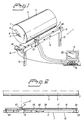
- Figures 1 and 2 show schematically in perspective parts of the measuring device 1 according to the invention for measuring without contact in a predetermined measuring area 2 at, on, around and along an envelope surface 3 of at least one measuring object 5 rotatably journalled in a machine stand 4, preferably the machine stand 4 of a paper machine, to determine the cylindricity and/or straightness of said object, as well as any other desired property or determination of or at said measuring object 5, such as corrosion, wear, temperature or velocity, and also suitable properties of a material web running over and around said measuring object 5 deemed advantageous to determine with the aid of said measuring device 1 comprising at least one measuring means 6 suitable for the purpose.
- the measuring object 5 comprises a substantially cylindrical body, e.g. a roll or a cylinder, rotating about an axis of rotation 8, such as a drive shaft.
- At least one suitable revolution pulse device 9 is arranged close to the measuring object 5, suitably at one end wall 7 or one drive shaft extension 8 so that it can be determined when the measuring object 5 is at its zero or starting position, when it has rotated part of a revolution, one complete revolution or several complete revolutions.
- said revolution pulse device 9 may comprise an inductive transducer, suitably placed a few millimetres from said end wall 7, which reacts to a metal object arranged on the end wall, the transducer then having the advantage of an extremely short reaction time, a photocell detector comprising a reflector arranged at the axis of rotation 8 of the measuring object 5 and a transmitter which may be placed at a relatively much greater distance, approximately 0.5-1.0 m, from the rotating body 5 than the inductive transducer.
- the transmitter is therefore comparatively better protected than said inductive transducer but the reaction time of the photocell detector is somewhat longer than that of said inductive transducer.
- the measuring device 1 also comprises a measuring stand 10 consisting of an elongate, rigid, i.e. form-stable, support member 11 arranged substantially parallel with the axis of rotation 8 of the measuring object 5, e.g. a linear unit or a measuring beam, at each end of which measuring beam 11 an attachment means 12 is arranged.
- the measuring stand 10 is also provided with a linearly movably journalled measuring carriage 13 on which the measuring means 6 is arranged and which is arranged to be moved substantially parallel with said measuring beam 11, as well as a traversing device 14 to move said measuring carriage 13 to preferably predetermined, optional positions along said measuring beam 11 where measurement is desired, and an electronic measuring and control unit 15.
- substantially parallel with the axis of rotation 8 of the measuring object 5" is meant that the support member 11 is arranged so that said measurements will always be performed within the measuring area of respective measuring means 6.
- each of said attachment means 12 may comprise at least one leg, a support or an attachment to the machine stand 4 mentioned above, in which the cylindrical body/bodies 5 to be measured are rotatably arranged, or else to some other permanent member able to give the requisite stability for the measuring device 1, e.g. the foundation of the machine.
- the measuring device 1 When using the measuring device 1 according to the invention with a Yankee cylinder 5 in a paper machine, a space is required for assembly and manipulation of the measuring carriage 13 of said measuring device 1 which is more or less accessible close to and between the Yankee cylinder 5 and the moving web.
- the normal placing of the measuring device in this specific case, not shown, is suitably between the creping doctor and the cleaning doctor.
- construction elements are used in or designed for the measuring device 1 that have or achieve considerable rigidity and/or a vibration suppressing effect.
- the measuring beam 11 comprises a member, or if necessary several substantially identical sections 18, form-stable in all directions and rigidly joined together coaxially and/or in parallel, which sections are suitably made of composite material or metal, preferably steel or aluminium sections, see Figure 9.
- sections are suitably made of composite material or metal, preferably steel or aluminium sections, see Figure 9.
- stop member is arranged at each end of said measuring beam 11, adjustable to optional positions along the beam, see Figures 1-2, suitably consisting of a part of one or more non-contact end-sensing devices comprising transducers such as photocells, inductive transducers or the like for recording the current position of said measuring carriage 13 relative a start or end position as described in more detail below.
- Said stop member 20 may consist of any other known type of position-recording means, e.g.
- Non-contact stop members 20 are preferable since they do not cause unfavourable influence in the form of impact jolts.
- One or more linear journalling means 21, such as linear bearings or guides, are arranged along the measuring beam 11, substantially parallel thereto and at one or more of its sides.
- two journalling members 21 are situated, one at the upper side 22 and the other at the lower side 23 of the measuring beam 11, which journalling members 21 comprise one or more parallel guides constituting a shaped bar, slide or rail along which some form of journalling member 24 arranged on the measuring carriage 13 runs in cooperation therewith.
- the journalling member may consist, for instance, of a number of bogie wheels, slide, ball or roller bearings.
- One or more sliding surfaces 25 of some type of self-lubricating material may be arranged between said measuring carriage 13 and measuring beam 11, suitably along the entire extension of said guides mentioned above, beside at least one or between several of these guides.
- said measuring carriage 13 comprises a positioning unit 26 on which the coupling 27 for the traversing means 14 is arranged, enabling positioning of the measuring carriage 13 in a to and fro linear movement to each desired and predetermined position along one or more of the linear journalling means 21 of the measuring beam 11, suitably along one or more of the journalling means 21 arranged at the sides of the measuring beam 11 facing the measuring object 5.
- the positioning unit 26 comprises a slide or carriage 28 in which one each of said couplings 27 for the traversing device 14 is arranged at its two opposite ends seen in the direction of travel, and also a sleeve or frame 29 surrounding the support beam 11 and connecting said carriage 28 with the other journalling means 21 described above.
- a tensioning device 30 is arranged on the measuring carriage 13, at the lower edge of the frame 29, the function of the tensioning device 30 being to suitably hold and clamp the measuring carriage 13 against the measuring beam 11 during its linear movements to and fro.
- the tensioning device 30, which in the device shown, comprises a link arm 31 arranged pivotably at one end of the frame 29, with a suitable journalling means 32 such as a bogie wheel at its free, opposite end, which tensioning device 30 is clamped against and cooperates with the support member 11, suitably one of the linear journalling means 21 described above, of the support member 11.
- Said link arm 31 can then either be fixed at a specific angle by means of a screw member 33 arranged at its pivot point, or a suitable tension force can be obtained by means of a spring member, not shown, arranged together with said link arm 31.
- the other, movable part of the above-mentioned non-contact end-sensing device(s) 20 is also fitted on the measuring carriage 13, which end-sensing devices 20 record the current position of the measuring carriage 13 in relation to its start or end position travelling along the measuring beam 11, so that the traversing movement can always commence and finish at a known position in relation to said end position.
- the measured values obtained can thus easily be compared within the same measuring sequence and also with equivalent measured values obtained during previous measurements performed on the same or other similar measuring objects 5.
- An adjustment member 35 is also arranged at the positioning unit 26 of the measuring carriage 13, see Figures 6, 8 and 9, and comprises a shaft 36 arranged in suitable manner in the longitudinal direction of the support beam 11, and at least one hinge member 37 pivotable about this shaft 36.
- Said hinge member 37 can be secured to the shaft 36, e.g. by a screw member 38, so that a retaining and adjustment member 39, e.g. consisting of a platform of bent sheet metal, arranged at this hinge member(s) 37, on which platform 39 the measuring means 6 is/are mounted, can be set at a desired angle to the envelope surface 3 of the measuring object 5.
- a manual or automatic adjustment member 40 is arranged, in the embodiment illustrated in Figure 9, at the lower side of said platform 39.
- the adjustment member 40 then comprises a spring member 41, which in the embodiment illustrated consists of a rod 42 attached to the hinge member 37 perpendicularly to the measuring object 5 and parallel with said platform 39 and a forward control element 43 and a rear control element 44, both displaceable along the rod 42, which control elements 43, 44 are permanently mounted on the platform 39, the latter thus being adjustable along said rod 42, and also a spring 45 coiled around said rod 42 so that a force is obtained on the platform 39 directed against the measuring object 5, and also a manual or automatic actuator 46, in the embodiment shown in Figure 6 extending between said hinge 37 and the rear control element 44 and acting parallel to this spring member 41, e.g. consisting of a micrometer screw or an electric motor, so that said distance from the envelope surface 3 of the measuring object 5 can be controlled,
- a manual or automatic actuator 46 in the embodiment shown in Figure 6 extending between said hinge 37 and the rear control
- One or more protective spacers 47 are fitted on the front of the platform 39, facing the measuring object 5, suitably shaped as blocks of plastic, ceramic, composite or some other suitable material that does not damage the envelope surface 3 of said measuring object 5 in the event of contact between them, during adjustment of said platform 39, for instance.
- Said traversing device 14 comprises a motor 48, see Figure 5, such as a stepping or servo motor, suitably arranged at one end of the measuring beam 11 for propelling said measuring carriage 13, a coupling 49 which may comprise a planetary gear, a drive shaft 50 from the motor 48 connected to one wheel, in this case constituting a driving wheel, of at least two journalling members such as wheels 51, 52, between and around which wheels 51, 52 at least one synchronous transmission belt 53 runs in a loop in a completely or partially sheltered position inside the support member 11, and each of the above-mentioned coupling 27 between the ends of the transmission belt 53 and the positioning unit 26 of said measuring carriage 13.
- Said coupling 27 is suitably designed with some form of means to regulate the tension in the transmission belt 53.
- the described motor 48 with all movable parts carefully enclosed to protect them from external influence of dust, fluff, etc., is controlled so that it automatically adjusts the measuring carriage 13 with the aid of the transmission belt 53 to any desired position along the measuring beam 11, instead of the previous complicated and in some cases dangerous method of pushing the measuring carriage 13 manually.
- the electronic measuring and control unit 15 used in the measuring device 1 for controlling said motor 48, collecting the measured values obtained by the measuring means 6 and presenting the calculated results comprises a computer 54 with a pre-programmed measurement collection card suitably in the form of an insert card for the computer.
- the computer 54 is specially designed for recording measurement data from different forms and types of transducers, including the requisite data processing of said measured values, and suitably presents the result either visually on a display screen 55 or in the form of a data print-out.
- the computer 54 may also include a calibrating unit for the straightness reference 16.
- the straightness reference 16 comprises a laser beam 58 generated by at least one laser unit comprising a laser transmitter 56 and a receiver detector 57, see Figure 2, said laser unit also including a correction and control device, not shown, enabling adjustment of the direction of the laser beam 58 to be performed with the aid of two differential micrometer screws. This fine adjustment allows an accuracy of adjustment of 0.001 mm per meter.
- the laser detector 57 comprises a 2-axis, position-sensitive receiver with a detector surface of 20x20 mm, said receiver having a display box with two display windows showing the x and y values, respectively, of the detector 57 in digital form with a resolution of 0.01 mm.
- an elongate protective device 17, mentioned above, is arranged below at least a part of the length of the laser beam 58 substantially parallel with the measuring beam 11.
- this protective device 17, which may be telescopic, comprises a laser path 59 constituting some form of an extended member 60 inside which, or sheltered by which, the laser beam 58 extends, such as a screen, hollow beam, pipe or boom at least partially surrounding or in some other way protecting the laser beam 58.
- the protective device may comprise a resilient bellows, suitably of plastic or rubber, which laser path 59 thus forms an undisturbed light channel for the laser beam 58 between its transmitter 56 and receiver 57, said extended member 60 having at least one gap, sector or groove, not shown, running horizontally along one side and extending at least along the part(s) of the member 60 located between the end positions applicable for traversing of the measuring carriage 13, said gap suitably being screened from the outer of two or more coaxial brush members arranged preferably parallel to each other on each side of said gap thereby forming a soft, flexible curtain which screens and closes the gap in a plastic and yielding manner.
- the purpose and function of said brush members is to protect the straightness reference 16 arranged in the shelter of, or inside the protective device 17, the elongate protective device 17 thus forming a space constituting said light channel in the centre of which the detector 57 or laser transmitter 56 are arranged or operate.
- Either the laser transmitter 56 or the receiver detector 57 is mounted on the measuring carriage 13 and the remaining either receiver detector 57 or laser transmitter 56 is mounted on the measuring beam 11, protected from external influence, after having been accurately adjusted with the aid of said correcting and control devices.
- the differences are thus measured in the distance between the envelope surface 3 of the measuring object 5 and the measuring means 6, the measuring means 6 being maintained in one and the same stationary position on the measuring beam 11 throughout a complete rotation of the measuring object 5.
- Measuring is suitably performed in such a way that a measured value is obtained both for each degree of rotation during a revolution so that the mentioned non-cylindricity can be obtained, and also for a number of positions along the measuring beam 11 where the location of the measuring means 6 in relation to the straightness reference 16 is determined, so that the straightness profile of the measuring object 5 can also be obtained.
- the number of measuring positions is determined by the length of the measuring object 5 and the required accuracy of the measuring result.
- the measuring results thus automatically collected, analyzed and suitably processed may be reported both in real time, in the embodiment shown on said display screen 55 included in the control and measuring unit 15, graphically in the isometric form described above for instance, or in tabular form, and also on a unit, e.g. a printer, connected thereto. If appropriate, said measurement and reporting may be performed for different operating conditions such as web speed, temperature or some other parameter of significance to operation.
- the measuring device 1 is dismountable and can therefore be packed up and simply moved when necessary between different measuring objects 5 or machines, and installed at the measuring object 5 selected, e.g. a Yankee cylinder, where said measurement can be performed during manufacture, in connection with service and repair or even during operation of the finished and installed cylindrical body 5.
- the measuring device 1 Since sufficient and relatively accessible space for mounting and handling the measuring device 1 and measuring carriage 13 is required close to and between the Yankee cylinder and the web draw, the measuring device 1 is normally placed between the creping and cleaning doctors. If necessary it is also possible to measure through the web and a position both before and after the pickup doctor may therefore be used.
- All transducers or similar measuring means used in the measuring device 1 are suitably non-contacting transducers, e.g. optical, photo-electric or inductive eddy-current transducers of known type, but may of course be entirely or partially replaced with electric, mechanical or pneumatic contact means if deemed sufficient.
- non-contacting transducers e.g. optical, photo-electric or inductive eddy-current transducers of known type, but may of course be entirely or partially replaced with electric, mechanical or pneumatic contact means if deemed sufficient.
- revolution pulse device 9 is placed on the axis of rotation 8 of the measuring object 5, in this case suitably said photocell detector, it can suitably be attached to said shaft 8 by means of a belt-like attachment member to facilitate mounting and dismantling of said revolution pulse device 9.
- the measurement of the cylindricity and/or straightness of a measuring object 5 can of course also include simultaneous recording of any other required parameter possible and desirable for measuring objects 5 of this type, using one of the measuring devices now commercially available.
- Such parameters are mentioned above and include deposits, corrosion, wear patterns, magnitude of wear, etc.
- the described invention is particularly suitable for measuring at a Yankee cylinder.
Landscapes
- Physics & Mathematics (AREA)
- General Physics & Mathematics (AREA)
- Length Measuring Devices By Optical Means (AREA)
- Length Measuring Devices With Unspecified Measuring Means (AREA)
Abstract
Description
Claims (24)
- A method for, without contact and with the aid of a measuring device (1), measuring in a predetermined measuring area (2) in connection to an envelope surface (3) of at least one measuring object (5) journalled rotatably in a machine stand of a paper machine, with respect to its cylindricity and/or its straightness relative to a straightness reference (16) arranged substantially parallel with the axis of rotation (8) of the measuring object (5), which measuring device (1) comprises said straightness reference (16), a measuring stand (10) and a linearly movably journalled measuring carriage (13) on which at least one measuring means (6) is arranged, said measuring carriage (13) during said measurement travels along an elongate form-stable support member (11) forming a part of the measuring stand (10), and running substantially parallel to the axis of rotation (8) of the measuring object (5), whereby said measuring means (6) is moved to one or more desired positions for the measurement and the measuring means (6) is caused to perform a measurement of the present measurement values at each such position selected in said measuring area (2), wherein the measuring commences with a starting position for the measuring means (6) relative the straightness reference (16) and the measuring object (5) being determined, which starting position comprises an initial position for the rotating measuring object (5), a current position along the support member (11) and a position in radial direction from the envelope surface (3) of the measuring object (5), wherein a first measurement is performed for this starting position, wherein the measuring means (6) is thereafter moved to at least one more position along the support member (11) while this or these new positions are continuously determined in relation to each other or said starting position, whereupon a measurement occurs in said measuring area (2) at each position, and wherein a laser beam (58) is used as straightness reference (16), said laser beam being generated by a laser unit, characterised in that the laser beam (58) is protected from external influence by being arranged along at least a part of its length in the shelter of an elongate protective device (17) arranged substantially parallel with said support member (11).
- A method as claimed in claim 1, characterized in that at least one revolution pulse device (9) is arranged at the measuring object (5), that said initial position is determined with the aid of the revolution pulse device (9), and that said current position along the support member (11) is determined with the aid of stop members (20) arranged at each end of the support member (11).
- A method as claimed in claim 1 or claim 2, characterized in that the laser beam (58) is protected from external influence by the laser unit and the laser beam (58) generated thereby being arranged inside the elongate protective device (17) arranged parallel with said support member (11).
- A method as claimed in any of the preceding claims, characterized in that the measured values obtained are processed and reported by means of an electronic measuring and control unit (15).
- A method as claimed in claim 4, characterized in that traversing of the measuring carriage (13) along the support member (11) occurs automatically with the aid of a traversing device (14) comprising a motor (48), a coupling (49), a drive shaft (50), at least two wheels (51, 52), one of which comprises a driving wheel (51), between and around which wheels (51, 52) at least one synchronous transmission belt (53) runs in a loop secured to said measuring carriage (13), the synchronous transmission belt (53) being located in a completely or partially sheltered position inside the support member (11), and that the traversing device (14) is controlled by the electronic measuring and control unit (15) which has been pre-programmed to place the measuring carriage (13) in optional, predetermined positions along the support member (11).
- A method as claimed in one or more of the preceding claims, characterized in that a retaining and adjustment member (39) arranged on said measuring carriage (13) is set at a desired angle relative the envelope surface (3) of the measuring object (5) with the aid of an adjustment member (35) arranged at a positioning unit (26) arranged on the measuring carriage (13) and comprising a shaft (36) arranged in the longitudinal direction of the support member (11), that at least one hinge member (37) is turned about this shaft (36), and that the hinge member (37) is thereafter secured to the shaft (36) so that the retaining and adjustment member (39) arranged at these hinge members (37) acquires said desired angle to the envelope surface (3) of the measuring object (5).
- A method as claimed in claim 6, characterized in that said retaining and adjustment member (39) is also set in radial direction at a distance from the envelope surface (3) of the measuring object (5) suitable for said measuring means (6), with the aid of a manual or automatic adjustment device (40), thereby enabling said distance to be regulated at the automatic adjustment device (40) with the aid of the measuring and control unit (15).
- A method as claimed in any of the preceding claims, characterized in that measurement occurs in the predetermined measuring area (2) of every other desired property or parameter of or at said measuring object (5), and also of a material web running over and around said measuring object (5) which it is considered advantageous to determine with the aid of said measuring device (1), such as corrosion, wear, temperature or velocity, and that at least one additional suitable measuring means (6) is therefore arranged on the measuring device (1).
- A measuring device (1) for, without contact, measuring in a predetermined measuring area (2) in connection to an envelope surface (3) of at least one measuring object (5) journalled rotatably in a machine stand of a paper machine, with respect to its cylindricity and/or its straightness relative to a straightness reference (16), said straightness reference (16) being arranged substantially parallel with the axis of rotation (8) of the measuring object (5), which measuring device (1) comprises said straightness reference (16), a measuring stand (10) and a linearly movably journalled measuring carriage (13) on which at least one measuring means (6) is arranged, said measuring carriage (13) during said measurement is traversed along an elongate form-stable support member (11) forming a part of the measuring stand (10), and running substantially parallel to the axis of rotation (8) of the measuring object (5), wherein said straightness reference (16) comprises a laser beam (58) which is generated by a laser unit comprising a laser transmitter (56) and a receiver detector (57), characterised in that said laser beam (58) is protected from external influence by being arranged along at least a part of its length in the shelter of an elongate protective device (17) arranged substantially parallel with said support member (11).
- A measuring device as claimed in claim 9, characterized in that the laser unit and thus its laser transmitter (56) and receiver detector (57) are arranged inside the elongate protective device (17) arranged substantially parallel to said support member (11).
- A measuring device as claimed in claim 9 or claim 10, characterized in that the measuring device (1) also includes an electronic measuring and control unit (15).
- A measuring device as claimed in any of claims 9 to 11, characterized in that the measuring device (1) also includes an automatic traversing device (14) to set said measuring carriage (13) in desired measuring positions along said support member (11), said traversing device (14) comprising a motor (48) suitably arranged at one end of the support member (11) and comprising a coupling (49) and a drive shaft (50) connected to one of at least two wheels (51, 52) provided as journalling members, one of which comprises a driving wheel (51), between and around which wheels (51, 52) at least one synchronous transmission belt (53) runs in a loop in a completely or partially sheltered position inside the support member (11), and each one a coupling (27) between the ends of each transmission belt (53) and a positioning unit (26) arranged at the measuring carriage (13).
- A measuring device as claimed in any of claims 9 to 12, characterized in that said support member (11) comprises one or more form-stable, substantially identical sections (18) joined together by means of suitable joints (19) to form a coherent length corresponding to at least the length of the desired measuring area (2), which joints (19) are recessed in the sides of the sections (18), a stop member (20) arranged at each end of said support member (11), suitably consisting of one part of one or more contact-free end-sensing devices comprising transducers such as photocells, inductive transducers or the like for recording the current position of said measuring carriage (13) relative a start or end position along the support member (11), one or more linear journalling means (21) arranged substantially parallel with and close to one or more of the sides of the support member (11), which linear journalling means (21) comprise one or more parallel guides constituting a shaped bar, slide or rail along which some form of journalling member (24) arranged on the measuring carriage (13) runs in cooperation.
- A measuring device as claimed in claim 13 in combination with claim 12, characterized in that the positioning unit (26) comprises a slide or carriage (28) in which one each of said couplings (27) for the traversing means (14) is arranged at its two opposite ends seen in the direction of travel, and also a sleeve or frame (29) surrounding the support member (11) and connecting said carriage (28) with the linear journalling means (21).
- A measuring device as claimed in claim 13 or 14, characterized in that a tensioning device (30) is arranged at the measuring carriage (13), said tensioning device comprising a link arm (31) arranged pivotably at one end of the measuring carriage (13), with a journalling means (32) at its free, opposite end, which tensioning device (30) is clamped against and cooperates with the support member (11), suitably one of the linear journalling means (21) of the support member (11).
- A measuring device as claimed in claim 12, or in claim 13 in combination with claim 12, or in claim 14, characterized in that an adjustment member (35) is also arranged at the positioning unit (26) of the measuring carriage (13), which adjustment member comprises a shaft (36) arranged in the longitudinal direction of the support member (11) and at least one hinge member (37) pivotable about this shaft (36), which can be secured to the shaft (36) so that a retaining and adjustment member (39) arranged at this or these hinge member(s) (37), on which member (39) said measuring means (6) is/are mounted, can be set at a desired angle to the envelope surface (3) of the measuring object (5).
- A measuring device as claimed in claim 16, characterized in that a manual or automatic adjustment member (40) is arranged at said retaining and adjustment member (39) to adjust this also in radial direction to a suitable distance for said measuring means (6) from said envelope surface (3), which adjustment member (40) comprises a spring member (41) so that a force is obtained directed on the retaining and adjustment member (39) and against the measuring object (5), and also a manual or automatic actuator (46) acting parallel to this spring member (41), so that said distance from the envelope surface (3) of the measuring object (5) can be controlled, in the latter case automatically, by the measuring and control unit (15) in cooperation with said spring member (41).
- A measuring device as claimed in claims 16 and 17, characterized in that one or more protective spacers (47) are fitted on the front of the retaining and adjustment member (39), facing the measuring object (5), suitably shaped as blocks of plastic, ceramic, composite or some other suitable material that does not damage the envelope surface (3) of said measuring object (5) in the event of contact between them.
- A measuring device as claimed in any of claims 16 to 18, characterized in that the retaining and adjustment member (39) comprises a platform of bent sheet metal.
- A measuring device as claimed in any of claims 9 to 19, characterized in that an elongate protective device (17) is arranged below at least a part of the length of the laser beam (58), substantially parallel with the support member (11), which protective device (17) comprises a laser path (59) comprising some form of elongate member (60) within which, or in the shelter of which, the laser beam (58) extends, which laser path (59) thus forms a light channel for the laser beam (58) between its transmitter (56) and its receiver (57), which elongate member (60) comprises at least one gap, sector or track running horizontally and extending at least along the part(s) of the elongate member (60) situated between the end positions applicable to the traversing of the measuring carriage (13), in which light channel the detector (57) and the laser transmitter (56) are arranged or operate, of which either the laser transmitter (56) or the receiver detector (57) is mounted on the measuring carriage (13) and the remaining either receiver detector (57) or laser transmitter (56) is mounted on the support member (11).
- A measuring device as claimed in claim 20, characterized in that the protective device (17) is telescopic.
- A measuring device as claimed in claim 20 or 21, characterized in that the elongate member (60) comprises a screen, hollow beam or pipe, or even resilient bellows, for instance, the bellows then suitably being of plastic or rubber, said member at least partially surrounding or otherwise protecting the laser beam (58).
- A measuring device as claimed in any of claims 20 to 22, characterized in that the gap is screened from the outer of two or more coaxial brush members.
- A measuring device as claimed in any of claims 9 to 23, characterized in that the measuring device (1) can be removed and transported between different measuring objects (5) or machines and thus installed at a measuring object (5) selected on a particular occasion so that measuring can be performed during manufacture of the measuring object (5), and also during operation of the finished and installed object.
Applications Claiming Priority (3)
| Application Number | Priority Date | Filing Date | Title |
|---|---|---|---|
| SE9702945 | 1997-08-22 | ||
| SE9702945A SE510988C2 (en) | 1997-08-22 | 1997-08-22 | Method and measuring device to measure the straightness of a casing surface without contact |
| PCT/SE1998/001465 WO1999010708A1 (en) | 1997-08-22 | 1998-08-13 | Method and measuring device for measuring at an envelope surface |
Publications (2)
| Publication Number | Publication Date |
|---|---|
| EP1007904A1 EP1007904A1 (en) | 2000-06-14 |
| EP1007904B1 true EP1007904B1 (en) | 2005-03-09 |
Family
ID=20407937
Family Applications (1)
| Application Number | Title | Priority Date | Filing Date |
|---|---|---|---|
| EP98939039A Expired - Lifetime EP1007904B1 (en) | 1997-08-22 | 1998-08-13 | Method and device for measuring an envelope surface |
Country Status (5)
| Country | Link |
|---|---|
| EP (1) | EP1007904B1 (en) |
| AT (1) | ATE290684T1 (en) |
| DE (1) | DE69829295T2 (en) |
| SE (1) | SE510988C2 (en) |
| WO (1) | WO1999010708A1 (en) |
Cited By (2)
| Publication number | Priority date | Publication date | Assignee | Title |
|---|---|---|---|---|
| CN102628674A (en) * | 2012-03-30 | 2012-08-08 | 苏州筑邦测控科技有限公司 | Non-contact test piece surface testing system |
| CN104330060A (en) * | 2014-10-29 | 2015-02-04 | 中铁建电气化局集团康远新材料有限公司 | Portable straightness detection device |
Families Citing this family (10)
| Publication number | Priority date | Publication date | Assignee | Title |
|---|---|---|---|---|
| AT502875B1 (en) * | 2002-12-11 | 2007-10-15 | Andritz Ag Maschf | METHOD AND DEVICE FOR DETERMINING SURFACE PARAMETERS OF ROTATING CYLINDERS |
| FI20105205A0 (en) * | 2010-03-03 | 2010-03-03 | Pyynikki Engineering Oy | PROCEDURES AND ARRANGEMENTS FOR DEFINING THE ROLLER PROFILE AND / OR FOR CHECKING GRINDING |
| FR3001032B1 (en) | 2013-01-17 | 2015-03-13 | Snecma | DEVICE FOR MEASURING THE INTERNAL PROFILE OF A HOLLOW TREE |
| CN106352813A (en) * | 2016-10-10 | 2017-01-25 | 江苏理工学院 | Sensing-technology-based shaft workpiece measurement device and measurement method thereof |
| CN108534679B (en) * | 2018-05-14 | 2019-08-13 | 西安电子科技大学 | A kind of cylindrical member axis pose without target self-operated measuring unit and method |
| CN108844445B (en) * | 2018-09-06 | 2020-03-20 | 丹阳市亚邦精密机械有限公司 | Coaxiality detection tool for transmission shaft |
| EP4000931B1 (en) | 2019-05-09 | 2023-06-14 | Heidelberger Druckmaschinen AG | Device for measuring elevations of the surface of a rotating body |
| CN111397533A (en) * | 2020-04-08 | 2020-07-10 | 河北新兴铸管有限公司 | Pipe fitting ovality detection device and detection method |
| DE102021125071A1 (en) * | 2020-10-22 | 2022-04-28 | Heidelberger Druckmaschinen Aktiengesellschaft | Device for measuring elevations on the surface of a rotating body |
| CN113405454B (en) * | 2021-05-14 | 2023-05-16 | 上海交大智邦科技有限公司 | Device, method and software system suitable for attitude measurement of cabin product |
Citations (1)
| Publication number | Priority date | Publication date | Assignee | Title |
|---|---|---|---|---|
| US5617645A (en) * | 1995-05-02 | 1997-04-08 | William R. W. Wick | Non-contact precision measurement system |
Family Cites Families (4)
| Publication number | Priority date | Publication date | Assignee | Title |
|---|---|---|---|---|
| US3923402A (en) * | 1973-01-10 | 1975-12-02 | Beloit Corp | Method and apparatus for aligning paper machinery |
| DE3419059A1 (en) * | 1984-05-22 | 1985-11-28 | Prüftechnik KG Dieter Busch + Partner GmbH & Co, 8045 Ismaning | DEVICE FOR DETECTING CHANGES IN THE MUTUAL POSITION OF SPECIAL ASSEMBLED MACHINES |
| ATE150365T1 (en) * | 1994-04-26 | 1997-04-15 | Schablonentechnik Kufstein Ag | METHOD AND DEVICE FOR PRODUCING A SCREEN PRINTING STENCIL |
| US5587051A (en) * | 1994-07-29 | 1996-12-24 | Ostermayer; Volker | Simplified laser apparatus and method for measuring stock thickness on papermaking machines |
-
1997
- 1997-08-22 SE SE9702945A patent/SE510988C2/en not_active IP Right Cessation
-
1998
- 1998-08-13 DE DE69829295T patent/DE69829295T2/en not_active Expired - Lifetime
- 1998-08-13 AT AT98939039T patent/ATE290684T1/en active
- 1998-08-13 WO PCT/SE1998/001465 patent/WO1999010708A1/en active IP Right Grant
- 1998-08-13 EP EP98939039A patent/EP1007904B1/en not_active Expired - Lifetime
Patent Citations (1)
| Publication number | Priority date | Publication date | Assignee | Title |
|---|---|---|---|---|
| US5617645A (en) * | 1995-05-02 | 1997-04-08 | William R. W. Wick | Non-contact precision measurement system |
Cited By (2)
| Publication number | Priority date | Publication date | Assignee | Title |
|---|---|---|---|---|
| CN102628674A (en) * | 2012-03-30 | 2012-08-08 | 苏州筑邦测控科技有限公司 | Non-contact test piece surface testing system |
| CN104330060A (en) * | 2014-10-29 | 2015-02-04 | 中铁建电气化局集团康远新材料有限公司 | Portable straightness detection device |
Also Published As
| Publication number | Publication date |
|---|---|
| SE510988C2 (en) | 1999-07-19 |
| WO1999010708A1 (en) | 1999-03-04 |
| DE69829295D1 (en) | 2005-04-14 |
| DE69829295T2 (en) | 2006-04-13 |
| SE9702945D0 (en) | 1997-08-15 |
| SE9702945L (en) | 1999-02-23 |
| EP1007904A1 (en) | 2000-06-14 |
| ATE290684T1 (en) | 2005-03-15 |
Similar Documents
| Publication | Publication Date | Title |
|---|---|---|
| US6169290B1 (en) | Method and measuring device for measuring at an envelope surface | |
| EP1007904B1 (en) | Method and device for measuring an envelope surface | |
| US6327788B1 (en) | Surface form measurement | |
| FI100708B (en) | Machine for checking an overhead line | |
| US4548105A (en) | Method and arrangement for observing a position | |
| CA1116843A (en) | Precision measuring device for cylindrical objects | |
| EP0238137B1 (en) | Independent measuring apparatus for grinder machines for cylinders and the like having members for structural and superficial control | |
| PT2247396E (en) | Method to check and control a roller bending machine for continuously bending an elongated workpiece at variable curvature radii, and machine so controlled | |
| WO2011107660A1 (en) | Method and arrangement for determining the profile of a roll surface and for controlling grinding | |
| US5226577A (en) | Web guide for elongated flexible web | |
| GB2039673A (en) | Precision length measuring arrangement | |
| US7472490B2 (en) | Shape-measuring assembly for a grinding machine | |
| CN101137887B (en) | Shape-measuring assembly for a grinding machine | |
| JP2837219B2 (en) | Method and apparatus for measuring roll profile | |
| US5317913A (en) | Apparatus for determining the sag of a running web of material transversely to its longitudinal direction | |
| JPH0365841B2 (en) | ||
| GB2259052A (en) | Compensating for lack of roundness in printing cylinders. | |
| KR100628350B1 (en) | Scan type apparatus for measuring wheel and measuring system using the same | |
| US5379497A (en) | Apparatus for inspecting settings on a textile fabric shearing machine | |
| JPH08152318A (en) | Inner diameter measuring apparatus | |
| FI57708C (en) | PRECISIONSMAETANORDNING FOER CYLINDRISKA FOEREMAOL | |
| CN211179642U (en) | Auxiliary detection device of handheld eddy current flaw detector | |
| FI100094B (en) | Procedure and plant for machine tool control | |
| RU2279631C2 (en) | Method of measuring of the arbors misalignment | |
| US2844876A (en) | Measuring machine |
Legal Events
| Date | Code | Title | Description |
|---|---|---|---|
| PUAI | Public reference made under article 153(3) epc to a published international application that has entered the european phase |
Free format text: ORIGINAL CODE: 0009012 |
|
| 17P | Request for examination filed |
Effective date: 20000204 |
|
| AK | Designated contracting states |
Kind code of ref document: A1 Designated state(s): AT DE GB |
|
| RIN1 | Information on inventor provided before grant (corrected) |
Inventor name: STARK, MATS, OLA Inventor name: ROSBERG, LARS, TOMAS, RAGNAR |
|
| RAP1 | Party data changed (applicant data changed or rights of an application transferred) |
Owner name: METSO PAPER KARLSTAD AKTIEBOLAG |
|
| RTI1 | Title (correction) |
Free format text: METHOD AND DEVICE FOR MEASURING AN ENVELOPE SURFACE |
|
| GRAP | Despatch of communication of intention to grant a patent |
Free format text: ORIGINAL CODE: EPIDOSNIGR1 |
|
| RAP1 | Party data changed (applicant data changed or rights of an application transferred) |
Owner name: METSO PAPER, INC. |
|
| GRAS | Grant fee paid |
Free format text: ORIGINAL CODE: EPIDOSNIGR3 |
|
| GRAA | (expected) grant |
Free format text: ORIGINAL CODE: 0009210 |
|
| AK | Designated contracting states |
Kind code of ref document: B1 Designated state(s): AT DE GB |
|
| REG | Reference to a national code |
Ref country code: GB Ref legal event code: FG4D |
|
| REF | Corresponds to: |
Ref document number: 69829295 Country of ref document: DE Date of ref document: 20050414 Kind code of ref document: P |
|
| PLBE | No opposition filed within time limit |
Free format text: ORIGINAL CODE: 0009261 |
|
| STAA | Information on the status of an ep patent application or granted ep patent |
Free format text: STATUS: NO OPPOSITION FILED WITHIN TIME LIMIT |
|
| 26N | No opposition filed |
Effective date: 20051212 |
|
| PGFP | Annual fee paid to national office [announced via postgrant information from national office to epo] |
Ref country code: GB Payment date: 20090827 Year of fee payment: 12 |
|
| PGFP | Annual fee paid to national office [announced via postgrant information from national office to epo] |
Ref country code: DE Payment date: 20100823 Year of fee payment: 13 Ref country code: AT Payment date: 20100812 Year of fee payment: 13 |
|
| GBPC | Gb: european patent ceased through non-payment of renewal fee |
Effective date: 20100813 |
|
| PG25 | Lapsed in a contracting state [announced via postgrant information from national office to epo] |
Ref country code: GB Free format text: LAPSE BECAUSE OF NON-PAYMENT OF DUE FEES Effective date: 20100813 |
|
| REG | Reference to a national code |
Ref country code: DE Ref legal event code: R119 Ref document number: 69829295 Country of ref document: DE Effective date: 20120301 |
|
| REG | Reference to a national code |
Ref country code: AT Ref legal event code: MM01 Ref document number: 290684 Country of ref document: AT Kind code of ref document: T Effective date: 20110813 |
|
| PG25 | Lapsed in a contracting state [announced via postgrant information from national office to epo] |
Ref country code: AT Free format text: LAPSE BECAUSE OF NON-PAYMENT OF DUE FEES Effective date: 20110813 |
|
| PG25 | Lapsed in a contracting state [announced via postgrant information from national office to epo] |
Ref country code: DE Free format text: LAPSE BECAUSE OF NON-PAYMENT OF DUE FEES Effective date: 20120301 |