EP1007833B1 - Procede de realisation de l'allumage dans un moteur a gaz a pistons alternatifs multicylindre par injection d'un gaz d'allumage - Google Patents
Procede de realisation de l'allumage dans un moteur a gaz a pistons alternatifs multicylindre par injection d'un gaz d'allumage Download PDFInfo
- Publication number
- EP1007833B1 EP1007833B1 EP99927836A EP99927836A EP1007833B1 EP 1007833 B1 EP1007833 B1 EP 1007833B1 EP 99927836 A EP99927836 A EP 99927836A EP 99927836 A EP99927836 A EP 99927836A EP 1007833 B1 EP1007833 B1 EP 1007833B1
- Authority
- EP
- European Patent Office
- Prior art keywords
- gas
- ignition
- pressure
- cylinder
- combustion
- Prior art date
- Legal status (The legal status is an assumption and is not a legal conclusion. Google has not performed a legal analysis and makes no representation as to the accuracy of the status listed.)
- Expired - Lifetime
Links
Images


Classifications
-
- F—MECHANICAL ENGINEERING; LIGHTING; HEATING; WEAPONS; BLASTING
- F02—COMBUSTION ENGINES; HOT-GAS OR COMBUSTION-PRODUCT ENGINE PLANTS
- F02D—CONTROLLING COMBUSTION ENGINES
- F02D41/00—Electrical control of supply of combustible mixture or its constituents
- F02D41/30—Controlling fuel injection
- F02D41/38—Controlling fuel injection of the high pressure type
- F02D41/40—Controlling fuel injection of the high pressure type with means for controlling injection timing or duration
- F02D41/402—Multiple injections
- F02D41/403—Multiple injections with pilot injections
-
- F—MECHANICAL ENGINEERING; LIGHTING; HEATING; WEAPONS; BLASTING
- F02—COMBUSTION ENGINES; HOT-GAS OR COMBUSTION-PRODUCT ENGINE PLANTS
- F02D—CONTROLLING COMBUSTION ENGINES
- F02D19/00—Controlling engines characterised by their use of non-liquid fuels, pluralities of fuels, or non-fuel substances added to the combustible mixtures
- F02D19/02—Controlling engines characterised by their use of non-liquid fuels, pluralities of fuels, or non-fuel substances added to the combustible mixtures peculiar to engines working with gaseous fuels
- F02D19/021—Control of components of the fuel supply system
- F02D19/023—Control of components of the fuel supply system to adjust the fuel mass or volume flow
- F02D19/024—Control of components of the fuel supply system to adjust the fuel mass or volume flow by controlling fuel injectors
-
- F—MECHANICAL ENGINEERING; LIGHTING; HEATING; WEAPONS; BLASTING
- F02—COMBUSTION ENGINES; HOT-GAS OR COMBUSTION-PRODUCT ENGINE PLANTS
- F02D—CONTROLLING COMBUSTION ENGINES
- F02D41/00—Electrical control of supply of combustible mixture or its constituents
- F02D41/30—Controlling fuel injection
- F02D41/38—Controlling fuel injection of the high pressure type
- F02D41/3809—Common rail control systems
- F02D41/3836—Controlling the fuel pressure
-
- F—MECHANICAL ENGINEERING; LIGHTING; HEATING; WEAPONS; BLASTING
- F02—COMBUSTION ENGINES; HOT-GAS OR COMBUSTION-PRODUCT ENGINE PLANTS
- F02M—SUPPLYING COMBUSTION ENGINES IN GENERAL WITH COMBUSTIBLE MIXTURES OR CONSTITUENTS THEREOF
- F02M21/00—Apparatus for supplying engines with non-liquid fuels, e.g. gaseous fuels stored in liquid form
- F02M21/02—Apparatus for supplying engines with non-liquid fuels, e.g. gaseous fuels stored in liquid form for gaseous fuels
- F02M21/0218—Details on the gaseous fuel supply system, e.g. tanks, valves, pipes, pumps, rails, injectors or mixers
- F02M21/0248—Injectors
- F02M21/0275—Injectors for in-cylinder direct injection, e.g. injector combined with spark plug
-
- F—MECHANICAL ENGINEERING; LIGHTING; HEATING; WEAPONS; BLASTING
- F02—COMBUSTION ENGINES; HOT-GAS OR COMBUSTION-PRODUCT ENGINE PLANTS
- F02M—SUPPLYING COMBUSTION ENGINES IN GENERAL WITH COMBUSTIBLE MIXTURES OR CONSTITUENTS THEREOF
- F02M21/00—Apparatus for supplying engines with non-liquid fuels, e.g. gaseous fuels stored in liquid form
- F02M21/02—Apparatus for supplying engines with non-liquid fuels, e.g. gaseous fuels stored in liquid form for gaseous fuels
- F02M21/0218—Details on the gaseous fuel supply system, e.g. tanks, valves, pipes, pumps, rails, injectors or mixers
- F02M21/0284—Arrangement of multiple injectors or fuel-air mixers per combustion chamber
-
- F—MECHANICAL ENGINEERING; LIGHTING; HEATING; WEAPONS; BLASTING
- F02—COMBUSTION ENGINES; HOT-GAS OR COMBUSTION-PRODUCT ENGINE PLANTS
- F02B—INTERNAL-COMBUSTION PISTON ENGINES; COMBUSTION ENGINES IN GENERAL
- F02B1/00—Engines characterised by fuel-air mixture compression
- F02B1/12—Engines characterised by fuel-air mixture compression with compression ignition
-
- F—MECHANICAL ENGINEERING; LIGHTING; HEATING; WEAPONS; BLASTING
- F02—COMBUSTION ENGINES; HOT-GAS OR COMBUSTION-PRODUCT ENGINE PLANTS
- F02D—CONTROLLING COMBUSTION ENGINES
- F02D41/00—Electrical control of supply of combustible mixture or its constituents
- F02D41/0025—Controlling engines characterised by use of non-liquid fuels, pluralities of fuels, or non-fuel substances added to the combustible mixtures
-
- Y—GENERAL TAGGING OF NEW TECHNOLOGICAL DEVELOPMENTS; GENERAL TAGGING OF CROSS-SECTIONAL TECHNOLOGIES SPANNING OVER SEVERAL SECTIONS OF THE IPC; TECHNICAL SUBJECTS COVERED BY FORMER USPC CROSS-REFERENCE ART COLLECTIONS [XRACs] AND DIGESTS
- Y02—TECHNOLOGIES OR APPLICATIONS FOR MITIGATION OR ADAPTATION AGAINST CLIMATE CHANGE
- Y02T—CLIMATE CHANGE MITIGATION TECHNOLOGIES RELATED TO TRANSPORTATION
- Y02T10/00—Road transport of goods or passengers
- Y02T10/10—Internal combustion engine [ICE] based vehicles
- Y02T10/30—Use of alternative fuels, e.g. biofuels
-
- Y—GENERAL TAGGING OF NEW TECHNOLOGICAL DEVELOPMENTS; GENERAL TAGGING OF CROSS-SECTIONAL TECHNOLOGIES SPANNING OVER SEVERAL SECTIONS OF THE IPC; TECHNICAL SUBJECTS COVERED BY FORMER USPC CROSS-REFERENCE ART COLLECTIONS [XRACs] AND DIGESTS
- Y02—TECHNOLOGIES OR APPLICATIONS FOR MITIGATION OR ADAPTATION AGAINST CLIMATE CHANGE
- Y02T—CLIMATE CHANGE MITIGATION TECHNOLOGIES RELATED TO TRANSPORTATION
- Y02T10/00—Road transport of goods or passengers
- Y02T10/10—Internal combustion engine [ICE] based vehicles
- Y02T10/40—Engine management systems
Definitions
- Reciprocating gas engines that use fuel gases with high energy content can be operated using the Otto process as well as operated according to the so-called diesel gas process become. In both cases, a mixture of air and fuel gas sucked in and compressed. The ignition takes place in the Otto process by sparkover between the electrodes of one Spark plug. Ignition takes place in the diesel gas process via a so-called ignition beam, d. H. into the condensed The fuel gas-air mixture is used to initiate combustion measured amount of a self-igniting liquid Ignition fuel, usually diesel fuel, under high Pressure injected. The injected ignition fuel ignites itself and forms a large number of spaces distributed ignition sources. The by the injected ignition fuel released energy is considerably larger than that Spark energy from a spark plug. The advantages are there with regard to maintenance costs and downtimes, because with increasing ignition energy the spark plugs are high Wear rates and thus a drastically decreasing service life exhibit.
- DE-A-44 19 429 describes a method for operating a known self-igniting mixture-compressing gas engine, at an ignition gas instead of a liquid ignition fuel is used.
- the same is expediently used as the ignition gas
- Fuel gas used which is also used to operate the gas engine in Form of a fuel gas-air mixture is used.
- previously known method is everyone that forms the main combustion chamber Cylinder assigned a small prechamber into which the Ignition gas under a pressure above the compression pressure in the Main combustion chamber is located. is blown in.
- the advantage of this The procedure is that only one type of fuel must be used so that a reduction in emissions is achieved in particular with nitrogen oxides.
- the disadvantage of this method is that of using it complex engine construction due to antechambers.
- the invention has for its object an ignition method to create for gas engines that both the construction effort as well also simplifies engine operation.
- this object is achieved by an ignition method for a multi-cylinder reciprocating gas engine in which to initiate a work cycle in each to be fired Compressed, essentially contained cylinder space homogeneous, non-self-igniting mixture of fuel gas and air is ignited by blowing in a small one Amount of fuel gas as ignition gas on a hot surface, whereby the start of blowing can be specified depending on the crankshaft position is controlled by an engine control.
- the fuel gas / air mixture in the compresses each cylinder, towards the end of the compression stroke is in a homogeneous form, but as a lean mixture the auto-ignition conditions due to the mixing ratio not fulfilled.
- the small amount of fuel gas as ignition gas Pressure blown directly into the combustion chamber.
- the same fuel gas is used as the ignition gas as it is is contained in the fuel gas-air mixture, advantageously essentially without adding air.
- targeted blowing of the pilot gas is practically one in the blowing area Mixture enrichment caused by the in a narrowly limited Range the auto-ignition conditions are set.
- This hot surface can, for example in the form of an incandescent body protruding into the combustion chamber be provided with a source of supply is connected with heating energy.
- This can be, for example Be a power source through which in the starting phase of the engine maintain the required surface temperature of the filament becomes.
- the incandescent body has a sufficient temperature level on so that the power source can be turned off.
- hot surfaces can also be created by other structural designs in the cylinder space, for example by means of projections or the like.
- the control of the start of the fuel conversion takes place in each case by releasing the amount of pilot gas to be injected, so that controllability of the combustion process analogous to that Ignition timing of a spark ignition is reached.
- the ignition method according to the invention can in particular be used the use of methane-containing gases with low energy content,
- Use so-called weak gases advantageously, because over the targeted and localized self-ignition a high ignition energy is available and thus a safe ignition even with low-energy gases, but also with lean ones Fuel gas-air mixtures is guaranteed.
- Such weak gases are, for example, about coke gas, blast furnace gas or Converter gas in the steel producing industry also available as pyrolysis gas from waste incineration.
- the ignition gas with a correspondingly high pressure directly in blowing the cylinder space to be fired is in an advantageous embodiment of the invention, the ignition gas to be metered from a respective cylinder Ignition gas storage via a controllable ignition valve remove, the ignition gas storage on the one hand with a Fuel gas supply and on the other hand with a cylinder space in Connection is established and the ignition gas accumulator via a valve arrangement by working gases from the cylinder chamber with the maximum Combustion chamber pressure can be applied.
- This arrangement has the advantage that a relatively small-volume ignition gas storage with the already charged ones anyway Gas engines available pressure generation Fuel gas supply is charged at a pressure of approximately 4 to 8 bar can be. This pressure is not sufficient to Ignition gas quantity against the compression pressure in the concerned To blow cylinder space. As soon as the pilot gas storage with ignition gases is filled, the pilot gas accumulator with a straight fired cylinder connected so that the pilot gas content in Ignition gas storage by supplying a small amount of working gas from the fired cylinder room with the maximum Pressure of the work cycle is compressed.
- This work pressure surely lies above the compression pressure of the Ignition gas storage cylinder to be ignited, so that at the time of ignition for this cylinder the ignition gas with high pressure Is available and by simply opening an ignition valve can be blown into the relevant cylinder space. If you hold this valve until the charge of the concerned one Cylinder is opened, then in the pilot gas reservoir Pressure reduced so far that after closing the ignition valve the pressure of the central fuel gas supply is sufficient to fill the memory accordingly.
- the ignitability of this way with a low Amount of hot working gases from the pressure-generating cylinder space mixed ignition gases are not affected.
- the Mixing with hot working gases offers the advantage that together with the pressure increase in the pilot gas storage of the pilot gas quantity additional heat is supplied, which contributes to the cooling the relaxation of the amount of pilot gas during the injection into compensated for the cylinder space.
- pilot gas accumulator has an additional pressure accumulator is assigned, on the one hand, with the maximum combustion chamber pressure from the cylinder space assigned to the ignition gas storage is acted upon and the gas content on the other hand Ignition gas accumulator can be pressurized.
- This procedure has the advantage that the maximum working pressure the previous work cycle of the one to be sprayed Cylinders are available to compress the amount of pilot gas stands.
- the further advantage is that the pilot gas storage and the accumulator including the associated one Valves combined to form an ignition gas metering device that can be like an injector or a spark plug can be inserted into the cylinder head.
- the further advantage of this arrangement is that a Part of the valve arrangement formed from several valves that can be formed by check valves accordingly the effort involved in valves that are controlled by the engine to be controlled are reduced.
- the surface of the filament at least partially with a is provided for the fuel gas catalytically active material.
- This measure can further reduce the Ignition temperature can be caused if by an appropriate catalytic conversion of the gas forming the ignition gas the ignitability of the enriched located in the ignition area Air-fuel gas mixture is still improved.
- the energy supply to the incandescent body as a function of predeterminable Temperatures.
- predeterminable Temperatures For the different load and speed ranges ensured that there is a temperature level on the incandescent body, that is sufficient to ignite the ignition gas.
- the manner the temperature specification can depend on the use of the respective Internal combustion engine can be made dependent. It can for example, for stationary engines that are essentially continuous operation under the same load is sufficient, the energy supply to the incandescent body with a smooth running control to couple, so only indirectly the temperature of the filament capture.
- the uneven running can be recorded, among other measures with regard to the composition of the to be fed to the engine Fuel gas-air mixture at the same time Energy supply to the incandescent body can be increased, so that a reliable Ignition is reached. It is also possible to join one selected location of the combustion chamber the surface temperature to measure and if it falls below a predeterminable Target value for this combustion chamber surface temperature the incandescent body preferably in the form of electrical energy heating energy to be supplied at all or to trap to increase according to an ongoing supply of heating energy.
- Fig. 1 the method is based on a cylinder 1 Multi-cylinder reciprocating gas engine explained in more detail.
- the combustion chamber 5 is through the piston crown 2 of the top dead center located piston 3 on the one hand and through the cylinder head 4 defined.
- the cylinder head 4 can be in the usual way Be designed.
- the cylinder head 4 is with a gas inlet valve 6 and a gas outlet valve 7 provided in usual mechanical and camshaft synchronous or over fully variable valve drives by means of a motor control can be controlled according to the load specifications.
- the one Gas outlet valve 7 assigned to gas outlet channel 8 is together with the gas outlet channels not shown here remaining cylinders over an exhaust gas turbine 9, the one Turbocharger 10 drives.
- Through the turbocharger 10 is a Inlet 11 air sucked in and under appropriate Pressure increase via the inlet channels 12 of the individual cylinders fed into the combustion chamber.
- a pressure generator for example, a motorized loader 14 that Fuel gas with a pressure of, for example, 4 to 8 bar common supply line 15 to all air inlet ducts 12 or in the directly assigned to the individual cylinders Areas of the gas inlet channels 12 over one or more Valves 15.1 introduced, which are controlled by an engine control 16 become.
- An ignition gas metering device 17 is arranged on the cylinder head 4, that from the loader 14 also via a feed line 18 Fuel gas is supplied under the given pressure.
- the pilot gas metering device 17 is with a not shown here Valve arrangement provided by an engine control 16 is controllable, so that according to the work cycle via the pilot gas metering device 17 just before the upper one Dead center an amount of ignition gas contained in the combustion chamber 5 injected compressed homogeneous fuel gas-air mixture becomes.
- the pressure for the ignition gas to be injected must be above the compression pressure lie so that at the Zündgaszumeß adopted 17th the ignition gas to be blown in at a correspondingly high pressure must be available.
- the ignition gas metering device 17 is in the manner of a spark plug inserted into the cylinder head 4 and has a pin 19th in which one can be controlled with a motor control Ignition valve 20 provided blowing channel 21 is provided.
- an incandescent body 22 as a hot surface, for example in the form of an electrically heated glow pencil arranged on which the pilot gas jet strikes.
- a heater this glow plug 22 is only required as long until after the start, the surface of the glow plug is so hot that it also changes during subsequent charge changes does not cool down and has such a temperature that due to the localized reduction in the ignition temperature when blowing in the pilot gas, the quantity of pilot gas blown in defined is ignited and the compressed, as a rule lean fuel gas-air mixture in the combustion chamber 5 ignites.
- the pilot gas is blown directly into the combustion chamber the ignition process, i.e. with conventional engine designs can be used. Detached ignition rooms, Antechambers or the like are not necessary, but can also be provided.
- the glow plug 22 As via the connecting line 22.1 indicated, connected to the engine control 16.
- the connecting line 22.1 provides an electrical supply line represents the electrical energy with the glow plug is supplied for heating.
- the control or regulation also include a signal line, with the temperature level important for the ignition of the glow plug 22 detected and processed in the engine control 16 becomes.
- the engine control the glow plug 22 is initially heated, so that here the temperature is high enough and therefore reliable Ignition of the ignition gas to be injected is guaranteed is.
- the energy supply is then so long and upright to get up to the temperature conditions in the combustion chamber ensure proper ignition of the ignition beam.
- the temperature of the glow plug 22 of the Engine control are continuously monitored, so that at one Exceeding a predetermined temperature setpoint Energy supply withdrawn or completely switched off becomes. If the value falls below a specified target value or even if there is an emerging tendency for a drop in temperature can then be close to the specified target value Heating energy can be supplied again via the motor control. As a rule, a temperature of at least 600 ° C must be maintained.
- the engine control 16 can also map for the have the minimum temperature of the glow plug to be observed, which the load request, the speed but also the lambda value of the fuel gas-air mixture to be supplied to the gas engine.
- the alignment of the jet from the gas metering device 17 leaking pilot gas can relate to gas movement be made in the combustion chamber. 1 is for simplification the drawing is directed vertically against the piston crown Injection shown. However, it can be useful be inclined against the intake valve 6 align.
- the gas engine can also have several intake valves and / or have exhaust valves.
- each pilot gas metering device 17 shown in principle, which is designed that causes the compression of the ignition gases via the gas engine itself can be.
- each pilot gas metering device 17 consists essentially of one Ignition gas storage 17.1, for example via a valve 23 a check valve, connected to the fuel gas supply line 18 is.
- Each ignition gas storage 17.1 is also connected via a connecting line 24 each with the combustion chamber 5 of the other cylinder in connection, wherein in the connecting line 24 Valve 25 is arranged, for example one in the Ignition gas accumulator 17.1 opening check valve.
- This check valve 25 is set so that it opens when in the cylinder in question, for example the cylinder 1.2, the work cycle runs, so that under working pressure, as the maximum pressure, a small amount of working gas from the fired Cylinder in the ignition gas storage 17.1 of the other cylinder, for example, the cylinder 1.1 is transferred and so the amount of pilot gas contained in this memory on the the maximum pressure tapped from the other cylinder becomes.
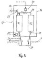
- Fig. 3 is a special embodiment for an ignition gas metering device 17 is shown.
- This consists in essentially from a housing connected to the pin 19 26, in which on the one hand an ignition gas storage 17.1 and on the other a pressure accumulator 17.2 is arranged.
- the ignition gas storage 17.1 stands, as described with reference to FIGS. 1 and 2, via a feed line 18 with the fuel gas supply 13 in Connection, being through a valve 23, for example in the form a check valve, care is taken that at a pressure increase in the ignition gas storage 17.1, no ignition gas will flow away can.
- the ignition gas storage 17.1 Via a controllable by the motor controller 16 Ignition valve 20, the ignition gas storage 17.1 can be opened so that the ignition gas via the injection duct 21 into the Combustion chamber of the relevant cylinder can get.
- a pressure channel 27 is also arranged, the the pressure accumulator 17.2 is connected and in the one Valve 28, for example a check valve, is arranged is that only with an overpressure in the combustion chamber of the concerned Cylinder opens.
- the pressure accumulator 17.2 is through with the ignition gas accumulator 17.1 a connecting line 29 connected in which also arranged by the motor controller 16 controllable valve 30 is.
- the valve 30 opened so that the higher pressure in Pressure accumulator 17.2 standing working gas in the pilot gas storage can overflow and the pressure level in the ignition gas storage 17.1 can increase accordingly, so that the pilot gas through the channel 21 pressed against the compression pressure in the combustion chamber becomes. It is useful if the pressure accumulator 17.2 has a slightly larger volume than the pilot gas storage 17.1.
Landscapes
- Engineering & Computer Science (AREA)
- Chemical & Material Sciences (AREA)
- Combustion & Propulsion (AREA)
- Mechanical Engineering (AREA)
- General Engineering & Computer Science (AREA)
- Chemical Kinetics & Catalysis (AREA)
- General Chemical & Material Sciences (AREA)
- Oil, Petroleum & Natural Gas (AREA)
- Combustion Methods Of Internal-Combustion Engines (AREA)
- Output Control And Ontrol Of Special Type Engine (AREA)
- Electrical Control Of Air Or Fuel Supplied To Internal-Combustion Engine (AREA)
Abstract
Claims (7)
- Procédé d'allumage pour un moteur à gaz à pistons alternatifs multicylindre, dans lequel, pour introduire un temps moteur, un mélange air/gaz combustible comprimé, homogène en général, non auto-inflammable et contenu dans la chambre de cylindre respectif devant être allumé est allumé par injection directe d'une faible quantité de gaz combustibles servant de gaz d'allumage sur une surface chaude, le début de l'injection étant commandé via une commande moteur de façon prédéfinie en fonction de la position du vilebrequin.
- Procédé selon la revendication 1, caractérisé en ce que le gaz d'allumage à mesurer est extrait d'un accumulateur de gaz d'allumage associé à chaque fois à un cylindre via une soupape d'allumage pouvant être commandée, laquelle est reliée d'une part à une alimentation de gaz combustible et d'autre part à la chambre de cylindre, l'accumulateur de gaz d'allumage étant alimenté par les gaz de travail sortant de la chambre de cylindre à la pression maximale de la chambre de combustion via un dispositif à soupapes.
- Procédé selon la revendication 1 ou 2, caractérisé en ce qu'un accumulateur de pression supplémentaire, qui est d'une part alimenté à la pression maximale de la chambre de combustion à partir de la chambre de cylindre associée à l'accumulateur de gaz d'allumage et dont le contenu en gaz peut d'autre part alimenter en pression l'accumulateur de gaz d'allumage, est associé à l'accumulateur de gaz d'allumage.
- Procédé selon l'une quelconque des revendications 1 à 3, caractérisé en ce que la surface. chaude est formée par un corps incandescent disposé dans une zone d'injection et pouvant être relié à une source d'alimentation en énergie thermique.
- Procédé selon l'une quelconque des revendications 1 à 4, caractérisé en ce que la surface du corps incandescent est pourvue au moins partiellement d'un matériau agissant comme un catalyseur pour le gaz combustible.
- Procédé selon l'une quelconque des revendications 1 à 5, caractérisé en ce qu'une quantité de gaz combustible mesurée en fonction des exigences de charge est injectée dans la chambre de cylindre dans la course d'aspiration pour générer le mélange homogène air/gaz combustible.
- Procédé selon l'une quelconque des revendications 4 à 6, caractérisé en ce que l'alimentation en énergie vers le corps incandescent se produit en fonction de températures prédéfinissables.
Applications Claiming Priority (5)
| Application Number | Priority Date | Filing Date | Title |
|---|---|---|---|
| DE19827080 | 1998-06-18 | ||
| DE19827080 | 1998-06-18 | ||
| DE19854776A DE19854776A1 (de) | 1998-06-18 | 1998-11-27 | Verfahren zur Zündung eines Mehrzylinder-Hubkolbengasmotors durch Einblasen eines Zündgases |
| DE19854776 | 1998-11-27 | ||
| PCT/EP1999/003806 WO1999066186A1 (fr) | 1998-06-18 | 1999-06-02 | Procede de realisation de l'allumage dans un moteur a gaz a pistons alternatifs multicylindre par injection d'un gaz d'allumage |
Publications (2)
| Publication Number | Publication Date |
|---|---|
| EP1007833A1 EP1007833A1 (fr) | 2000-06-14 |
| EP1007833B1 true EP1007833B1 (fr) | 2003-12-10 |
Family
ID=26046875
Family Applications (1)
| Application Number | Title | Priority Date | Filing Date |
|---|---|---|---|
| EP99927836A Expired - Lifetime EP1007833B1 (fr) | 1998-06-18 | 1999-06-02 | Procede de realisation de l'allumage dans un moteur a gaz a pistons alternatifs multicylindre par injection d'un gaz d'allumage |
Country Status (4)
| Country | Link |
|---|---|
| EP (1) | EP1007833B1 (fr) |
| JP (1) | JP2002518627A (fr) |
| NO (1) | NO20000769L (fr) |
| WO (1) | WO1999066186A1 (fr) |
Families Citing this family (2)
| Publication number | Priority date | Publication date | Assignee | Title |
|---|---|---|---|---|
| EP1936142A1 (fr) * | 2006-12-22 | 2008-06-25 | Dualon International Holding SA | Système de mélange et d'allumage pour moteurs à combustion interne |
| CN110966761A (zh) * | 2018-09-30 | 2020-04-07 | 青岛经济技术开发区海尔热水器有限公司 | 一种增压燃气热水器的控制方法及燃气热水器 |
Family Cites Families (5)
| Publication number | Priority date | Publication date | Assignee | Title |
|---|---|---|---|---|
| EP0371759A3 (fr) * | 1988-11-29 | 1990-08-22 | The University Of British Columbia | Injecteur-compresseur pour carburant gazeux pour moteurs à déplacement positif |
| US5146881A (en) * | 1989-02-17 | 1992-09-15 | Pfefferle William C | Method of operating I.C. engines and apparatus thereof |
| DE4419429C2 (de) | 1994-06-03 | 1998-07-23 | Man B & W Diesel Ag | Verfahren zum Betreiben einer selbstzündenden gemischverdichtenden Brennkraftmaschine und Brennkraftmaschine zur Anwendung des Verfahrens |
| JP3372399B2 (ja) * | 1995-05-08 | 2003-02-04 | 三菱重工業株式会社 | メタノールエンジンの副燃焼室構造 |
| US5771857A (en) * | 1996-11-06 | 1998-06-30 | Caterpillar Inc. | Direct injected gas engine with variable gas pressure control apparatus and method of operation |
-
1999
- 1999-06-02 JP JP2000554976A patent/JP2002518627A/ja not_active Withdrawn
- 1999-06-02 WO PCT/EP1999/003806 patent/WO1999066186A1/fr active IP Right Grant
- 1999-06-02 EP EP99927836A patent/EP1007833B1/fr not_active Expired - Lifetime
-
2000
- 2000-02-16 NO NO20000769A patent/NO20000769L/no not_active Application Discontinuation
Also Published As
| Publication number | Publication date |
|---|---|
| EP1007833A1 (fr) | 2000-06-14 |
| WO1999066186A1 (fr) | 1999-12-23 |
| NO20000769D0 (no) | 2000-02-16 |
| NO20000769L (no) | 2000-04-14 |
| JP2002518627A (ja) | 2002-06-25 |
Similar Documents
| Publication | Publication Date | Title |
|---|---|---|
| EP1330599B1 (fr) | Moteur a combustion interne avec injection de carburant gazeux | |
| DE4419429C2 (de) | Verfahren zum Betreiben einer selbstzündenden gemischverdichtenden Brennkraftmaschine und Brennkraftmaschine zur Anwendung des Verfahrens | |
| DE10147529B4 (de) | Verfahren zum Betreiben einer mit selbstzündbarem Kraftstoff betriebenen Brennkraftmaschine | |
| AT402322B (de) | Hybrid-verbrennungskolbenmotor | |
| DE69431003T3 (de) | Vorrichtung und Verfahren für die Kraftstoffeinpritzung und Zündung in einer Brennkraftmaschine | |
| DE102014000229A1 (de) | Gas-common-rail-kraftstoffsystem und dieses verwendender motor mit hohem kompressionsverhältnis | |
| DE10052336B4 (de) | Brennkraftmaschine mit Einblasung von gasförmigem Kraftstoff | |
| DE102016112380A1 (de) | Zündsystem mit Zusatzenergie und magerer Vorkammerverbrennung | |
| EP3872330A1 (fr) | Procédé de fonctionnement d'un grand moteur diesel, ainsi que grand moteur diesel | |
| WO2015110257A2 (fr) | Moteur à combustion interne à piston alternatif ainsi que procédé pour faire fonctionner un moteur à combustion interne à piston alternatif | |
| WO2020249277A1 (fr) | Procédé pour faire fonctionner un moteur à combustion interne par hydrogène, moteur à combustion interne par hydrogène et véhicule automobile | |
| EP0538564B1 (fr) | Moteur à combustion interne à auto-allumage | |
| DE19854776A1 (de) | Verfahren zur Zündung eines Mehrzylinder-Hubkolbengasmotors durch Einblasen eines Zündgases | |
| EP1007833B1 (fr) | Procede de realisation de l'allumage dans un moteur a gaz a pistons alternatifs multicylindre par injection d'un gaz d'allumage | |
| AT410007B (de) | Zündeinrichtung | |
| DE102017201805A1 (de) | Verfahren zum Einspritzen eines Zusatzmediums in den Zylinder einer fremdgezündeten Brennkraftmaschine und Brennkraftmaschine zur Durchführung eines derartigen Verfahrens | |
| EP4028659A1 (fr) | Procédé de fonctionnement d'un moteur à combustion interne | |
| DE19704640B4 (de) | Verfahren zum Betreiben einer flammgezündeten Brennkraftmaschine | |
| DE2410948A1 (de) | Brennkraftprozess und danach arbeitende kolben-brennkraftmaschine | |
| DE2033539B2 (de) | Otto-motor mit brennstoff-einspritzeinrichtung und zuendeinrichtung an einer kugelfoermigen verbrennungskammer | |
| EP1191212A2 (fr) | Procédé de fonctionnement d'un moteur à combustion interne à injection directe | |
| DE102019215852B4 (de) | Zündvorrichtung für einen Verbrennungsmotor | |
| EP3425188B1 (fr) | Procédé de fonctionnement d'un moteur à combustion interne et moteur à combustion interne | |
| DE19706959A1 (de) | Zündverfahren für einen Hubkolben-Gasmotor | |
| EP3953574B1 (fr) | Procédé pour faire fonctionner un moteur à combustion interne |
Legal Events
| Date | Code | Title | Description |
|---|---|---|---|
| PUAI | Public reference made under article 153(3) epc to a published international application that has entered the european phase |
Free format text: ORIGINAL CODE: 0009012 |
|
| 17P | Request for examination filed |
Effective date: 20000122 |
|
| AK | Designated contracting states |
Kind code of ref document: A1 Designated state(s): DE DK FR GB IT NL SE |
|
| GRAH | Despatch of communication of intention to grant a patent |
Free format text: ORIGINAL CODE: EPIDOS IGRA |
|
| GRAP | Despatch of communication of intention to grant a patent |
Free format text: ORIGINAL CODE: EPIDOSNIGR1 |
|
| GRAS | Grant fee paid |
Free format text: ORIGINAL CODE: EPIDOSNIGR3 |
|
| GRAA | (expected) grant |
Free format text: ORIGINAL CODE: 0009210 |
|
| AK | Designated contracting states |
Kind code of ref document: B1 Designated state(s): DE DK FR GB IT NL SE |
|
| PG25 | Lapsed in a contracting state [announced via postgrant information from national office to epo] |
Ref country code: FR Free format text: LAPSE BECAUSE OF FAILURE TO SUBMIT A TRANSLATION OF THE DESCRIPTION OR TO PAY THE FEE WITHIN THE PRESCRIBED TIME-LIMIT Effective date: 20031210 |
|
| REG | Reference to a national code |
Ref country code: GB Ref legal event code: FG4D Free format text: NOT ENGLISH |
|
| REF | Corresponds to: |
Ref document number: 59908014 Country of ref document: DE Date of ref document: 20040122 Kind code of ref document: P |
|
| PG25 | Lapsed in a contracting state [announced via postgrant information from national office to epo] |
Ref country code: SE Free format text: LAPSE BECAUSE OF FAILURE TO SUBMIT A TRANSLATION OF THE DESCRIPTION OR TO PAY THE FEE WITHIN THE PRESCRIBED TIME-LIMIT Effective date: 20040310 Ref country code: DK Free format text: LAPSE BECAUSE OF FAILURE TO SUBMIT A TRANSLATION OF THE DESCRIPTION OR TO PAY THE FEE WITHIN THE PRESCRIBED TIME-LIMIT Effective date: 20040310 |
|
| GBT | Gb: translation of ep patent filed (gb section 77(6)(a)/1977) |
Effective date: 20040316 |
|
| PLBE | No opposition filed within time limit |
Free format text: ORIGINAL CODE: 0009261 |
|
| STAA | Information on the status of an ep patent application or granted ep patent |
Free format text: STATUS: NO OPPOSITION FILED WITHIN TIME LIMIT |
|
| 26N | No opposition filed |
Effective date: 20040913 |
|
| EN | Fr: translation not filed | ||
| PGFP | Annual fee paid to national office [announced via postgrant information from national office to epo] |
Ref country code: NL Payment date: 20050620 Year of fee payment: 7 Ref country code: GB Payment date: 20050620 Year of fee payment: 7 |
|
| PG25 | Lapsed in a contracting state [announced via postgrant information from national office to epo] |
Ref country code: GB Free format text: LAPSE BECAUSE OF NON-PAYMENT OF DUE FEES Effective date: 20060602 |
|
| PGFP | Annual fee paid to national office [announced via postgrant information from national office to epo] |
Ref country code: IT Payment date: 20060630 Year of fee payment: 8 |
|
| PG25 | Lapsed in a contracting state [announced via postgrant information from national office to epo] |
Ref country code: NL Free format text: LAPSE BECAUSE OF NON-PAYMENT OF DUE FEES Effective date: 20070101 |
|
| GBPC | Gb: european patent ceased through non-payment of renewal fee |
Effective date: 20060602 |
|
| NLV4 | Nl: lapsed or anulled due to non-payment of the annual fee |
Effective date: 20070101 |
|
| PG25 | Lapsed in a contracting state [announced via postgrant information from national office to epo] |
Ref country code: IT Free format text: LAPSE BECAUSE OF NON-PAYMENT OF DUE FEES Effective date: 20070602 |
|
| REG | Reference to a national code |
Ref country code: DE Ref legal event code: R082 Ref document number: 59908014 Country of ref document: DE Representative=s name: PATENTANWAELTE MAXTON LANGMAACK & PARTNER, DE |
|
| REG | Reference to a national code |
Ref legal event code: R082 Country of ref document: DE Ref country code: DE Ref document number: 59908014 Representative=s name: VON KREISLER SELTING WERNER - PARTNERSCHAFT VO, DE Effective date: 20120509 Ref country code: DE Ref legal event code: R082 Ref document number: 59908014 Country of ref document: DE Representative=s name: PATENTANWAELTE MAXTON LANGMAACK & PARTNER, DE Effective date: 20120509 Ref country code: DE Ref legal event code: R081 Ref document number: 59908014 Country of ref document: DE Owner name: FEV EUROPE GMBH, DE Free format text: FORMER OWNER: FEV MOTORENTECHNIK GMBH, 52078 AACHEN, DE Effective date: 20120509 Ref country code: DE Ref legal event code: R081 Ref document number: 59908014 Country of ref document: DE Owner name: FEV GMBH, DE Free format text: FORMER OWNER: FEV MOTORENTECHNIK GMBH, 52078 AACHEN, DE Effective date: 20120509 |
|
| REG | Reference to a national code |
Ref country code: DE Ref legal event code: R082 Ref document number: 59908014 Country of ref document: DE Ref country code: DE Ref legal event code: R082 Ref document number: 59908014 Country of ref document: DE Representative=s name: VON KREISLER SELTING WERNER - PARTNERSCHAFT VO, DE |
|
| REG | Reference to a national code |
Ref country code: DE Ref legal event code: R082 Ref document number: 59908014 Country of ref document: DE |
|
| PGFP | Annual fee paid to national office [announced via postgrant information from national office to epo] |
Ref country code: DE Payment date: 20160630 Year of fee payment: 18 |
|
| REG | Reference to a national code |
Ref country code: DE Ref legal event code: R081 Ref document number: 59908014 Country of ref document: DE Owner name: FEV EUROPE GMBH, DE Free format text: FORMER OWNER: FEV GMBH, 52078 AACHEN, DE |
|
| REG | Reference to a national code |
Ref country code: DE Ref legal event code: R119 Ref document number: 59908014 Country of ref document: DE |
|
| PG25 | Lapsed in a contracting state [announced via postgrant information from national office to epo] |
Ref country code: DE Free format text: LAPSE BECAUSE OF NON-PAYMENT OF DUE FEES Effective date: 20180103 |