EP1007807B1 - Betonbewehrungsfaser - Google Patents
Betonbewehrungsfaser Download PDFInfo
- Publication number
- EP1007807B1 EP1007807B1 EP98933417A EP98933417A EP1007807B1 EP 1007807 B1 EP1007807 B1 EP 1007807B1 EP 98933417 A EP98933417 A EP 98933417A EP 98933417 A EP98933417 A EP 98933417A EP 1007807 B1 EP1007807 B1 EP 1007807B1
- Authority
- EP
- European Patent Office
- Prior art keywords
- fibre
- fiber
- anchor
- dead
- drag
- Prior art date
- Legal status (The legal status is an assumption and is not a legal conclusion. Google has not performed a legal analysis and makes no representation as to the accuracy of the status listed.)
- Expired - Lifetime
Links
- 239000004567 concrete Substances 0.000 title claims abstract description 43
- 239000012783 reinforcing fiber Substances 0.000 title abstract description 12
- 239000000835 fiber Substances 0.000 claims abstract description 196
- 230000003014 reinforcing effect Effects 0.000 claims description 15
- 238000011065 in-situ storage Methods 0.000 claims description 5
- 239000011378 shotcrete Substances 0.000 description 16
- 229910000831 Steel Inorganic materials 0.000 description 13
- 239000010959 steel Substances 0.000 description 13
- 238000006073 displacement reaction Methods 0.000 description 10
- 239000000463 material Substances 0.000 description 9
- 238000012360 testing method Methods 0.000 description 9
- 239000011159 matrix material Substances 0.000 description 5
- 239000004568 cement Substances 0.000 description 4
- 239000002131 composite material Substances 0.000 description 4
- 238000000034 method Methods 0.000 description 4
- 230000002787 reinforcement Effects 0.000 description 4
- 238000013461 design Methods 0.000 description 3
- 230000007246 mechanism Effects 0.000 description 3
- 239000000203 mixture Substances 0.000 description 3
- 239000012615 aggregate Substances 0.000 description 2
- 238000004873 anchoring Methods 0.000 description 2
- 230000000694 effects Effects 0.000 description 2
- 239000002184 metal Substances 0.000 description 2
- 239000011150 reinforced concrete Substances 0.000 description 2
- 230000000717 retained effect Effects 0.000 description 2
- 238000010521 absorption reaction Methods 0.000 description 1
- 238000005266 casting Methods 0.000 description 1
- 230000001419 dependent effect Effects 0.000 description 1
- 238000002474 experimental method Methods 0.000 description 1
- 239000011210 fiber-reinforced concrete Substances 0.000 description 1
- 239000002657 fibrous material Substances 0.000 description 1
- 238000007373 indentation Methods 0.000 description 1
- 238000004519 manufacturing process Methods 0.000 description 1
- 238000012986 modification Methods 0.000 description 1
- 230000004048 modification Effects 0.000 description 1
- 230000008569 process Effects 0.000 description 1
- 230000009467 reduction Effects 0.000 description 1
- XLYOFNOQVPJJNP-UHFFFAOYSA-N water Substances O XLYOFNOQVPJJNP-UHFFFAOYSA-N 0.000 description 1
Images


Classifications
-
- E—FIXED CONSTRUCTIONS
- E04—BUILDING
- E04C—STRUCTURAL ELEMENTS; BUILDING MATERIALS
- E04C5/00—Reinforcing elements, e.g. for concrete; Auxiliary elements therefor
- E04C5/07—Reinforcing elements of material other than metal, e.g. of glass, of plastics, or not exclusively made of metal
- E04C5/073—Discrete reinforcing elements, e.g. fibres
-
- E—FIXED CONSTRUCTIONS
- E04—BUILDING
- E04C—STRUCTURAL ELEMENTS; BUILDING MATERIALS
- E04C5/00—Reinforcing elements, e.g. for concrete; Auxiliary elements therefor
- E04C5/01—Reinforcing elements of metal, e.g. with non-structural coatings
- E04C5/012—Discrete reinforcing elements, e.g. fibres
-
- E—FIXED CONSTRUCTIONS
- E04—BUILDING
- E04C—STRUCTURAL ELEMENTS; BUILDING MATERIALS
- E04C5/00—Reinforcing elements, e.g. for concrete; Auxiliary elements therefor
- E04C5/01—Reinforcing elements of metal, e.g. with non-structural coatings
- E04C5/02—Reinforcing elements of metal, e.g. with non-structural coatings of low bending resistance
- E04C5/03—Reinforcing elements of metal, e.g. with non-structural coatings of low bending resistance with indentations, projections, ribs, or the like, for augmenting the adherence to the concrete
-
- Y—GENERAL TAGGING OF NEW TECHNOLOGICAL DEVELOPMENTS; GENERAL TAGGING OF CROSS-SECTIONAL TECHNOLOGIES SPANNING OVER SEVERAL SECTIONS OF THE IPC; TECHNICAL SUBJECTS COVERED BY FORMER USPC CROSS-REFERENCE ART COLLECTIONS [XRACs] AND DIGESTS
- Y10—TECHNICAL SUBJECTS COVERED BY FORMER USPC
- Y10T—TECHNICAL SUBJECTS COVERED BY FORMER US CLASSIFICATION
- Y10T428/00—Stock material or miscellaneous articles
- Y10T428/12—All metal or with adjacent metals
- Y10T428/12201—Width or thickness variation or marginal cuts repeating longitudinally
- Y10T428/12208—Variation in both width and thickness
-
- Y—GENERAL TAGGING OF NEW TECHNOLOGICAL DEVELOPMENTS; GENERAL TAGGING OF CROSS-SECTIONAL TECHNOLOGIES SPANNING OVER SEVERAL SECTIONS OF THE IPC; TECHNICAL SUBJECTS COVERED BY FORMER USPC CROSS-REFERENCE ART COLLECTIONS [XRACs] AND DIGESTS
- Y10—TECHNICAL SUBJECTS COVERED BY FORMER USPC
- Y10T—TECHNICAL SUBJECTS COVERED BY FORMER US CLASSIFICATION
- Y10T428/00—Stock material or miscellaneous articles
- Y10T428/12—All metal or with adjacent metals
- Y10T428/12389—All metal or with adjacent metals having variation in thickness
Definitions
- the present invention relates to a reinforcing fiber particularly suited for concrete reinforcing.
- Concrete is considered a brittle material because of its low tensile strength and strain and thus requires reinforcement for example steel reinforcement rod such as rebar to provide a structural concrete generally known as reinforced concrete.
- Another form or method of reinforcing concrete is to form a composite incorporating short fibers such as steel fibers, which typically have a length of approximately 25 mm (1 inch). By dispersing these fibers throughout the concrete, the fracture toughness of the concrete can be increased several times so that the amount of energy consumed prior to rupture is significantly greater.
- One form of concrete wherein the fiber reinforcing is especially attractive is concrete known as Shotcrete which is a form of concrete having dispersed therein a plurality of fibers that are sprayed together with the cement, water and aggregate to produce a fiber reinforced Shotcrete when the cement sets in situ. Approximately, 50% of the total worldwide steel fiber demand is consumed by Shotcrete.
- reinforcing fibers being pulled out of the concrete matrix at cracks is the main mechanism that allows steel fiber reinforced concrete (SFRC) to be more ductile than unreinforced concrete.
- SFRC steel fiber reinforced concrete
- all commercial reinforcing fibers presently available in the market are deformed at the ends or along their length, to enhance the anchorage of the fiber with the concrete matrix and generate a greater pullout resistance.
- the state-of-the-art in fiber design may be divided into two large groups with respect to their anchorage mechanisms, namely a "dead anchor” and a “drag anchor”.
- Dead anchors generally are produced by deforming the fiber with a hook or cone adjacent to each of its ends. Under stress, in an aligned fiber (i.e. under axial tension) the anchor is generally designed to fail (e.g. pullout) at a maximum resistance below the strength of the steel. However, these dead anchors, after failure, have a significantly reduced capacity to resist pullout displacement.
- Drag anchors generally are formed by enlarging the fiber adjacent to its end in such a way that during pullout, the enlargement generates friction with the matrix as the fiber is dragged out of the concrete.
- This type of fiber generally develops a lower maximum pullout resistance as compared to the dead anchor but its effect tends to last for a greater pullout displacement and therefore greater pullout energy is consumed by the end of the pullout process.
- U.S. patent 5,451,471 issued September 19, 1995 to Over et al. describes a reinforcement fiber deformed near both of its ends over a selected distance so that a selected amount of the undeformed portion of the fiber is between the deformities.
- the fibers are also provided with a large number of notches that extend at an angle to the longitudinal axis of the fiber and increase pullout resistance of the fiber when used as reinforcement in the concrete matrix.
- the present invention relates to a concrete reinforcing fiber comprising a fiber means defining a drag anchor adjacent to but spaced from each axial end of said fiber, means forming a dead anchor between each said means forming said drag anchor and its adjacent axial end of said fiber and a dead anchor release means reducing load carried by said dead anchor when load applied to said fiber develops a stress in said release means that exceeds a selected maximum.
- said dead anchor release means comprises means defining a stress concentration weak point in said fiber between each said dead anchor and its adjacent said drag anchor.
- said weak point is constructed to fail under stress when said fiber is subjected to a load lower than a maximum load carrying capability of said fiber between said stress concentration weak points to release said dead anchor when said fiber between said stress concentration weak points is under a load lower than said maximum load.
- each said dead anchor has a load carrying capability when insitu in concrete lower than said each drag anchor.
- each said drag anchor is formed by a pair of laterally projecting side flanges projecting one on each of a pair of opposite sides of said fiber by a first distance.
- said pair of laterally extending side flanges are formed by a deformity in said fiber locally reducing its thickness without producing areas of significant stress concentrations to reduce the axial tensile strength of said fiber.
- said means defining said dead anchor is formed by a deformity in said fiber reducing its thickness to provide a second pair of laterally projecting side flanges projecting laterally from said fiber by a second distance greater than said first distance.
- said first and second flanges are positioned in substantially parallel planes.
- said means defining said weak point is an area of stress concentration formed in said fiber adjacent to where said dead anchor connects to said fiber, at a side of said dead anchor adjacent to its adjacent said drag anchor.
- said fiber has a ratio fiber length to the square root of fiber diameter of less than 30 mm 1/2 .
- said fiber has a fiber length of between 20 and 35 mm and a fiber diameter of between 0.6 and 1 mm.
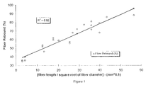
- Figure 1 is a plot of fiber rebound as percent by mass rebounded versus fiber length over the square root of the fiber diameter in millimeters.
- Figure 2 is a side view of a preferred embodiment of one end of a fiber constructed in accordance with the present invention.
- Figure 3 is a plan view looking at the direction of the arrow 3 in Figure 2.
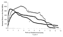
- Figure 4 is a plot of the pullout displacement versus nominal stress in the steel for a commercially available fiber having only a dead anchor, a commercially available fiber having only a drag anchor and for a fiber having a combination of dead and drag anchors constructed in accordance with the preferred embodiment of the present invention.
- Figure 5 is a plot of fiber length versus Shotcrete fracture energy for four different lengths of fiber constructed in accordance with the present invention.
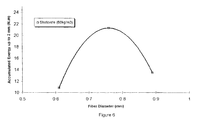
- Figure 6 is a plot of fiber diameter versus Shotcrete fracture energy for three different diameter fibers of the present invention.
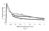
- Figure 7 is a plot of load vs. displacement in flexural toughness testing (ASTM C1018) comparing Shotcrete made using the two different types of commercial fibers used in the tests plotted in Figure 4 with Shotcrete made with fibers constructed in accordance with the present invention (average of at least 4 tests).
- the material used in all of the fibers is steel conventionally used in the manufacture of reinforcing fibers, thus, this disclosure is to be read on the basis that fibers are made from steel or material with equivalent mechanical properties. If a different, but suitable material is to be used the size and shape will have to be modified in accordance with the physical characteristics of the material from which the fibers are made. Obviously, the ductility of the fiber material may render certain materials, in fact many materials, unsuitable for use i.e. materials that are too highly ductile or are too brittle will not be suitable.
- the amount of fiber rebound seriously affects the toughness of the reinforced concrete product in that if the fiber rebounds and is no longer retained within the concrete it cannot function to improve the toughness.
- Figures 2 and 3 show one half (one end) of a preferred fiber constructed in accordance with the present invention i.e. having a preferred fiber geometry.
- the other half is essentially the same as each fiber is symmetrical on opposite sides of its mid length.
- fiber 10 has a diameter d and has a fiber length l f which in the illustrated arrangement is designated by the dimension l f /2 since only half of the fiber length is shown.
- the other half of the fiber is essentially the same as that shown in Figures 2 and 3.
- the fiber is provided with a drag anchor 12 having a length l d and a width w d measured at the maximum width of the drag anchor 12.
- the drag anchor 12 in the illustrated arrangement is a deformity of the fiber diameter to reduce the thickness to t d by deforming the fiber with a die or the like having a radius r g which causes the fiber width to be increased in the reduced thickness area to width w d i.e. width w d in the drag anchor to be greater than the diameter d of the fiber. While it is preferred to use a die with radius r g i.e. a circular shape this in not essential, however care must be taken in deforming the fiber not to form areas or zones of high stress under load in the fiber that may cause the fiber to be prematurely broken.
- a connecting section 16 Adjacent to the axial end 14 of the fiber 10 is a connecting section 16 having a length measured in the axial direction of the fiber indicated at l c (l c is small relative l d or l and in some cases maybe be zero (0)) and adjacent to and preferably extending from the free end 14 of the fiber 10 to the section 16 is a dead anchor 18 having a length l measured in the axial direction of the fiber and thickness t which is significantly less than the thickness t d of the drag anchor 12, and a width w significantly wider than the width w d of the drag section 12.
- a stress concentration or weak point 20 which causes a stress concentration and ensures fiber breakage at the stress concentration point under higher than normal loading conditions.
- This stress concentration point preferably is formed by a neck down section 22 wherein the shape of the fiber is significantly altered to merge into the dead anchor 18 i.e. cross-section of the fiber is significantly flattened and widened (to form the dead anchor which normally will have about the same cross sectional area as the non deformed fiber) over a short length l n formed in the illustrated arrangement by a fillet having a radius r n to define a stress concentration or weak point 20 which provides the breaking point across which the fiber is intended to break in use when the fiber is subjected to a sufficiently high load to develop a stress at the stress concentration point 20 above the breaking point. This breakage occurs to render the dead anchor ineffective and thereby lower the stress levels in the fiber.
- the dead anchor 18 provides sufficient resistance to force being pulled out of the concrete to generate a stress in the fiber higher than can be accommodated by the weak point 20 i.e. the stress at 20 becomes so high that the fiber breaks in the area 20.
- the thickness t and width w which in effect generate the gripping power of the dead anchor 18 in the fiber 10 as illustrated must develop sufficient friction or binding with the concrete so that a pulling force required to generate the stress at the stress concentration point 20 sufficiently high to break the fiber at the weak point 20 may be applied axially in the fiber between the drag 12 and dead anchors 18.
- the flanges or lateral projections 19 and 21 of the dead anchor 18 on opposite sides of the fiber tend to buckle or fold which reduces the resistance to slippage of the dead anchor 18 and renders the dead anchor 18 less effective to carry a high load so that maximum load carrying ability in these cases is reduced by buckling of the dead anchor 18 to reduce the load on the fiber.
- the objective of the invention of ensuring the dead anchor releases to reduce the stress in the fiber may be attained in at least two ways namely by designing the fiber to break at a stress concentration point 20 between the dead 18 and the drag anchors 12 and/or by causing the dead anchor 18 itself to deform and release.
- the geometry of the dead anchor 18 that permits it to release by deformation of the dead anchor at a peak load before breakage at the week point 20 (if a weak point 20 is provided) and in any event to reduce stress in the fiber, for the design shown in Figures 2 and 3, is primarily dependent on the thickness t of the dead anchor 18.
- the stress concentration or weak point 20 may not be the governing factor causing release of the dead anchor it is preferred to include such a point in the fiber design as it may be more accurately designed to ensure stress relief to the fiber under the appropriate load conditions.
- the load carrying capacity of the fiber between the stress concentrating weak points 20 is not exceeded when the fiber breaks at the stress concentrating weak point(s) 20.
- the drag anchor 12 functions in essentially the same way as a conventional drag anchor in conventional reinforcing fiber.
- the maximum drag force or axial force applied to the fiber 10 in order to permit the drag anchor to be dragged through the concrete is less than the maximum force necessary to break the fiber 10.
- the incremental added forces that are carried by the dead anchor 18 under peak conditions cause the stress at the weak point 20 to break the fiber at the weak point 20 or the stresses in the dead anchor to deform the dead anchor 18 and cause it to release.
- the dead anchor 18 functions to reinforce the concrete in one case until breaking occurs at 20 or in the second case until the dead anchor is deformed.
- the energy that can be absorbed by the fiber is substantially greater than can be absorbed using conventional reinforcing fibers with conventional anchor structures. This system permits the application of a higher total pull out load without risk of fiber breakage as the dead anchor releases before the stress in the remainder of the fiber including the drag anchor exceeds its modulus of rupture.
- the drag anchor 12 will be designed to carry at least 80% of the peak load and preferably 90% or higher so that the incremental load carried by the dead anchor is small and the carrying capacity of the fiber is not reduced dramatically when the dead anchor is released.
- Figure 4 shows the effectiveness of the present invention in improving the energy absorption that can be obtained from individual fibers having the anchor of the present invention relative to individual commercially available fibers with anchors.
- the commercial fiber having only a drag anchor (curve 1 in Figure 4) provides a relatively gradual increase in stress as the displacement (pullout) is increased to about 1.5 mm.
- the peak or maximum stress that can be applied is significantly higher, approximately 900 MPa. (tensile strength of the steel used in all cases is 1100 MPa), but the displacement that can be tolerated is less than approximately 1 ⁇ 2 mm.
- the nominal fiber stress quickly diminishes (more so for the dead anchor than the drag anchor) as displacement is increased beyond the point of peak stress.
- the fiber having the combination of the dead and drag anchors 18 and 12 of the present invention shows a very significant increase in stress that can be tolerated i.e. the nominal stress for the fiber reaches above 1000 MPa while accommodating a displacement of about 21 ⁇ 2 mm. and then the allowable stress drops off but does not reduce to that of the commercial drag anchor per se until a very substantial amount of pullout has taken place, i.e. in the order of about 7 mm.
- the weak point 20 fractures or the dead anchor 18 is deformed to release the dead anchor when the peak stress is attained which occurs before the rupture strength of the fiber is reached thereby preventing the fiber rupturing load from being applied to the fiber.
- fibers were made from a fixed diameter wire with a 0.89 mm diameter formed with lengths of 12.5, 19, 25.4 and 40 mm and all were tested at the rate of 60 kg/m 3 in Shotcrete to determine their accumulated fracture energy under flexural loading of a standard ASTM C1018 test on beam specimens 100x100x350 mm. (area under the flexural load versus displacement curve to a displacement of 2 mm). The results obtained are plotted in Figure 5 where it is apparent that a fiber length of somewhere between 20 to 40 mm, preferably about 25 mm, was found to be optimum.
- the dimensions of the fiber illustrated in Figures 2 and 3 were optimized.
- the diameter r g of the indentation forming the drag section 12 was 10.7 mm
- the thickness t d was about 0.46 times diameter d
- the width w d was 1.45 times the diameter d.
- the length l d may be derived.
- the length l of the dead hook section was set at 1.4 the diameter d of the fiber and the thickness t was 0.23 times the diameter d, which produce a width w of 2.36 times the diameter.
- the dimension l c was 0.2 mm and l n and radius r n for this example were equal and less than 0.5 mm.
- one of the preferred embodiments of the present invention for Shotcrete uses a fiber diameter of 0.76 mm, thickness t d of 0.35 mm, width w d of 1.1 mm, thickness t of 0.18 mm and width w of 1.79 mm.
- Fibers as described in the above example were produced in sufficient quantity and tested in a Shotcrete application and compared using standard ASTM C1018 test with 100x100x350 mm. 5 specimens under flexural testing with commercial fibers used for the same application. The results of these tests are plotted in Figure 7 wherein curve A is a plot of the results obtained using the present invention and curve B was obtained using fibers sold under the tradename Dramix by Bekaert and curve C using FE fiber sold by Novocon. It is apparent that the present invention is able to accommodate more load carrying capacity and therefore consume more fracture energy (the area contained by the curves in Figure 7) than either of the two commercial products.
- Fibers for use in cast concrete may for example have significantly longer length than that of fibers for Shotcrete in fact the length may be about doubled.
Landscapes
- Engineering & Computer Science (AREA)
- Architecture (AREA)
- Civil Engineering (AREA)
- Structural Engineering (AREA)
- Reinforcement Elements For Buildings (AREA)
- Yarns And Mechanical Finishing Of Yarns Or Ropes (AREA)
- Artificial Filaments (AREA)
- Piles And Underground Anchors (AREA)
- Curing Cements, Concrete, And Artificial Stone (AREA)
Claims (10)
- Betonbewehrungsfaser (10) mit einem Fasermittel, das einen Zuganker (12) nahe jedem axialen Ende (14) der Faser (10), jedoch von diesem beabstandet, bildet, und einem Mittel, das einen Totanker (18) zwischen jedem den Zuganker (12) bildenden Mittel und dem benachbarten axialen Ende (14) der Faser (10) bildet,
dadurch gekennzeichnet, dass die Faser (10) außerdem ein Totankerfreigabemittel (20) zur Reduzierung der von dem Totanker (18) aufgenommenen Kraft enthält, wenn eine auf die Faser (10) ausgeübte Kraft eine Spannung in dem Freigabemittel (20) hervorruft, die ein ausgewähltes Maximum übersteigt. - Betonbewehrungsfaser (10) nach Anspruch 1,
dadurch gekennzeichnet, dass das Totänkerfreigabemittel (20) ein Mittel enthält, das einen Spannungskonzentrationsschwachpunkt (20) in der Faser (10) zwischen jedem Totanker (18) und dem benachbarten Zuganker (12) bildet. - Betonbewehrungsfaser (10) nach Anspruch 2,
dadurch gekennzeichnet, dass der Schwachpunkt (20) so konstruiert ist, dass er unter Spannung bricht, wenn die Faser (10) einer Gesamtlast ausgesetzt ist, die kleiner ist als die maximale Kraftaufnahmefähigkeit der Faser (10) zwischen den Spannungskonzentrationsschwachpunkten (20), um den Totanker (18) freizugeben, wenn die Faser (10) zwischen den Spannungskonzentrationsschwachpunkten (20) unter einer Kraft steht, die kleiner als die maximale Kraft ist. - Betonbewehrungsfaser (10) nach jedem vorhergehenden Anspruch,
dadurch gekennzeichnet, dass jeder Totanker (18) eine Kraftaufnahmefähigkeit in situ im Beton hat, die kleiner ist als diejenige jedes Zugankers (12). - Betonbewehrungsfaser (10) nach Anspruch 2 oder 3,
dadurch gekennzeichnet, dass die Mittel, die den Spannungskonzentrationsschwachpunkt (20) bilden, ein Bereich der Spannungskonzentration sind, der in der Faser (10) nahe der Stelle ist, an der der Totanker (18) mit der Faser (10) verbunden ist, an einer Seite des Totankers (18) nahe dem benachbarten Zuganker (12). - Betonbewehrungsfaser (10) nach jedem der vorhergehenden Ansprüche,
dadurch gekennzeichnet, dass jeder Zuganker (12) durch ein erstes Paar seitlich vorstehender Seitenflansche gebildet ist, die an beiden gegenüberliegenden Seiten der Faser (10) um eine erste Strecke vorstehen. - Betonbewehrungsfaser (10) nach Anspruch 6,
dadurch gekennzeichnet, dass das erste Paar seitlich sich erstreckender Seitenflansche durch Verformung der Faser (10) gebildet ist, wodurch stellenweise ihre Dicke reduziert ist, ohne Bereiche signifikanter Spannungskonzentrationen hervorzurufen, die die axiale Zugfestigkeit der Faser (10) reduzieren. - Betonbewehrungsfaser (10) nach Anspruch 6 oder 7,
dadurch gekennzeichnet, dass der Abschnitt, der den Totanker (18) bildet, durch eine Verformung der Faser (10) gebildet ist, die ihre Dicke reduziert, um ein zweites Paar seitlich vorstehender Seitenflansche (18, 21) zu bilden, die seitlich von der Faser (10) über eine zweite Strecke abstehen, die größer ist als die erste Strecke. - Betonbewehrungsfaser (10) nach Anspruch 8,
dadurch gekennzeichnet, dass die ersten und zweiten Paare (19, 21) der Flansche im wesentlichen in parallelen Ebenen angeordnet sind. - Betonbewehrungsfaser (10) nach jedem vorhergehenden Anspruch,
dadurch gekennzeichnet, dass die Faser (10) eine Faserlänge zwischen 20 mm und 35 mm und einen Faserdurchmesser zwischen 0,6 mm und 1 mm hat.
Applications Claiming Priority (3)
| Application Number | Priority Date | Filing Date | Title |
|---|---|---|---|
| US920352 | 1997-07-25 | ||
| US08/920,352 US5965277A (en) | 1997-07-25 | 1997-07-25 | Concrete reinforcing fiber |
| PCT/CA1998/000692 WO1999005373A1 (en) | 1997-07-25 | 1998-07-16 | Concrete reinforcing fiber |
Publications (2)
| Publication Number | Publication Date |
|---|---|
| EP1007807A1 EP1007807A1 (de) | 2000-06-14 |
| EP1007807B1 true EP1007807B1 (de) | 2002-10-02 |
Family
ID=25443595
Family Applications (1)
| Application Number | Title | Priority Date | Filing Date |
|---|---|---|---|
| EP98933417A Expired - Lifetime EP1007807B1 (de) | 1997-07-25 | 1998-07-16 | Betonbewehrungsfaser |
Country Status (12)
| Country | Link |
|---|---|
| US (1) | US5965277A (de) |
| EP (1) | EP1007807B1 (de) |
| JP (1) | JP2001511428A (de) |
| KR (1) | KR20010022199A (de) |
| AT (1) | ATE225445T1 (de) |
| AU (1) | AU727902B2 (de) |
| BR (1) | BR9811291A (de) |
| CA (1) | CA2294123A1 (de) |
| DE (1) | DE69808495T2 (de) |
| NZ (1) | NZ502331A (de) |
| WO (1) | WO1999005373A1 (de) |
| ZA (1) | ZA986610B (de) |
Families Citing this family (13)
| Publication number | Priority date | Publication date | Assignee | Title |
|---|---|---|---|---|
| US20060124271A1 (en) * | 2004-12-13 | 2006-06-15 | Mark Schlichting | Method of controlling the formation of crocodile skin surface roughness on thin cast strip |
| US8312917B2 (en) * | 2004-12-13 | 2012-11-20 | Nucor Corporation | Method and apparatus for controlling the formation of crocodile skin surface roughness on thin cast strip |
| US7891407B2 (en) * | 2004-12-13 | 2011-02-22 | Nucor Corporation | Method and apparatus for localized control of heat flux in thin cast strip |
| EP1948438A4 (de) * | 2005-11-14 | 2010-04-07 | Polymer Group Inc | Verbundverstärkungsfaser mit verbesserten biegeeigenschaften, giessbare produkte damit und verfahren |
| CN102459776B (zh) | 2009-06-12 | 2016-08-10 | 贝卡尔特公司 | 具有良好锚固性的高伸长率纤维 |
| KR102369006B1 (ko) * | 2009-06-12 | 2022-03-02 | 엔브이 베카에르트 에스에이 | 고 신장성 파이버 |
| BE1021496B1 (nl) | 2010-12-15 | 2015-12-03 | Nv Bekaert Sa | Staalvezel voor het wapenen van beton of mortel, met een verankeringseinde met ten minste twee gebogen secties |
| BE1021498B1 (nl) | 2010-12-15 | 2015-12-03 | Nv Bekaert Sa | Staalvezel voor het wapenen van beton of mortel, met een verankeringseinde met tenminste drie rechte secties |
| CN104995360A (zh) | 2013-01-31 | 2015-10-21 | 欧普特艾美特混凝土产品股份有限公司 | 用于混凝土加固的三维形变纤维 |
| USD717156S1 (en) * | 2013-06-28 | 2014-11-11 | Hagihara Industries Inc. | Fibrous concrete reinforcement |
| EP3490952B1 (de) | 2016-05-24 | 2023-10-04 | NeoCrest LLC | Polymere fasern zur verstärkung von zementbasierten verbundstoffen |
| US10639748B2 (en) | 2017-02-24 | 2020-05-05 | Lincoln Global, Inc. | Brazed electrode for plasma cutting torch |
| CN117001844A (zh) * | 2023-06-27 | 2023-11-07 | 山东大学 | 一种纤维定向的方法及基于此制备的纤维混凝土 |
Family Cites Families (15)
| Publication number | Priority date | Publication date | Assignee | Title |
|---|---|---|---|---|
| US1349901A (en) * | 1918-12-16 | 1920-08-17 | Meischke-Smith William | Ferroconcrete construction |
| US2677955A (en) * | 1943-02-12 | 1954-05-11 | Constantinesco George | Reinforced concrete |
| US3900667A (en) * | 1969-09-12 | 1975-08-19 | Bekaert Sa Nv | Reinforcing wire element and materials reinforced therewith |
| AR206305A1 (es) * | 1972-11-28 | 1976-07-15 | Australian Wire Ind Pty | Fibras de refuerzo para materiales de matriz moldeables metodo y aparato para producirla |
| US4233364A (en) * | 1979-05-15 | 1980-11-11 | Van Thiel's Draadindustrie (Thibodraad) B.V. | Anchoring fibre for use in concrete |
| JPS58181439A (ja) * | 1982-04-16 | 1983-10-24 | Yoshitomo Tezuka | コンクリ−ト補強用鋼繊維 |
| US4883713A (en) * | 1986-04-28 | 1989-11-28 | Eurosteel S.A. | Moldable material reinforcement fibers with hydraulic or non-hydraulic binder and manufacturing thereof |
| US4804585A (en) * | 1986-09-26 | 1989-02-14 | Kabushiki Kaisha Kobe Seiko Sho | Concrete reinforcing steel fibers and a method of manufacturing the same |
| CA1307677C (en) * | 1987-11-25 | 1992-09-22 | Susumu Takata | Reinforcing metal fibers |
| WO1991019059A1 (en) * | 1990-06-01 | 1991-12-12 | Domecrete Ltd. | Reinforcing element |
| IT1241027B (it) * | 1990-09-12 | 1993-12-27 | Ilm Tps S P A | Fibra metallica per il rinforzo di calcestruzzo ed apparecchiatura per la sua fabbricazione. |
| DE4120177C1 (de) * | 1991-06-19 | 1992-06-04 | Leslot Industriebedarf Gmbh, 4300 Essen, De | |
| BE1005815A3 (nl) * | 1992-05-08 | 1994-02-08 | Bekaert Sa Nv | Staalvezelbeton met hoge buigtreksterkte. |
| CA2112934A1 (en) * | 1993-01-21 | 1994-07-22 | Robert Hugo Jacob Over | Reinforcement fibre for reinforcing concrete |
| US5443918A (en) * | 1994-09-07 | 1995-08-22 | Universite Laval | Metal fiber with optimized geometry for reinforcing cement-based materials |
-
1997
- 1997-07-25 US US08/920,352 patent/US5965277A/en not_active Expired - Fee Related
-
1998
- 1998-07-16 WO PCT/CA1998/000692 patent/WO1999005373A1/en not_active Ceased
- 1998-07-16 BR BR9811291-0A patent/BR9811291A/pt not_active Application Discontinuation
- 1998-07-16 EP EP98933417A patent/EP1007807B1/de not_active Expired - Lifetime
- 1998-07-16 KR KR1020007000771A patent/KR20010022199A/ko not_active Ceased
- 1998-07-16 CA CA002294123A patent/CA2294123A1/en not_active Abandoned
- 1998-07-16 AU AU83298/98A patent/AU727902B2/en not_active Ceased
- 1998-07-16 NZ NZ502331A patent/NZ502331A/xx unknown
- 1998-07-16 JP JP2000504336A patent/JP2001511428A/ja not_active Withdrawn
- 1998-07-16 DE DE69808495T patent/DE69808495T2/de not_active Expired - Fee Related
- 1998-07-16 AT AT98933417T patent/ATE225445T1/de not_active IP Right Cessation
- 1998-07-24 ZA ZA9806610A patent/ZA986610B/xx unknown
Also Published As
| Publication number | Publication date |
|---|---|
| WO1999005373A1 (en) | 1999-02-04 |
| JP2001511428A (ja) | 2001-08-14 |
| NZ502331A (en) | 2000-12-22 |
| CA2294123A1 (en) | 1999-02-04 |
| DE69808495D1 (de) | 2002-11-07 |
| EP1007807A1 (de) | 2000-06-14 |
| BR9811291A (pt) | 2000-08-29 |
| US5965277A (en) | 1999-10-12 |
| AU727902B2 (en) | 2001-01-04 |
| ZA986610B (en) | 2000-01-24 |
| DE69808495T2 (de) | 2003-02-20 |
| AU8329898A (en) | 1999-02-16 |
| KR20010022199A (ko) | 2001-03-15 |
| ATE225445T1 (de) | 2002-10-15 |
| HK1030249A1 (en) | 2001-04-27 |
Similar Documents
| Publication | Publication Date | Title |
|---|---|---|
| EP2652222B1 (de) | Stahlfaserverstärkter beton | |
| EP1007807B1 (de) | Betonbewehrungsfaser | |
| EP2652221B1 (de) | Stahlfaserverstärkter beton | |
| US6060163A (en) | Optimized geometries of fiber reinforcement of cement, ceramic and polymeric based composites | |
| EP2440718B1 (de) | Betonstruktur mit fasern mit hoher streckung und guter verankerung | |
| US6082063A (en) | Prestressing anchorage system for fiber reinforced plastic tendons | |
| US5443918A (en) | Metal fiber with optimized geometry for reinforcing cement-based materials | |
| EP2440717B1 (de) | Stahlfaser mit hoher Dehnfähigkeit für herkömmlichen Beton | |
| JPH06115988A (ja) | スチールファイバー補強コンクリート材料 | |
| Zhang et al. | Tensile behavior analysis and prediction of steel fiber-reinforced-carbon/glass hybrid composite bars | |
| Peyvandi et al. | Experimental investigation on the performance of engineered spiral fiber: Fiber pull-out and direct tension tests | |
| HK1030249B (en) | Concrete reinforcing fiber | |
| EP2652220B1 (de) | Stahlfaser zur verstärkung von beton oder mörtel mit abgeflachten abschnitten | |
| Banthia et al. | A double anchored (DD) steel fiber for shotcrete | |
| EP0725871B1 (de) | Metallfaser mit optimierter geometrie zur verstärkung von zementmaterialien | |
| MXPA00000766A (en) | Concrete reinforcing fiber | |
| KR200298950Y1 (ko) | 보강재로 섬유강화 플라스틱 바를 사용하는 콘크리트구조물 | |
| WO2008095211A1 (de) | Scheibenförmige körper für fasern | |
| KR20040025331A (ko) | 보강재로 섬유강화 플라스틱 바를 사용하는 콘크리트구조물 | |
| AT504665B1 (de) | Scheibenförmige körper für fasern |
Legal Events
| Date | Code | Title | Description |
|---|---|---|---|
| PUAI | Public reference made under article 153(3) epc to a published international application that has entered the european phase |
Free format text: ORIGINAL CODE: 0009012 |
|
| 17P | Request for examination filed |
Effective date: 20000126 |
|
| AK | Designated contracting states |
Kind code of ref document: A1 Designated state(s): AT BE CH CY DE DK ES FI FR GB GR IE IT LI LU MC NL PT SE |
|
| AX | Request for extension of the european patent |
Free format text: RO PAYMENT 20000126;SI PAYMENT 20000126 |
|
| RIN1 | Information on inventor provided before grant (corrected) |
Inventor name: ARMELIN, HUGO, S. Inventor name: BANTHIA, NEMKURNAR |
|
| 17Q | First examination report despatched |
Effective date: 20010705 |
|
| GRAG | Despatch of communication of intention to grant |
Free format text: ORIGINAL CODE: EPIDOS AGRA |
|
| GRAG | Despatch of communication of intention to grant |
Free format text: ORIGINAL CODE: EPIDOS AGRA |
|
| GRAH | Despatch of communication of intention to grant a patent |
Free format text: ORIGINAL CODE: EPIDOS IGRA |
|
| GRAH | Despatch of communication of intention to grant a patent |
Free format text: ORIGINAL CODE: EPIDOS IGRA |
|
| GRAA | (expected) grant |
Free format text: ORIGINAL CODE: 0009210 |
|
| AK | Designated contracting states |
Kind code of ref document: B1 Designated state(s): AT BE CH CY DE DK ES FI FR GB GR IE IT LI LU MC NL PT SE |
|
| AX | Request for extension of the european patent |
Free format text: RO PAYMENT 20000126;SI PAYMENT 20000126 |
|
| PG25 | Lapsed in a contracting state [announced via postgrant information from national office to epo] |
Ref country code: NL Free format text: LAPSE BECAUSE OF FAILURE TO SUBMIT A TRANSLATION OF THE DESCRIPTION OR TO PAY THE FEE WITHIN THE PRESCRIBED TIME-LIMIT Effective date: 20021002 Ref country code: IT Free format text: LAPSE BECAUSE OF FAILURE TO SUBMIT A TRANSLATION OF THE DESCRIPTION OR TO PAY THE FEE WITHIN THE PRESCRIBED TIME-LIMIT;WARNING: LAPSES OF ITALIAN PATENTS WITH EFFECTIVE DATE BEFORE 2007 MAY HAVE OCCURRED AT ANY TIME BEFORE 2007. THE CORRECT EFFECTIVE DATE MAY BE DIFFERENT FROM THE ONE RECORDED. Effective date: 20021002 Ref country code: GR Free format text: LAPSE BECAUSE OF FAILURE TO SUBMIT A TRANSLATION OF THE DESCRIPTION OR TO PAY THE FEE WITHIN THE PRESCRIBED TIME-LIMIT Effective date: 20021002 Ref country code: FI Free format text: LAPSE BECAUSE OF FAILURE TO SUBMIT A TRANSLATION OF THE DESCRIPTION OR TO PAY THE FEE WITHIN THE PRESCRIBED TIME-LIMIT Effective date: 20021002 Ref country code: BE Free format text: LAPSE BECAUSE OF FAILURE TO SUBMIT A TRANSLATION OF THE DESCRIPTION OR TO PAY THE FEE WITHIN THE PRESCRIBED TIME-LIMIT Effective date: 20021002 Ref country code: AT Free format text: LAPSE BECAUSE OF FAILURE TO SUBMIT A TRANSLATION OF THE DESCRIPTION OR TO PAY THE FEE WITHIN THE PRESCRIBED TIME-LIMIT Effective date: 20021002 |
|
| REF | Corresponds to: |
Ref document number: 225445 Country of ref document: AT Date of ref document: 20021015 Kind code of ref document: T |
|
| REG | Reference to a national code |
Ref country code: GB Ref legal event code: FG4D |
|
| REG | Reference to a national code |
Ref country code: CH Ref legal event code: EP |
|
| REG | Reference to a national code |
Ref country code: IE Ref legal event code: FG4D |
|
| REF | Corresponds to: |
Ref document number: 69808495 Country of ref document: DE Date of ref document: 20021107 |
|
| PG25 | Lapsed in a contracting state [announced via postgrant information from national office to epo] |
Ref country code: SE Free format text: LAPSE BECAUSE OF FAILURE TO SUBMIT A TRANSLATION OF THE DESCRIPTION OR TO PAY THE FEE WITHIN THE PRESCRIBED TIME-LIMIT Effective date: 20030102 Ref country code: PT Free format text: LAPSE BECAUSE OF FAILURE TO SUBMIT A TRANSLATION OF THE DESCRIPTION OR TO PAY THE FEE WITHIN THE PRESCRIBED TIME-LIMIT Effective date: 20030102 Ref country code: DK Free format text: LAPSE BECAUSE OF FAILURE TO SUBMIT A TRANSLATION OF THE DESCRIPTION OR TO PAY THE FEE WITHIN THE PRESCRIBED TIME-LIMIT Effective date: 20030102 |
|
| REG | Reference to a national code |
Ref country code: CH Ref legal event code: NV Representative=s name: KIRKER & CIE SA |
|
| NLV1 | Nl: lapsed or annulled due to failure to fulfill the requirements of art. 29p and 29m of the patents act | ||
| ET | Fr: translation filed | ||
| PG25 | Lapsed in a contracting state [announced via postgrant information from national office to epo] |
Ref country code: ES Free format text: LAPSE BECAUSE OF FAILURE TO SUBMIT A TRANSLATION OF THE DESCRIPTION OR TO PAY THE FEE WITHIN THE PRESCRIBED TIME-LIMIT Effective date: 20030429 |
|
| PG25 | Lapsed in a contracting state [announced via postgrant information from national office to epo] |
Ref country code: LU Free format text: LAPSE BECAUSE OF NON-PAYMENT OF DUE FEES Effective date: 20030716 Ref country code: IE Free format text: LAPSE BECAUSE OF NON-PAYMENT OF DUE FEES Effective date: 20030716 Ref country code: CY Free format text: LAPSE BECAUSE OF FAILURE TO SUBMIT A TRANSLATION OF THE DESCRIPTION OR TO PAY THE FEE WITHIN THE PRESCRIBED TIME-LIMIT Effective date: 20030716 |
|
| PG25 | Lapsed in a contracting state [announced via postgrant information from national office to epo] |
Ref country code: MC Free format text: LAPSE BECAUSE OF NON-PAYMENT OF DUE FEES Effective date: 20030731 |
|
| PLBE | No opposition filed within time limit |
Free format text: ORIGINAL CODE: 0009261 |
|
| STAA | Information on the status of an ep patent application or granted ep patent |
Free format text: STATUS: NO OPPOSITION FILED WITHIN TIME LIMIT |
|
| 26N | No opposition filed |
Effective date: 20030703 |
|
| REG | Reference to a national code |
Ref country code: IE Ref legal event code: MM4A |
|
| PGFP | Annual fee paid to national office [announced via postgrant information from national office to epo] |
Ref country code: FR Payment date: 20040621 Year of fee payment: 7 |
|
| PGFP | Annual fee paid to national office [announced via postgrant information from national office to epo] |
Ref country code: DE Payment date: 20040726 Year of fee payment: 7 |
|
| PGFP | Annual fee paid to national office [announced via postgrant information from national office to epo] |
Ref country code: CH Payment date: 20041015 Year of fee payment: 7 |
|
| PGFP | Annual fee paid to national office [announced via postgrant information from national office to epo] |
Ref country code: GB Payment date: 20050714 Year of fee payment: 8 |
|
| PG25 | Lapsed in a contracting state [announced via postgrant information from national office to epo] |
Ref country code: LI Free format text: LAPSE BECAUSE OF NON-PAYMENT OF DUE FEES Effective date: 20050731 Ref country code: CH Free format text: LAPSE BECAUSE OF NON-PAYMENT OF DUE FEES Effective date: 20050731 |
|
| PG25 | Lapsed in a contracting state [announced via postgrant information from national office to epo] |
Ref country code: DE Free format text: LAPSE BECAUSE OF NON-PAYMENT OF DUE FEES Effective date: 20060201 |
|
| REG | Reference to a national code |
Ref country code: CH Ref legal event code: PL |
|
| PG25 | Lapsed in a contracting state [announced via postgrant information from national office to epo] |
Ref country code: FR Free format text: LAPSE BECAUSE OF NON-PAYMENT OF DUE FEES Effective date: 20060331 |
|
| REG | Reference to a national code |
Ref country code: FR Ref legal event code: ST Effective date: 20060331 |
|
| PG25 | Lapsed in a contracting state [announced via postgrant information from national office to epo] |
Ref country code: GB Free format text: LAPSE BECAUSE OF NON-PAYMENT OF DUE FEES Effective date: 20060716 |
|
| GBPC | Gb: european patent ceased through non-payment of renewal fee |
Effective date: 20060716 |