EP1007793B1 - Automatic static load testing for piles - Google Patents
Automatic static load testing for piles Download PDFInfo
- Publication number
- EP1007793B1 EP1007793B1 EP98909616A EP98909616A EP1007793B1 EP 1007793 B1 EP1007793 B1 EP 1007793B1 EP 98909616 A EP98909616 A EP 98909616A EP 98909616 A EP98909616 A EP 98909616A EP 1007793 B1 EP1007793 B1 EP 1007793B1
- Authority
- EP
- European Patent Office
- Prior art keywords
- load
- test
- pile
- magnitude
- electronic computer
- Prior art date
- Legal status (The legal status is an assumption and is not a legal conclusion. Google has not performed a legal analysis and makes no representation as to the accuracy of the status listed.)
- Expired - Lifetime
Links
- 238000012360 testing method Methods 0.000 title claims description 84
- 230000003068 static effect Effects 0.000 title claims description 23
- 238000006073 displacement reaction Methods 0.000 claims description 48
- 238000000034 method Methods 0.000 claims description 18
- 238000006243 chemical reaction Methods 0.000 claims description 15
- 230000001960 triggered effect Effects 0.000 claims description 13
- 239000012530 fluid Substances 0.000 claims description 8
- 238000004891 communication Methods 0.000 claims description 5
- 230000004044 response Effects 0.000 claims description 5
- 238000010998 test method Methods 0.000 claims description 2
- 238000005259 measurement Methods 0.000 description 9
- 239000007789 gas Substances 0.000 description 5
- 230000008859 change Effects 0.000 description 4
- 238000009434 installation Methods 0.000 description 3
- 238000012544 monitoring process Methods 0.000 description 3
- IJGRMHOSHXDMSA-UHFFFAOYSA-N Atomic nitrogen Chemical compound N#N IJGRMHOSHXDMSA-UHFFFAOYSA-N 0.000 description 2
- 238000012937 correction Methods 0.000 description 2
- 230000000694 effects Effects 0.000 description 2
- 230000008569 process Effects 0.000 description 2
- 238000012545 processing Methods 0.000 description 2
- 230000000750 progressive effect Effects 0.000 description 2
- 230000000717 retained effect Effects 0.000 description 2
- OKTJSMMVPCPJKN-UHFFFAOYSA-N Carbon Chemical compound [C] OKTJSMMVPCPJKN-UHFFFAOYSA-N 0.000 description 1
- 241000876833 Emberizinae Species 0.000 description 1
- 238000013459 approach Methods 0.000 description 1
- 230000008901 benefit Effects 0.000 description 1
- 229910052799 carbon Inorganic materials 0.000 description 1
- 238000009833 condensation Methods 0.000 description 1
- 230000005494 condensation Effects 0.000 description 1
- 239000004020 conductor Substances 0.000 description 1
- 238000013270 controlled release Methods 0.000 description 1
- 230000003247 decreasing effect Effects 0.000 description 1
- 238000013461 design Methods 0.000 description 1
- 238000005265 energy consumption Methods 0.000 description 1
- 230000008713 feedback mechanism Effects 0.000 description 1
- 230000005669 field effect Effects 0.000 description 1
- 230000008014 freezing Effects 0.000 description 1
- 238000007710 freezing Methods 0.000 description 1
- 230000004886 head movement Effects 0.000 description 1
- 229910044991 metal oxide Inorganic materials 0.000 description 1
- 150000004706 metal oxides Chemical class 0.000 description 1
- 238000012986 modification Methods 0.000 description 1
- 230000004048 modification Effects 0.000 description 1
- 229910052757 nitrogen Inorganic materials 0.000 description 1
- 239000004065 semiconductor Substances 0.000 description 1
- 238000004904 shortening Methods 0.000 description 1
- 238000012956 testing procedure Methods 0.000 description 1
- 238000012546 transfer Methods 0.000 description 1
Images

Classifications
-
- G—PHYSICS
- G01—MEASURING; TESTING
- G01M—TESTING STATIC OR DYNAMIC BALANCE OF MACHINES OR STRUCTURES; TESTING OF STRUCTURES OR APPARATUS, NOT OTHERWISE PROVIDED FOR
- G01M5/00—Investigating the elasticity of structures, e.g. deflection of bridges or air-craft wings
- G01M5/0041—Investigating the elasticity of structures, e.g. deflection of bridges or air-craft wings by determining deflection or stress
- G01M5/005—Investigating the elasticity of structures, e.g. deflection of bridges or air-craft wings by determining deflection or stress by means of external apparatus, e.g. test benches or portable test systems
-
- E—FIXED CONSTRUCTIONS
- E02—HYDRAULIC ENGINEERING; FOUNDATIONS; SOIL SHIFTING
- E02D—FOUNDATIONS; EXCAVATIONS; EMBANKMENTS; UNDERGROUND OR UNDERWATER STRUCTURES
- E02D33/00—Testing foundations or foundation structures
-
- G—PHYSICS
- G01—MEASURING; TESTING
- G01L—MEASURING FORCE, STRESS, TORQUE, WORK, MECHANICAL POWER, MECHANICAL EFFICIENCY, OR FLUID PRESSURE
- G01L5/00—Apparatus for, or methods of, measuring force, work, mechanical power, or torque, specially adapted for specific purposes
- G01L5/0028—Force sensors associated with force applying means
- G01L5/0038—Force sensors associated with force applying means applying a pushing force
-
- G—PHYSICS
- G01—MEASURING; TESTING
- G01N—INVESTIGATING OR ANALYSING MATERIALS BY DETERMINING THEIR CHEMICAL OR PHYSICAL PROPERTIES
- G01N3/00—Investigating strength properties of solid materials by application of mechanical stress
- G01N3/08—Investigating strength properties of solid materials by application of mechanical stress by applying steady tensile or compressive forces
Definitions
- the present invention relates to a method and apparatus for testing the static load-bearing capacity of engineering piles.
- Piles are generally used to form the foundations of buildings or other large structures. Before using the piles as a foundation for further building work, it is important to test the static load-bearing capacity of each pile. This is generally done by applying a test load to the top of a pile by way of a hydraulic jack braced against a reaction system comprising a cross-beam which is anchored in place at its ends. The test load is generally measured by monitoring the hydraulic pressure supplied to the jack, and the associated displacement of the pile is measured by using a displacement sensor. Frequently, the displacement of the pile is measured for a number of increasing test loads, each applied for a predetermined time. Because the applied test loads tend to be high, there is a significant danger to operating personnel should the cross-beam or its anchorages fail, particularly if the operating personnel are required to read test values from a gauges located on equipment located close to the top of the pile.
- an apparatus for testing the static load-bearing capacity of a pile comprising:
- the present invention allows a much more detailed analysis of the structural integrity of the pile to be obtained. This analysis can be presented in real-time, advantageously in tabulated and/or graphic form, and reduces the risk of errors being introduced through manual processing of the data.
- operating signals may be sent to the jack in order, for example, to maintain a given test load even when the pile is being displaced. This means that a given test load can be applied for a long period of time without the need for operating personnel to be present in order manually to adjust the applied load.
- the computer can be arranged so as to control the jack to apply a number of different test loads to the pile, each for a predetermined minimum period of time or until a definite settlement rate has been achieved. In order to do this, the required load steps and intervals may be defined, together a specific settlement rate.
- the computer can then control the test load and make the required load changes as required. Load changes may be performed by successively increasing the applied load in small increments until the next desired substantially constant load level is achieved. If the settlement rate during the load change exceeds a predetermined maximum value, then the increase of the applied load may be paused until the settlement rate stabilises.
- the jack is a hydraulic jack controlled by the computer by way of a hydraulic control system.
- the applied test load may be calculated by monitoring the fluid pressure in the hydraulic control system driving the jack.
- This method has the disadvantage that it is temperature sensitive (due to thermal expansion of the hydraulic fluid), and does not take into account friction between the jack and the point of contact on the top of the pile in the event that the test load is being applied eccentrically.
- one or more electronic load cells which typically employ balanced strain gauges around a coaxial element. These may be placed above the jack on a spherical seating arrangement so as to reduce the risk of eccentric loading. Because the load cells measure the actual load applied to the pile, it is possible to operate the jack by way of the hydraulic control system so as to apply a substantially constant load, even when the pile is undergoing displacement. This feedback mechanism allows the applied load to be held constant to a degree hitherto not possible with manually-operated systems.
- the time interval between successive measurements of applied load and pile displacement can be of the order of a few seconds, say from 1 to 5 seconds.
- the computer is arranged so as to halt the testing process automatically, for example by stopping the flow of hydraulic fluid to the jack, when certain conditions are detected.
- This automatic fail-safe procedure is a further advantage over the known methods of static load-testing, and allows the present invention to be left unattended without undue risk.
- the fail-safe condition may be triggered in the following situations:
- an additional displacement sensor is provided in order to detect any gradual upward movement of the reaction member, which is indicative of a gradual failure of the reaction system. This is because a gradual failure of this sort, which may be caused by an anchor pile being pulled from the ground, may still allow the load applied to the top of the pile to be maintained.
- the ram extension of the jack may be monitored by measuring the volume of hydraulic fluid pumped to the jack by the hydraulic control system. This may be achieved by using a volumetric flowmeter, determining the level of hydraulic fluid in a reservoir of known size with a float or other means, or by any other suitable method. When the ram extension reaches or exceeds a predetermined value, this may be an indication of a failure in the reaction system or of a progressive failure in the pile, and a fail-safe signal is then generated so as to halt the testing process.
- the area surrounding a pile test being undertaken in accordance with the present invention may be cordoned off with bunting, and a fine wire conductor system or trip wire may be installed so as to detect unauthorised access to the test site.
- the computer is advantageously configured so as to trigger the fail-safe condition in this event.
- an alarm signal may be generated.
- This alarm signal may be transmitted to an operator or to a remote site by way of a mobile telephone or radio link, or by any other suitable method.
- data and control signals may be transmitted from and received by the computer so as to allow remote interrogation and control.
- FIG. 1 shows a static load testing rig suitable for use in the present invention.
- This rig comprises a jack 1 braced between the top of a pile 2 and a reaction member 3.
- the reaction member 3 is anchored to the ground by way of two support towers 4, each of which is firmly attached to the ground by way of one or more auxiliary piles 5.
- An electronic load cell 6 is mounted between the jack 1 and the top of the pile 2, and is connected to a data logger 7.
- Displacement sensors 8 are mounted around the pile 2 and are used to measure the displacement of the pile 2 relative to a reference frame 9.
- the displacement sensors 8 are also connected to the data logger 7.
- a hydraulic control system 10, which will be described hereinafter in more detail, serves to control the jack 1. Both the data logger 7 and the hydraulic control system 10 are operatively linked to a host computer 11.
- the data logger 7 may be a "CR10", which is a data logging computer available from Campbell Scientific and often used, for example, in weather balloons.
- the data logger 7 can readily be programmed to regulate all the functions, measuring the displacement sensors 8 at intervals of, for example, 2.5 seconds and recording the data at chosen intervals. It also checks the load applied to the pile 2 at each interval and effects any change required to the applied load by controlling the hydraulic pressure feeding the jack 1.
- the data logger 7 may also be programmed to check the safe progress of the test and to control all of the load changes required.
- the measurement monitoring and control is carried out by a suitably programmed CR10 data logger 7, which is battery-powered and can store up to 30,000 data values.
- the acquisition and processing functions are controlled by user-entered instructions in program form which are downloaded via a standard RS232 communications data link from a host PC (Personal Computer) 11 which acts also as a display terminal to view the actual data being monitored by the data logger 7.
- the PC 11 can also receive and store the last data recorded by the data logger 7 so that it remains updated and does not require the transfer of all the data every time a connection is made.
- the host PC 11 acts as a display terminal while all the control and measurement functions are performed by the data logger 7 itself.
- the data communications link can also be over a modem or digital mobile radio or telephone link.
- the data logger 7 Among the in-built functions of the data logger 7 is a four-wire full bridge measurement facility with temperature compensation, which is employed to monitor the load cell 6.
- the standard analogue input channels are used for the measurement of the displacement sensors 8. For these measurements a resolution of 333 ⁇ V on the selected full scale range of 2.5V is quoted. For an ideal displacement sensor of 100mm travel, this equates to a resolution of 0.013mm.
- Two selector switches can be connected to the digital channels allowing manual selection of the operation mode from: i) standby, ii) datum, iii) reading and iv) logging; and selection of the interval of data logging from: i) 10 seconds, ii) 1 minute, iii) 5 minutes and iv) 10 minutes.
- the operation mode allows program flow control to provide storage of the datum values so that subsequent readings take any offsets into account directly.
- a ten turn potentiometer (not shown) is provided on the front panel with a digital readout which provides for manual input to the data logger 7 of the desired load. Exact calibration of this variable resistance is not found necessary as the interpreted desired load is displayed directly on the screen of the PC 11.
- a facility in the control software is also included to lock off any further subsequent readings of this potentiometer, since it is found that the chosen desired load is not always as constant as might be expected: once this facility is included in the program, the parameter location can be made directly accessible from the host PC 11 and can be changed precisely. The potentiometer can be retained as a back-up solution.
- a data set is programmed to consist of date and time, the readings of the displacement sensors 8 and the actual load measured together wich the desired load.
- the power for the data logger 7 is derived from an uninterruptable power supply (not shown) which is arranged with a 16A/h battery back-up, which gives a minimum of five days continuous logging on a fully-charged battery. Because the operation of the system can be practically continuous, portable generators 12 may be used to provide the mains power for the host PC 11 and simultaneously to charge the battery when possible.
- a further feature of the CR10 data logger 7 is that it can be programmed to control several output ports which are conveniently arranged to operate the hydraulic control system 10 which includes a pneumatic to hydraulic pump 13 to increase applied load and to operate an oil solenoid 14 to allow the jack pressure to be decreased as required.
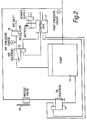
- the output from the appropriate data logger channels are employed to drive MOSFETs (metal-oxide semiconductor field effect transistors) which switch the respective solenoids 14, 15 in the hydraulic control system 10, which is shown in more detail in Figure 2.
- a gas solenoid 15 primes the hydraulic pump 13 from a 100psi (689kPa) supply.
- This gas supply may be generated from an air compressor (not shown) or more conveniently from a gas bottle 20.
- the preferred choice is the use of gas bottles filled with oxygen-free nitrogen. This gas is dry, minimising condensation and subsequent freezing inside the pump relief valve which can impede its correct operation in cold weather.
- the electronically-controlled release of hydraulic pressure uses a high pressure oil solenoid 14 through a needle valve 16 to control the rate of discharge.
- the connections to the data logger 7, by way of a control box 17, provide a switched return path for operation of the solenoids 14, 15.
- the load application to the head of the pile 2 is carried out by the use of a hydraulic jack 1; hydraulic pressure is produced by use of a suitable pump 13, 18.
- a manually-operated hand pump 18 is adequate for coarse load control. This aspect of the conventional test arrangement may be retained for two principal reasons: i) the manual pump 18 may be used to allow the jack 1 to take up any slack between the load cell 6 and the reaction frame 3, and ii) in the unlikely event of failure of the automatic load control system, the test can be continued manually.
- a Maximator ® "S"-type air-driven hydraulic pump 13 may be used in the automatic load control system 10.
- This pump works on a differential area piston principle, applying air to the large surface area of the air drive piston (not shown) which is mechanically connected to a smaller hydraulic piston (not shown). This converts pneumatic energy into hydraulic power.
- Automatic changeover of pistons is achieved by a pilot valve triggered by a servo slide valve (not shown). This valve has no pressure balance control, therefore eliminating stalling during normal operation.
- the pump 13 cycles more slowly as it approaches the specified maximum pressure and stops, when hydraulic and air pressure forces are in balance. The pump 13 then maintains the specified pressure output without further intervention or energy consumption.
- the magnitude of any load correction required may be determined within the data logger 7 every 2.5 seconds; this is then translated into timing signals which are made to operate an increase or a decrease of the hydraulic pressure.
- a scaling factor is employed to make the system sufficiently versatile to accommodate varying sizes of jack 1 and perform successfully the two principal functions: a) maintain the load within tight boundaries, and b) change the load when required.
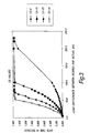
- a simple control algorithm may be employed to determine the duration of a control pulse which opens a pneumatic valve 19 for a predetermined period which should correspond to the load change required.
- Figure 3 indicates the resultant variation with this coefficient on the pulse applied to the control switches of the hydraulic control system 10.
- the operation of the timing circuits is usually limited to a maximum of approximately 1.5 seconds. It is usually less than the 2.5 seconds program cycle to ensure correct operation of the software.
- a significant bonus in introducing a computerised hydraulic control system 10 is that the load applied can be held truly constant within tight controllable limits. As a consequence, the displacement in time of the foundation system under test is not distorted by induced load variations.
- sensors 8 are commercially available, allowing total displacements of up to 250mm to be measured with excellent resolution.
- the currently preferred and most reliable sensors 8 are resistive elements which employ a carbon strip such as those from Penny & Giles (typical ref: HLP190/FS1/100/4k).
- a modification required on some of the sensors is the installation of a return spring (not shown) to ensure that the travel of the arm of the sensor is sprung loaded to its fully-extended position; Penny & Giles offer a sprung-loaded sensor.
- the sensor 8 also requires the installation of a suitable mounting arrangement which allows the gauges to be secured and rapidly attached to the reference frame 9.
- Calibration of the displacement sensors 8 is also desirable to ensure that constancy between different sensors 8 is maintained.
- This calibration may be carried out against a digital vernier calliper; it should be noted that one of the largest inaccuracies encountered during calibration is the verticality of the gauge with respect to the reference standard. This only becomes significant when high accuracy is being sought as repeatability of measurement with just a 0.1° variation, which represents less than 1:1000, can be equated to a variation of displacement of 0.1%. This inaccuracy with verticality of the gauge is also applicable to measurement of pile head movement.
Landscapes
- Physics & Mathematics (AREA)
- General Physics & Mathematics (AREA)
- Engineering & Computer Science (AREA)
- Chemical & Material Sciences (AREA)
- Analytical Chemistry (AREA)
- Life Sciences & Earth Sciences (AREA)
- General Engineering & Computer Science (AREA)
- Health & Medical Sciences (AREA)
- Paleontology (AREA)
- Civil Engineering (AREA)
- General Life Sciences & Earth Sciences (AREA)
- Structural Engineering (AREA)
- Aviation & Aerospace Engineering (AREA)
- Mining & Mineral Resources (AREA)
- Biochemistry (AREA)
- General Health & Medical Sciences (AREA)
- Immunology (AREA)
- Pathology (AREA)
- Investigating Strength Of Materials By Application Of Mechanical Stress (AREA)
- Investigation Of Foundation Soil And Reinforcement Of Foundation Soil By Compacting Or Drainage (AREA)
Description
Claims (16)
- A method of testing the static load-bearing capacity of a pile, wherein:i) a test load is applied to the top of the pile by way of a jack braced against a reaction member;ii) the magnitude of the test load is determined by measuring means and communicated to an electronic computer;iii) the resulting displacement of the pile is measured by at least one displacement sensor and communicated to said electronic computer;iv) the electronic computer issues control signals to the jack in response to the measured magnitude of the test load so as to keep the test load substantially constant; characterised in that:v) the electronic computer determines when a definite settlement rate for the pile has been attained and then issues control signals to the jack so as to apply a new test load of different magnitude to the top of the pile in accordance with a predetermined regime of test loads; andvi) steps ii) to v) are repeated until the test regime is completed.
- A method according to claim 1, wherein an additional displacement sensor is provided so as to measure upward movement of the reaction member and wherein a fail-safe signal is triggered to stop the static load-bearing test when the electronic computer determines that the rate of said upward movement reaches or exceeds a predetermined value.
- A method according to claim 1 or 2, wherein the magnitude of the test load is determined by an electronic load cell.
- A method according to claim 1, 2 or 3, wherein a fail-safe signal is triggered to stop the static load-bearing test when the electronic computer determines the occurrence of one or more of the following conditions:a) the magnitude of the applied test load reaches or exceeds a predetermined value;b) the magnitude of the applied test load drops by at least a predetermined amount;c) the magnitude of the measured displacement of the pile reaches or exceeds a predetermined value;d) a power supply to said computer falls to or below a predetermined level;e) the communication between the load measuring means and/or the displacement sensors and the computer is broken.
- A method according to any preceding claim, wherein two or more displacement sensors are disposed at different locations about the circumference of the pile, and wherein a fail-safe signal is triggered to stop the static load-bearing test when the electronic computer determines that the difference between the magnitudes of the displacements measured by the displacement sensors reaches or exceeds a predetermined value.
- A method according to any preceding claim, wherein a fail-safe signal is triggered to stop the static load-bearing test when the electronic computer determines that the volume of hydraulic fluid supplied to the jack reaches or exceeds a predetermined value.
- A method according to any one of claims 2 to 6, wherein an alarm signal is generated in the event of the fail-safe signal being triggered.
- A method according to claim 7, wherein the alarm signal is transmitted to a remote location by way of a telecommunications link.
- An apparatus for testing the static load-bearing capacity of a pile, the apparatus comprising:i) an electronic computer with a power supply;ii) a jack, which in use is braced between the pile and a reaction member so as to apply a test load to the top of the pile;iii) means for measuring the magnitude of the test load and communicating this to the computer;iv) at least one displacement sensor for measuring the resulting displacement of the pile and communicating this to the computer;v) the electronic computer is adapted to issue control signals to the jack in response to the measured magnitude of the test load so as to keep the test load substantially constant; characterised in that:vi) the electronic computer is adapted to determine when a definite settlement rate for the pile has been attained and then to issue control signals to the jack so as to apply a new test load of different magnitude to the top of the pile in accordance with a predetermined regime of test loads; andvii) the electronic computer is adapted to repeat steps v) and vi) until the test regime is completed.
- A apparatus as claimed in claim 9, comprising an additional displacement sensor for measuring upward movement of the reaction member and wherein a fail-safe signal is triggered to stop the static load-bearing test when the electronic computer determines that the rate of said upward movement reaches or exceeds a predetermined value.
- An apparatus as claimed in claim 9 or 10, wherein the means for measuring the applied test load is an electronic load cell.
- An apparatus as claimed in claim 9, 10 or 11, comprising means for triggering a fail-safe signal to stop the static load-bearing test when the electronic computer determines the occurrence of one or more of the following conditions:a) the magnitude of the applied test load reaches or exceeds a predetermined value;b) the magnitude of the applied test load drops by at least a predetermined amount;c) the magnitude of the measured displacement of the pile reaches or exceeds a predetermined value;d) a power supply to said computer falls to or below a predetermined level;e) the communication between the load measuring means and/or the displacement sensors and the computer is broken.
- An apparatus as claimed in any one of claims 9 to 12, comprising two or more displacement sensors disposed at different locations about the circumference of the pile, and wherein a fail-safe signal is triggered to stop the static load-bearing test when the electronic computer determines that the difference between the magnitudes of the displacements measured by the displacement sensors reaches or exceeds a predetermined value.
- An apparatus as claimed in any one of claims 9 to 13, comprising means for measuring the volume of hydraulic fluid supplied to the jack and wherein a fail-safe signal is triggered to stop the static load-bearing test when the electronic computer determines that the said volume reaches or exceeds a predetermined value.
- An apparatus as claimed in any one of claims 10 to 14, comprising means for generating an alarm signal in the event of the fail-safe signal being triggered.
- An apparatus according to claim 15, comprising telecommunications means for transmitting the alarm signal to a remote location.
Applications Claiming Priority (3)
| Application Number | Priority Date | Filing Date | Title |
|---|---|---|---|
| GB9705311 | 1997-03-14 | ||
| GB9705311A GB2323174B (en) | 1997-03-14 | 1997-03-14 | Automatic static load testing for piles |
| PCT/GB1998/000750 WO1998041696A1 (en) | 1997-03-14 | 1998-03-12 | Automatic static load testing for piles |
Publications (2)
| Publication Number | Publication Date |
|---|---|
| EP1007793A1 EP1007793A1 (en) | 2000-06-14 |
| EP1007793B1 true EP1007793B1 (en) | 2003-12-10 |
Family
ID=10809235
Family Applications (1)
| Application Number | Title | Priority Date | Filing Date |
|---|---|---|---|
| EP98909616A Expired - Lifetime EP1007793B1 (en) | 1997-03-14 | 1998-03-12 | Automatic static load testing for piles |
Country Status (9)
| Country | Link |
|---|---|
| US (1) | US6311567B1 (en) |
| EP (1) | EP1007793B1 (en) |
| AU (1) | AU6410398A (en) |
| CA (1) | CA2283807C (en) |
| DE (1) | DE69820456T2 (en) |
| GB (1) | GB2323174B (en) |
| TW (1) | TW419554B (en) |
| WO (1) | WO1998041696A1 (en) |
| ZA (1) | ZA982114B (en) |
Cited By (1)
| Publication number | Priority date | Publication date | Assignee | Title |
|---|---|---|---|---|
| CN106779401A (en) * | 2016-12-13 | 2017-05-31 | 北京恒华龙信数据科技有限公司 | Power construction troop service bearer power analysis method and system based on big data |
Families Citing this family (37)
| Publication number | Priority date | Publication date | Assignee | Title |
|---|---|---|---|---|
| KR100392109B1 (en) * | 2001-03-24 | 2003-07-22 | 대림산업 주식회사 | The creation of load test set for large diameter battered steel pipe pile constructed on the coastal area |
| CN102277882A (en) * | 2004-07-23 | 2011-12-14 | 美商智慧结构股份有限公司 | Monitoring system for concrete pilings and method of installation |
| WO2006015278A2 (en) | 2004-07-30 | 2006-02-09 | Loadtest, Inc. | Method and apparatus for automatic load testing using bi-directional testing |
| DE102006006242B4 (en) * | 2006-02-09 | 2008-01-03 | GeTec -Ingenieurgesellschaft für Informations-und Planungstechnologie m.b.H. | Method and device for carrying out stress tests of piles or columns located in the ground |
| CN100402761C (en) * | 2006-06-28 | 2008-07-16 | 河北建设勘察研究院有限公司 | Static load test method for combined loading |
| CN101046098B (en) * | 2007-04-25 | 2010-05-19 | 广东省建筑科学研究院 | Improved Test Method for Vertical Compression Static Load Test of Single Pile |
| NL2004073C2 (en) * | 2010-01-07 | 2011-07-11 | Geoconsult B V | METHOD FOR PLACING A SCREW DRILL POLE |
| AU2011255650B2 (en) | 2010-05-18 | 2015-11-26 | Loadtest, Inc. | Method and apparatus for internally determining a load applied by a jack |
| US8910122B2 (en) | 2010-06-16 | 2014-12-09 | International Business Machines Corporation | Validating translations of externalized content for inclusion in an application |
| CN101846561B (en) * | 2010-06-18 | 2011-07-20 | 长沙理工大学 | Mollisol area friction pile load transference curve tester |
| US20130086974A1 (en) * | 2011-10-05 | 2013-04-11 | Pile Dynamics, Inc. | Pile testing system |
| US8402837B1 (en) | 2011-11-29 | 2013-03-26 | International Marketing & Research, Inc. | System for field testing helical piles |
| CN102995668B (en) * | 2012-12-14 | 2014-12-10 | 广东省建筑科学研究院 | Field simple assembly ultralong static load reference beam |
| TWI580842B (en) * | 2013-04-10 | 2017-05-01 | qing-long Liao | Integrated Control System for Bridge Roof |
| CN103758161B (en) * | 2013-08-30 | 2016-01-20 | 侯伯贵 | Pressure testing device and the pressure-measuring method of pile for prestressed pipe is measured with periphery pile tube component |
| CN103882892B (en) * | 2014-03-26 | 2016-04-20 | 国家电网公司 | A kind of static load displacement transducer installation auxiliary device |
| RU2557277C1 (en) * | 2014-05-29 | 2015-07-20 | Федеральное государственное автономное образовательное учреждение высшего профессионального образования "Северный (Арктический) федеральный университет имени М.В. Ломоносова" (САФУ) | Method for testing piles by static load |
| CN104165647B (en) * | 2014-08-27 | 2016-09-21 | 国家电网公司 | The fixed platform of sensor universal adjustment |
| RU2583806C1 (en) * | 2015-04-06 | 2016-05-10 | Федеральное государственное автономное образовательное учреждение высшего профессионального образования "Северный (Арктический) федеральный университет имени М.В. Ломоносова" (САФУ) | Method of testing piles with static load |
| US20190338484A1 (en) * | 2016-06-27 | 2019-11-07 | Osmos Group | Method for early detection of the risks of failure of a natural or man-made structure |
| CN107246034A (en) * | 2017-07-12 | 2017-10-13 | 安徽省建筑科学研究设计院 | Pile crown for pile bearing capacity static test stretches out reinforcing steel bar connecting device |
| PL3584371T3 (en) * | 2018-06-18 | 2022-12-19 | Vallourec Deutschland Gmbh | Device for verifying the bearing capacity of a pile of an offshore foundation construction |
| CN109339121B (en) * | 2018-09-10 | 2023-09-05 | 广州大学 | A small pile foundation static load detection device and its detection method |
| CN108824508A (en) * | 2018-09-12 | 2018-11-16 | 贵州鑫瑞达科技有限公司 | A kind of load test system for concrete pipe base |
| CN111719598B (en) * | 2019-03-22 | 2021-09-24 | 湖北万钧工程技术有限责任公司 | Jack-side hanging type static load test main beam |
| CN110258670A (en) * | 2019-07-10 | 2019-09-20 | 启东市建筑设计院有限公司 | A kind of large-tonnage foundation pile pulling resistance testing device and its test method |
| CN110258671A (en) * | 2019-07-15 | 2019-09-20 | 深圳市建设工程质量检测中心 | Level and foundation pile static loading test system and method based on hydrostatic leveling |
| CN110541438B (en) * | 2019-09-27 | 2024-07-02 | 兰州交通大学 | Horizontal load test device for slide-resistant pile and method for measuring proportional coefficient thereof |
| CN112082856B (en) * | 2019-10-28 | 2022-01-28 | 中国海洋大学 | 3D static-dynamic geotechnical deformation and strength test system |
| CN110905009A (en) * | 2019-11-22 | 2020-03-24 | 林春伟 | 8500-ton foundation pile static load test ballast platform with auxiliary buttress and construction method |
| CN111455963B (en) * | 2020-04-16 | 2021-08-17 | 广西佰冠工程检测有限公司 | Foundation detection device for hydraulic engineering |
| CN111395414B (en) * | 2020-04-21 | 2021-06-25 | 东莞市标正建设工程质量检测有限公司 | A kind of anti-floating engineering pile vertical load test detection device and method |
| CN112064687B (en) * | 2020-08-29 | 2021-07-13 | 东南大学 | Comprehensive detection method of pile foundation based on initial stiffness method |
| CN113008685B (en) * | 2021-02-25 | 2022-05-17 | 中国矿业大学 | A multi-point loading self-balancing reaction force system with adjustable loading position |
| CN113957933B (en) * | 2021-11-15 | 2023-04-07 | 北京交通大学 | Method and system for evaluating vertical bearing capacity of pile foundation |
| CN116752589B (en) * | 2023-08-22 | 2023-11-17 | 北京中建建筑科学研究院有限公司 | Prestressed fish belly type reaction frame, pile foundation bearing capacity detection device and application |
| CN117030487B (en) * | 2023-10-09 | 2023-12-29 | 武汉中岩科技股份有限公司 | Safety pre-warning method and device for ballast counter-force platform suitable for static load test |
Family Cites Families (11)
| Publication number | Priority date | Publication date | Assignee | Title |
|---|---|---|---|---|
| GB1214474A (en) * | 1967-08-01 | 1970-12-02 | Amsler Great Britain Ltd | Improvements in or relating to testing machines for applying compressive and/or tensile loads |
| US3948091A (en) * | 1973-05-24 | 1976-04-06 | Centre De Recherches Metallurgiques - Centrum Voor Research In De Metallurgie | Apparatus for determining the properties of metallic materials |
| GB2071267B (en) * | 1980-02-26 | 1983-10-26 | Armstrong Paptents Co Ltd | Schock absorber testing machine |
| GB8409499D0 (en) * | 1984-04-12 | 1984-05-23 | British Aerospace | Specimen testing systems |
| GB2163870A (en) * | 1984-08-29 | 1986-03-05 | Atomic Energy Authority Uk | Machines for testing materials |
| GB8714182D0 (en) * | 1987-06-17 | 1987-07-22 | Northern Eng Ind | Testing materials |
| US5325702A (en) | 1992-09-16 | 1994-07-05 | Funderingstechnieken Verstraeten B.V. | Machine and method for determining the load capacity of foundation piles |
| GB9319788D0 (en) * | 1993-09-24 | 1993-11-10 | Instron Ltd | Structure testing machine |
| GB2284673B (en) * | 1993-12-08 | 1997-01-08 | Precision Monitoring & Control | Pile-testing apparatus |
| US5699274A (en) * | 1995-11-16 | 1997-12-16 | Timberco, Inc. | Panel performance test system |
| US6053052A (en) * | 1995-11-16 | 2000-04-25 | Timberco, Inc. | Panel performance test system |
-
1997
- 1997-03-14 GB GB9705311A patent/GB2323174B/en not_active Expired - Lifetime
-
1998
- 1998-03-12 ZA ZA982114A patent/ZA982114B/en unknown
- 1998-03-12 WO PCT/GB1998/000750 patent/WO1998041696A1/en not_active Ceased
- 1998-03-12 EP EP98909616A patent/EP1007793B1/en not_active Expired - Lifetime
- 1998-03-12 US US09/380,984 patent/US6311567B1/en not_active Expired - Fee Related
- 1998-03-12 DE DE69820456T patent/DE69820456T2/en not_active Expired - Fee Related
- 1998-03-12 AU AU64103/98A patent/AU6410398A/en not_active Abandoned
- 1998-03-12 CA CA002283807A patent/CA2283807C/en not_active Expired - Fee Related
- 1998-03-12 TW TW087103688A patent/TW419554B/en active
Cited By (1)
| Publication number | Priority date | Publication date | Assignee | Title |
|---|---|---|---|---|
| CN106779401A (en) * | 2016-12-13 | 2017-05-31 | 北京恒华龙信数据科技有限公司 | Power construction troop service bearer power analysis method and system based on big data |
Also Published As
| Publication number | Publication date |
|---|---|
| DE69820456T2 (en) | 2004-05-27 |
| AU6410398A (en) | 1998-10-12 |
| CA2283807A1 (en) | 1998-09-24 |
| TW419554B (en) | 2001-01-21 |
| WO1998041696A1 (en) | 1998-09-24 |
| GB2323174A (en) | 1998-09-16 |
| GB2323174B (en) | 2000-08-09 |
| CA2283807C (en) | 2007-10-09 |
| DE69820456D1 (en) | 2004-01-22 |
| EP1007793A1 (en) | 2000-06-14 |
| ZA982114B (en) | 1998-09-14 |
| US6311567B1 (en) | 2001-11-06 |
| GB9705311D0 (en) | 1997-04-30 |
Similar Documents
| Publication | Publication Date | Title |
|---|---|---|
| US6311567B1 (en) | Automatic static load testing for piles | |
| US7353714B2 (en) | Method and apparatus for automatic load testing using bi-directional testing | |
| CN220120080U (en) | Foundation pile subsidence monitoring device | |
| CN110987618B (en) | A rockfill material testing device and method | |
| Panek et al. | Development of a rock stress monitoring station based on the flat slot method of measuring existing rock stress | |
| US3747400A (en) | Device for measuring the anchoring forces in prestressed ground or rock anchors | |
| Golser et al. | International and European standards for geotechnical monitoring and instrumentation | |
| JPH08247913A (en) | Equal volume shear test equipment | |
| CN218481038U (en) | Structural joint deformation monitoring device | |
| Barker et al. | Instrumentation for measurement of axial load in drilled shafts | |
| JPH07279148A (en) | Method for equal volume shearing test | |
| CN116753897A (en) | Device and method for measuring deformation of concrete-filled steel tube members | |
| Felio et al. | Factors affecting the performance of a pneumatic earth pressure cell | |
| JPH0326963A (en) | Indoor testing apparatus calculating stress in horizontal direction of original position ground using frozen sample of original position ground | |
| Corbett et al. | Evaluation of Pressure Cells Used for Field Measurements of Lateral Earth Pressures on Retaining Walls | |
| CN220394674U (en) | Anchor rope pulling force monitoring devices | |
| Ehrgott | Development of a dynamic high pressure triaxial test device | |
| CN116046122B (en) | Device and method for calibrating differential pressure liquid level meter on line | |
| CA1075032A (en) | Method for the calibration or checking of dynamometers and apparatus embodying same | |
| JP2001133347A (en) | Force calibrating apparatus | |
| CN121761830A (en) | A method and system for monitoring vertical displacement elevation transfer inside a dam | |
| Hiltscher et al. | Determination of the deformation properties of bedrock under turbine foundations | |
| Sherwood et al. | Experience in using electrical tiltmeters | |
| Malm et al. | Alternative methods to determine the ice load on concrete dams | |
| Navrozidis et al. | Operation of a new force standard machine at Hellenic Institute of Metrology |
Legal Events
| Date | Code | Title | Description |
|---|---|---|---|
| PUAI | Public reference made under article 153(3) epc to a published international application that has entered the european phase |
Free format text: ORIGINAL CODE: 0009012 |
|
| 17P | Request for examination filed |
Effective date: 19991014 |
|
| AK | Designated contracting states |
Kind code of ref document: A1 Designated state(s): BE DE ES FR IE IT NL |
|
| RAP1 | Party data changed (applicant data changed or rights of an application transferred) |
Owner name: CEMENTATION FOUNDATIONS SKANSKA LIMITED |
|
| GRAH | Despatch of communication of intention to grant a patent |
Free format text: ORIGINAL CODE: EPIDOS IGRA |
|
| GRAS | Grant fee paid |
Free format text: ORIGINAL CODE: EPIDOSNIGR3 |
|
| GRAA | (expected) grant |
Free format text: ORIGINAL CODE: 0009210 |
|
| AK | Designated contracting states |
Kind code of ref document: B1 Designated state(s): BE DE ES FR IE IT NL |
|
| PG25 | Lapsed in a contracting state [announced via postgrant information from national office to epo] |
Ref country code: NL Free format text: LAPSE BECAUSE OF FAILURE TO SUBMIT A TRANSLATION OF THE DESCRIPTION OR TO PAY THE FEE WITHIN THE PRESCRIBED TIME-LIMIT Effective date: 20031210 |
|
| REG | Reference to a national code |
Ref country code: IE Ref legal event code: FG4D |
|
| REF | Corresponds to: |
Ref document number: 69820456 Country of ref document: DE Date of ref document: 20040122 Kind code of ref document: P |
|
| PG25 | Lapsed in a contracting state [announced via postgrant information from national office to epo] |
Ref country code: ES Free format text: LAPSE BECAUSE OF FAILURE TO SUBMIT A TRANSLATION OF THE DESCRIPTION OR TO PAY THE FEE WITHIN THE PRESCRIBED TIME-LIMIT Effective date: 20040321 |
|
| NLV1 | Nl: lapsed or annulled due to failure to fulfill the requirements of art. 29p and 29m of the patents act | ||
| ET | Fr: translation filed | ||
| PLBE | No opposition filed within time limit |
Free format text: ORIGINAL CODE: 0009261 |
|
| STAA | Information on the status of an ep patent application or granted ep patent |
Free format text: STATUS: NO OPPOSITION FILED WITHIN TIME LIMIT |
|
| 26N | No opposition filed |
Effective date: 20040913 |
|
| PGFP | Annual fee paid to national office [announced via postgrant information from national office to epo] |
Ref country code: BE Payment date: 20090302 Year of fee payment: 12 |
|
| PGFP | Annual fee paid to national office [announced via postgrant information from national office to epo] |
Ref country code: IT Payment date: 20090220 Year of fee payment: 12 Ref country code: FR Payment date: 20090327 Year of fee payment: 12 Ref country code: DE Payment date: 20090325 Year of fee payment: 12 |
|
| BERE | Be: lapsed |
Owner name: *CEMENTATION FOUNDATIONS SKANSKA LTD Effective date: 20100331 |
|
| REG | Reference to a national code |
Ref country code: FR Ref legal event code: ST Effective date: 20101130 |
|
| PG25 | Lapsed in a contracting state [announced via postgrant information from national office to epo] |
Ref country code: FR Free format text: LAPSE BECAUSE OF NON-PAYMENT OF DUE FEES Effective date: 20100331 |
|
| PG25 | Lapsed in a contracting state [announced via postgrant information from national office to epo] |
Ref country code: DE Free format text: LAPSE BECAUSE OF NON-PAYMENT OF DUE FEES Effective date: 20101001 Ref country code: BE Free format text: LAPSE BECAUSE OF NON-PAYMENT OF DUE FEES Effective date: 20100331 |
|
| PG25 | Lapsed in a contracting state [announced via postgrant information from national office to epo] |
Ref country code: IT Free format text: LAPSE BECAUSE OF NON-PAYMENT OF DUE FEES Effective date: 20100312 |
|
| PGFP | Annual fee paid to national office [announced via postgrant information from national office to epo] |
Ref country code: IE Payment date: 20170321 Year of fee payment: 20 |
|
| REG | Reference to a national code |
Ref country code: IE Ref legal event code: MK9A |
|
| PG25 | Lapsed in a contracting state [announced via postgrant information from national office to epo] |
Ref country code: IE Free format text: LAPSE BECAUSE OF EXPIRATION OF PROTECTION Effective date: 20180312 |