EP1007463B1 - Operator's station for a lift truck including three position seat assembly - Google Patents
Operator's station for a lift truck including three position seat assembly Download PDFInfo
- Publication number
- EP1007463B1 EP1007463B1 EP98943404A EP98943404A EP1007463B1 EP 1007463 B1 EP1007463 B1 EP 1007463B1 EP 98943404 A EP98943404 A EP 98943404A EP 98943404 A EP98943404 A EP 98943404A EP 1007463 B1 EP1007463 B1 EP 1007463B1
- Authority
- EP
- European Patent Office
- Prior art keywords
- operator
- pedals
- station
- seat
- shelf
- Prior art date
- Legal status (The legal status is an assumption and is not a legal conclusion. Google has not performed a legal analysis and makes no representation as to the accuracy of the status listed.)
- Expired - Lifetime
Links
Images


Classifications
-
- B—PERFORMING OPERATIONS; TRANSPORTING
- B60—VEHICLES IN GENERAL
- B60N—SEATS SPECIALLY ADAPTED FOR VEHICLES; VEHICLE PASSENGER ACCOMMODATION NOT OTHERWISE PROVIDED FOR
- B60N2/00—Seats specially adapted for vehicles; Arrangement or mounting of seats in vehicles
- B60N2/24—Seats specially adapted for vehicles; Arrangement or mounting of seats in vehicles for particular purposes or particular vehicles
- B60N2/38—Seats specially adapted for vehicles; Arrangement or mounting of seats in vehicles for particular purposes or particular vehicles specially constructed for use on tractors or like off-road vehicles
-
- B—PERFORMING OPERATIONS; TRANSPORTING
- B66—HOISTING; LIFTING; HAULING
- B66F—HOISTING, LIFTING, HAULING OR PUSHING, NOT OTHERWISE PROVIDED FOR, e.g. DEVICES WHICH APPLY A LIFTING OR PUSHING FORCE DIRECTLY TO THE SURFACE OF A LOAD
- B66F9/00—Devices for lifting or lowering bulky or heavy goods for loading or unloading purposes
- B66F9/06—Devices for lifting or lowering bulky or heavy goods for loading or unloading purposes movable, with their loads, on wheels or the like, e.g. fork-lift trucks
- B66F9/075—Constructional features or details
- B66F9/07545—Overhead guards
-
- B—PERFORMING OPERATIONS; TRANSPORTING
- B66—HOISTING; LIFTING; HAULING
- B66F—HOISTING, LIFTING, HAULING OR PUSHING, NOT OTHERWISE PROVIDED FOR, e.g. DEVICES WHICH APPLY A LIFTING OR PUSHING FORCE DIRECTLY TO THE SURFACE OF A LOAD
- B66F9/00—Devices for lifting or lowering bulky or heavy goods for loading or unloading purposes
- B66F9/06—Devices for lifting or lowering bulky or heavy goods for loading or unloading purposes movable, with their loads, on wheels or the like, e.g. fork-lift trucks
- B66F9/075—Constructional features or details
- B66F9/0759—Details of operating station, e.g. seats, levers, operator platforms, cabin suspension
-
- B—PERFORMING OPERATIONS; TRANSPORTING
- B60—VEHICLES IN GENERAL
- B60N—SEATS SPECIALLY ADAPTED FOR VEHICLES; VEHICLE PASSENGER ACCOMMODATION NOT OTHERWISE PROVIDED FOR
- B60N2/00—Seats specially adapted for vehicles; Arrangement or mounting of seats in vehicles
- B60N2/24—Seats specially adapted for vehicles; Arrangement or mounting of seats in vehicles for particular purposes or particular vehicles
- B60N2002/247—Seats specially adapted for vehicles; Arrangement or mounting of seats in vehicles for particular purposes or particular vehicles to support passengers in a half-standing position
-
- B—PERFORMING OPERATIONS; TRANSPORTING
- B60—VEHICLES IN GENERAL
- B60Y—INDEXING SCHEME RELATING TO ASPECTS CROSS-CUTTING VEHICLE TECHNOLOGY
- B60Y2200/00—Type of vehicle
- B60Y2200/10—Road Vehicles
- B60Y2200/15—Fork lift trucks, Industrial trucks
Definitions
- the present invention relates in general to materials handling vehicles and, more particularly, to an improved operator's station including a three position seat for use in such vehicles which permits operators of the vehicles to stand, perch or sit while maintaining the eyes of the operators at substantially the same vertical level regardless of the operators' positions. While the present invention is generally applicable to materials handling vehicles, it is described herein with reference to a fork lift truck, specifically a rider reach truck, for which it is particularly applicable and initially being used.
- an operator's station includes a seat which is movable between a lowered position and a raised position.
- a seated operating position is provided when the seat is lowered and, when the seat is raised, standing and/or leaning positions are provided. In the leaning position, an operator leans against the raised seat.
- Pivoting control arms are also provided. As described, the arms are pivoted to a down position for the seated and leaning positions and to an upright position for the standing position. While alternate operating positions are thus provided, sitting on or leaning against the top of a folded seat is not an ideal comfortable alternate operating position.
- the eyes of the operator are located at differing vertical levels depending upon the operating position which is selected by the operator. Such different vertical levels for the operator's eyes produce different perspective views for the operator which may impact operation of the vehicle and the efficiency of the operator.
- the improved operator's station for materials handling vehicles to provide a number of alternate operating positions which are comfortable for operators of the vehicles.
- the improved operator's station would include a seat which would not only provide comfortable alternate operating positions but also would maintain the eyes of operators at substantially the same vertical level regardless of the operating position selected by the operator to thereby further improve consistent and efficient operation of the vehicles.
- an improved operator's station for a materials handling vehicle or fork lift truck includes an improved three position seat assembly which allows the operator to stand, perch or sit while maintaining the operator's eyes at essentially the same vertical level regardless of the operator's position.
- a handle for controlling the ground travel of the truck and movement of the forks of the truck is mounted on an arm rest that extends from the seat assembly.
- the seat assembly is vertically adjustable in order to place the seat at a vertical height that will ensure an appropriate and consistent eye level for each operator of the truck.
- the seat assembly includes a back rest, a seat that may be raised and lowered, and a movable, integral shelf or perch positioned between the back rest and the seat, which self or perch can be pivoted between a retracted position and an extended position.
- the seat In a stand mode of operation, the seat is lowered and the shelf is retracted or raised, thus presenting to the operator a relatively smooth back rest support for
- the shelf In a perch mode of operation, the shelf is extended or lowered to provide a perch for partial support of the weight of the operator. In a sit mode of operation, the seat is raised for substantially full support of the weight of the operator and the shelf is raised to be flush with the back rest to present a smooth back support.
- a first set of pedals is on the floor and includes a brake pedal and a power pedal which indicates the operator's presence in the operator's station to connect power for operation of the truck. These pedals are operated when the operator is either standing or perching.
- a second set of pedals is raised above the first set of pedals and positioned to be operated when the operator is in the seated position, although the operator may optionally also use one or the other of the raised pedals in either the stand or perch modes of operation, thus providing additional flexibility in operating positions.
- an object of the present invention to provide an improved operator's station for materials handling vehicles which operator's station provides a number of alternate operating positions which are comfortable for operators of the vehicles; to provide an improved operator's station for materials handling vehicles which includes an improved three position seat assembly having a back rest, a seat and a shelf; to provide an improved operator's station for materials handling vehicles which allows an operator to stand, perch or sit while maintaining the operator's eyes at essentially the same vertical level; and, to provide an improved operator's station for materials handling vehicles having two sets of foot pedals to enable an operator to change position from time to time for variety and comfort.
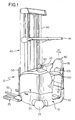
- Fig. 1 shows a rider reach truck 10 that includes a power unit 15 which houses a battery in the area indicated generally by the numeral 20 for supplying power to a traction motor (not shown) connected to a steerable wheel 25 located at the left rear corner of the power unit 15 and to hydraulic motors (not shown) which supply power to several different systems within the truck 10.
- a traction motor (not shown) connected to a steerable wheel 25 located at the left rear corner of the power unit 15 and to hydraulic motors (not shown) which supply power to several different systems within the truck 10.
- a caster wheel 30 is mounted at the right rear corner of the power unit 15.
- a pair of outriggers 35 support the front end of the truck 10.
- a mast assembly 40 mounted to the front of the truck 10 includes an overhead guard 45.
- a pair of forks 50 are carried on a fork carriage mechanism 55 which is carried on extendable mast elements 60.
- the fork carriage mechanism 55 may include a reach mechanism to allow the forks 50 to be extended forward of the mast assembly 40, a side shift mechanism to permit the forks 50 to be moved from side to side relative to the mast assembly 40, and a tilt mechanism to permit the forks 50 to be tilted relative to horizontal.
- the power unit 15 also includes an operator's compartment 70, also see Figs. 2 and 3, which defines an operator's station and in which is mounted a steering tiller 75 for controlling the direction of travel of the truck 10 and a control handle 80 for controlling the speed of travel and the forward and reverse direction of the truck 10 as well as fork height, fork extension, and fork tilt and side-shift.
- an operator's compartment 70 also see Figs. 2 and 3, which defines an operator's station and in which is mounted a steering tiller 75 for controlling the direction of travel of the truck 10 and a control handle 80 for controlling the speed of travel and the forward and reverse direction of the truck 10 as well as fork height, fork extension, and fork tilt and side-shift.
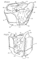
- the seat assembly 90 is mounted within the operator's compartment 70 which is attached to the right side of the power unit 15, as shown in Figs. 1-3.
- the seat assembly 90 includes a back rest 95, a seat 100, and a shelf 105 (or perch).
- the seat assembly 90 is vertically adjustable to accommodate operators having a range of heights.
- An armrest 110 is supported on the seat assembly 90 for movement therewith.
- the control handle 80 is mounted on an arm 115 extending from the armrest 110.
- pedals 120, 125 On the floor of the operator's compartment 70 are two pedals 120, 125.
- the left-hand pedal 120 operates an electric switch to control braking of the truck 10 and the right-hand pedal 125 operates an electric switch, the operation of which is required to operate the truck.
- a pedal 130 located within the operator's compartment are three additional pedals: a pedal 130, corresponding to the pedal 120; a pedal 135, corresponding to the pedal 125; and a pedal 140, which is an additional brake control pedal.
- the operator must have one foot on and depress either the pedal 120 or the pedal 130 in order for the vehicle to move; otherwise, the truck's brakes will be fully applied.
- the operator must also depress either the pedal 125 or the pedal 135 in order for the vehicle to move. If the operator removes a foot from the pedal 125 or the pedal 135 while the truck is moving, the truck will coast.
- the switches controlled by pedals 125 and 135 are known as power switches and indicate the presence of an operator within the operator's compartment 70.
- the pedal 140 operates an auxiliary brake switch so that anytime the operator depresses the pedal 140, the brakes of the truck will be immediately applied.
- the pedals 120, 130 will be referred to herein as "release to brake” pedals in accordance with their operation and the pedal 140 will be referred to herein as the "depress to brake" pedal.
- An operator's console 150 provides an operator of the truck 10 with information regarding the status of the battery voltage and may provide additional information regarding the fork height, the weight of the load on the forks, and other information to assist the operator of the truck 10.
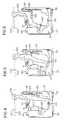
- Figs. 4, 5, and 6 illustrate the various positions an operator can assume during operation of the truck 10.
- Fig. 4 illustrates the operator standing position or the stand mode of operation
- Fig. 5 illustrates the operator perching position or the perch mode of operation
- Fig. 6 illustrates the operator seated or sit mode of operation.
- an operator 200 is shown standing, the seat 100 is lowered to be generally aligned with the back rest 95 and the shelf 105 is raised to be generally aligned with the back rest 95 such that the seat assembly 90 forms an operator cradling surface.
- the operator 200 is essentially presented with a contoured, cradling surface to support the back side of the operator's body providing a fifth point of operator stability for the operator in addition to the hand and feet controls.
- the operator's feet are generally placed on the floor pedals 120 and 125, as shown, to enable operation of the truck 10.
- the shelf 105 is extended or lowered to the position shown so that the shelf 105 is angularly oriented relative to the back rest 95 rather than being aligned with the back rest 95 as in Figs. 4 and 6. This allows the operator 200 to perch upon the lowered shelf 105 by resting his/her buttocks on or against the shelf 105 partially to support the weight of the body.
- the feet are normally moved slightly forward so that the operator's heels are usually placed on the floor mounted pedals 120 and 125.
- the seat 100 is placed in the raised position such that it is angularly oriented (generally perpendicular as illustrated) relative to the back rest 95, the shelf 105 is raised until it is flush with the back rest 95, and the operator's feet are resting on the pedals 130 and 135.
- the seat assembly 90 is adjustable vertically in order to place the seat assembly 90 at the vertical height that will ensure an appropriate and consistent eye level relative to the truck and the floor for each operator of the truck whether the operator is standing, perching or sitting.
- the dashed horizontal lines 204 and 206 in Figs. 4-6 show the limited extent of vertical movement of the operator's eyes, provided the seat assembly 90 is properly adjusted.
- the operator 200 shown in Figs. 4 and 5 may rest one foot on one of the floor mounted pedals 120 and 125, and the other foot on one of the elevated pedals 130, 135, and thus operate the truck 10 while changing position from time to time for variety and comfort.
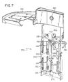
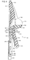
- the seat assembly 90 is mounted for limited vertical movement using the mechanism 230 shown in Figs. 7 and 8.
- a U-shaped member 235 is fixedly attached to the power unit 15 inside the operator's compartment 70.
- a movable member 240 nests within the bracket 235 and is provided with a set of vertically extending slots 245 which cooperate with a set of roller bearings 250 mounted on the member 235 to permit free vertical movement of the movable member 240 while preventing the member 240 from moving horizontally.
- a gas cylinder 260 is mounted on the member 240 by brackets 265 with a plunger 270 extending to a bracket 275 attached to the member 235.
- a valve 280 at the top of the cylinder 260 is controlled by an arm 290 pivotally attached to the member 240 at 295. Depressing the arm 290 allows the operator of the truck 10 to properly position the seat assembly 90 vertically for that operator. Once the arm 290 is released, the valve 280 closes and the seat assembly 90 remains in its selected vertical position.
- a pair of pivot points, or hinge members 300 are mounted at the upper portion of the member 240. These hinge members 300 support both the seat 100 and the shelf 105.
- An opening 310 is formed in the member 240.
- An extension 312 engages the opening 310 to act as a stop for the shelf 105 as shown in Fig. 101.
- a support member 320 for the back rest 95 Extending above and attached to the member 240 is a support member 320 for the back rest 95, and extending from the support member 320 is a support structure 330 for the arm rest 110. As shown in Fig. 8, a seat pan 340 is pivotally attached to the hinge members 300, as is a perch insert 350.
- the seat 100 is supported in its raised position shown in Fig. 10 by a centrally located seat cam latch 351 which is provided with an S-shaped slot that cooperates with a pin 355 and is mounted for pivotal movement about a pivot point 352.
- a seat cam latch release lever 360 moves a rod 365 that is pivotally attached to the latch 351 at 353 to release the seat 100, which may then be lowered to the position shown in Fig. 11.
- the seat 100 is raised and the release lever 360 is pulled such that the S-shaped slot in the cam latch 351 becomes disengaged from the pin 355 at which time the seat 100 can be lowered.
- the shelf 105 may be moved by the operator between its retracted or raised position shown in Figs. 1, 2, 4. 6 and 10 to its extended or lowered position shown in Figs. 5, 9 and 11.
- the back rest 95 includes a foam back pad 370 attached to member 320.
- the back pad is provided with a pair of wings 375 and includes a recess 380 to accommodate the shelf 105.
- the seat 100 similarly includes a foam pad 381 that surrounds the seat pan 340.
- the shelf 105 includes a foam pad 390 that surrounds the perch insert 350.
- the arm rest 110 also includes a foam pad 395 covering the support structure 330. It is noted that raising the seat 100 will cause the shelf 105 automatically to be raised and made substantially flush with the back rest 95.
Abstract
Description
Claims (11)
- An operator's station (70) for a materials handling vehicle (10) comprising:a seat assembly (90) comprising:a back rest (95);a seat (100) movable between a raised position adjacent to and angularly oriented relative to said back rest for seated operation of said vehicle and a lowered position for standing and perching operation of said vehicle, said back rest and said seat, when in said lowered position, forming an operator cradling surface; anda shelf (105) positioned between said back rest (95) and said seat (100), said shelf being movable between a raised position substantially aligned with said back rest for seated and standing operation of said vehicle and a lowered position angularly oriented relative to said back rest for perching operation of said vehicle.
- An operator's station (70) as claimed in claim 1 wherein said shelf (105) defines a portion of said back rest (95) when said shelf is in said raised position.
- An operator's station (70) as claimed in claim 1 wherein said operator's station includes a floor and further comprises:a first set of pedals (120, 125) on said floor; anda second set of pedals (130, 135) raised above said floor and positioned to be operated from said sitting position.
- An operator's station (70) as claimed in claim 3 wherein said first set of pedals (120,125) and said second set of pedals (130, 135) are both operable so that an operator (200) in said operator's station can operate one of said second set of pedals to provide flexibility of operating positions.
- An operator's station (70) as claimed in claim 3 wherein said first set of pedals (120. 125) comprises a release to brake pedal (120) and a power pedal (125).
- An operator's station (70) as claimed in claim 3 wherein said second set of pedals (130, 135) comprises a release to brake pedal (130) and a power pedal (135).
- An operator's station (70) as claimed in claim 6 wherein said second set of pedals further comprises a depress to brake pedal (140).
- An operator's station (70) for a materials handling vehicle (10), said operator's station including a floor and comprising:a first set of pedals on said floor (120, 125); anda second set of pedals (130,135) raised above said floor wherein said first set of pedals and said second set of pedals are both operable so that an operator (200) in said operator's station (70) can operate one of said second set of pedals to provide flexibility of operating positions.
- An operator's station (70) as claimed in claim 8 wherein said first set of pedals (120, 125) comprises a release to brake pedal (120) and a power pedal (125).
- An operator's station (70) as claimed in claim 8 wherein said second set of pedal (130, 135) comprises a release to brake pedal (130) and a power pedal (135).
- An operator's station (70) as claimed in claim 10 wherein said second set of pedals further comprises a depress to brake pedal (140).
Applications Claiming Priority (6)
| Application Number | Priority Date | Filing Date | Title |
|---|---|---|---|
| US5737597P | 1997-08-28 | 1997-08-28 | |
| US7375P | 1997-08-28 | ||
| US57375P | 1997-08-28 | ||
| US5810197P | 1997-09-05 | 1997-09-05 | |
| US58101P | 1997-09-05 | ||
| PCT/US1998/017688 WO1999010271A1 (en) | 1997-08-28 | 1998-08-26 | Operator's station for a lift truck including three position seat assembly |
Publications (2)
| Publication Number | Publication Date |
|---|---|
| EP1007463A1 EP1007463A1 (en) | 2000-06-14 |
| EP1007463B1 true EP1007463B1 (en) | 2002-01-09 |
Family
ID=26736409
Family Applications (1)
| Application Number | Title | Priority Date | Filing Date |
|---|---|---|---|
| EP98943404A Expired - Lifetime EP1007463B1 (en) | 1997-08-28 | 1998-08-26 | Operator's station for a lift truck including three position seat assembly |
Country Status (8)
| Country | Link |
|---|---|
| US (1) | US6189964B1 (en) |
| EP (1) | EP1007463B1 (en) |
| KR (1) | KR100567939B1 (en) |
| AT (1) | ATE211713T1 (en) |
| AU (1) | AU734492B2 (en) |
| CA (2) | CA2536345C (en) |
| DE (1) | DE69803469T2 (en) |
| NZ (1) | NZ516515A (en) |
Cited By (2)
| Publication number | Priority date | Publication date | Assignee | Title |
|---|---|---|---|---|
| US8388262B2 (en) | 2010-03-26 | 2013-03-05 | Bomag Gmbh | Operator workplace of a construction machine |
| CN106347327A (en) * | 2016-08-30 | 2017-01-25 | 宁波如意股份有限公司 | Pedal mechanism braking method |
Families Citing this family (52)
| Publication number | Priority date | Publication date | Assignee | Title |
|---|---|---|---|---|
| US6578919B2 (en) | 2001-05-15 | 2003-06-17 | Johnson Controls Technology Company | Vehicle seat |
| US6692076B1 (en) * | 2002-02-04 | 2004-02-17 | Peter J. Burer | Bolster chair with foldable seat that is vertically adjustable when folded into a vertical position |
| JP2003292298A (en) * | 2002-04-03 | 2003-10-15 | Toyota Industries Corp | Industrial vehicle |
| US7047716B2 (en) * | 2003-02-28 | 2006-05-23 | Deere & Company | Convertible support |
| US6871721B2 (en) * | 2003-06-03 | 2005-03-29 | The Raymond Corporation | Ergonomic operator compartment for operators of differing heights |
| US20050036880A1 (en) * | 2003-08-07 | 2005-02-17 | Magoto Daniel Carl | Pallet truck with reinforced fork weldment |
| ES2345819T3 (en) * | 2004-01-13 | 2010-10-04 | Moffett Research And Development Limited | LIFT TRUCK FOR MOUNTING ON THE REAR PART OF A TRANSPORT VEHICLE WITH ACCESSORY FOR LATERAL DISPLACEMENT OF THE FORK. |
| US7891457B2 (en) * | 2008-05-05 | 2011-02-22 | The Raymond Corporation | Vehicle having dual deadman pedals and method of operation |
| US7520567B2 (en) * | 2004-09-23 | 2009-04-21 | Crown Equipment Corporation | Systems and methods for seat repositioning |
| US7121608B2 (en) * | 2004-09-23 | 2006-10-17 | Crown Equipment Corporation | Rotating and/or swiveling seat |
| US7059680B2 (en) * | 2004-09-23 | 2006-06-13 | Crown Equipment Corporation | Seat repositioning device with release on control handle |
| AU2005222498B2 (en) * | 2004-10-12 | 2011-03-31 | Crown Equipment Corporation | Lift truck with heating system |
| US20060131941A1 (en) * | 2004-12-16 | 2006-06-22 | Hendron Scott S | Two way seat |
| US7726745B2 (en) * | 2005-10-27 | 2010-06-01 | Crown Equipment Corporation | Adjustable armrest mechanism for a materials handling vehicle |
| US7914078B2 (en) * | 2005-10-31 | 2011-03-29 | Deere & Company | Adjustable lower seat for use with a stand and lean type backrest |
| US7797918B2 (en) * | 2005-12-27 | 2010-09-21 | The Toro Company | Mower with flip up armrest carrying operational controls and display |
| CA2641314C (en) | 2006-02-03 | 2012-12-11 | Crown Equipment Corporation | Operator backrest and knee support pad for a materials handling vehicle |
| US7740259B2 (en) * | 2006-02-03 | 2010-06-22 | Crown Equipment Corporation | Movable step for a materials handling vehicle |
| DE102006015504A1 (en) * | 2006-03-31 | 2007-10-04 | Wirtgen Gmbh | Seat for a driver of a construction machine, as well as a construction machine |
| DE102006015979A1 (en) * | 2006-04-05 | 2007-10-11 | Jungheinrich Ag | Industrial truck, in particular high-shelf order picking truck |
| US7654602B2 (en) * | 2006-07-21 | 2010-02-02 | The Raymond Corporation | Reclining seat for a material handling vehicle |
| DE202007004984U1 (en) * | 2007-04-04 | 2007-06-06 | Jungheinrich Aktiengesellschaft | Forklift with operating platform, comprises outer body assembled of stationary and movable part |
| DE202007005756U1 (en) * | 2007-04-19 | 2008-08-28 | Wirtgen Gmbh | Self-propelled construction machine |
| CA2683477A1 (en) * | 2008-10-29 | 2010-04-29 | The Raymond Corporation | Vehicle seat assembly |
| US20100283300A1 (en) * | 2009-05-06 | 2010-11-11 | Gryp Dennis J | Vehicle seat apparatus |
| US8172312B2 (en) * | 2009-09-03 | 2012-05-08 | Caterpillar Global Mining Llc | Excavator cab with an improved field of view |
| DE102011018801A1 (en) * | 2011-04-27 | 2012-10-31 | Still Gmbh | Industrial truck with a driver's seat forming a sitting and standing aid |
| DE102011117180B4 (en) * | 2011-10-28 | 2021-01-14 | Volkswagen Aktiengesellschaft | Control element arrangement for controlling a vehicle in combination with a convertible vehicle seat |
| GB201204387D0 (en) * | 2012-03-12 | 2012-04-25 | Translift Bendi Ltd | Order pickers |
| US9035208B2 (en) | 2012-12-27 | 2015-05-19 | The Raymond Corporation | Control module with redundant switches |
| US8905183B2 (en) | 2013-03-14 | 2014-12-09 | The Raymond Corporation | Contoured backrest with integrated control module for use with a material handling vehicle |
| DE102013209532B4 (en) * | 2013-05-23 | 2018-04-26 | Siemens Aktiengesellschaft | seating device |
| US9192530B2 (en) | 2013-07-29 | 2015-11-24 | Nacco Materials Handling Group, Inc. | Moveable seat |
| US9205879B2 (en) * | 2014-04-15 | 2015-12-08 | Hasani Nnamdi Ephraim | Stand up sit down (SUSD) vehicle's |
| US10023447B2 (en) | 2014-05-28 | 2018-07-17 | Harlan Greenfield | Wheelchair accessible forklift |
| JP5909268B1 (en) * | 2014-09-30 | 2016-04-26 | 三菱重工業株式会社 | Backrest, vehicle, and guided track traffic system |
| DE102014114428A1 (en) * | 2014-10-06 | 2016-04-07 | Jungheinrich Aktiengesellschaft | Industrial truck with a stand |
| CN104477823A (en) * | 2014-12-10 | 2015-04-01 | 苏州先锋物流装备科技有限公司 | Dual-purpose forklift with vertical seat |
| JP1556401S (en) * | 2016-01-08 | 2016-08-15 | ||
| CN106080311A (en) * | 2016-06-16 | 2016-11-09 | 苏州先锋物流装备科技有限公司 | A kind of separate type backrest seat |
| JP1615679S (en) * | 2017-11-22 | 2019-10-07 | ||
| JP1612267S (en) * | 2017-11-22 | 2021-08-23 | ||
| JP1612268S (en) * | 2017-11-22 | 2021-08-23 | ||
| JP1612266S (en) * | 2017-11-22 | 2021-08-23 | ||
| CN108146306B (en) * | 2018-02-02 | 2023-10-03 | 江苏昊邦智能控制系统股份有限公司 | Folding lightning-proof car seat for military car |
| USD920388S1 (en) * | 2019-04-30 | 2021-05-25 | Spohn & Burkhardt GmbH & Co. KG | Control unit |
| EP4114784A1 (en) | 2020-03-06 | 2023-01-11 | Oshkosh Corporation | Lift device with deployable operator station |
| JP2023550474A (en) * | 2020-11-23 | 2023-12-01 | アレン リーブス、デイビッド | Foot-controlled stand-up zero-turn utility vehicle |
| US20220379781A1 (en) * | 2021-03-12 | 2022-12-01 | Mtd Products Inc | Outdoor power equipment with converter seated and standing operator positions |
| US11667321B2 (en) | 2021-09-30 | 2023-06-06 | Ford Global Technologies, Llc | Interior system of a vehicle |
| US11613295B1 (en) | 2021-09-30 | 2023-03-28 | Ford Global Technologies, Llc | Interior system of a vehicle |
| CN114379435A (en) * | 2022-02-14 | 2022-04-22 | 伍洪少 | Bus and truck capable of being driven in standing mode |
Family Cites Families (10)
| Publication number | Priority date | Publication date | Assignee | Title |
|---|---|---|---|---|
| ZA866246B (en) | 1985-08-27 | 1987-04-29 | Mim Holdings Ltd | Bi-directional vehicle control station |
| US5044472A (en) * | 1989-12-05 | 1991-09-03 | Crown Equipment Corporation | Dual operator position for material handling vehicle |
| GB2249287B (en) * | 1990-11-01 | 1994-09-14 | Nicholas Ewart Edmund | Wheelchair |
| US5364151A (en) * | 1993-04-21 | 1994-11-15 | Mack Trucks, Inc. | Adjustable seat apparatus for utility vehicle |
| WO1995001889A1 (en) | 1993-07-06 | 1995-01-19 | Dmitry Alexandrovich Shevtsov | Convertible seat |
| DE4409917C2 (en) * | 1994-03-23 | 1997-07-10 | Porsche Ag | Support device |
| GB2289669B (en) * | 1994-05-20 | 1997-12-17 | Lansing Linde Ltd | Industrial lift trucks |
| DE4437568C1 (en) | 1994-09-29 | 1996-01-04 | Wagner Foerdertechnik | Fork-lift truck |
| DE4434908C1 (en) | 1994-09-29 | 1996-03-21 | Wagner Foerdertechnik | Floor conveyor vehicle with driving seat, esp. high lift stacker |
| US5688025A (en) * | 1995-01-17 | 1997-11-18 | Davidson; Timothy H. | Two level convertible child car seat |
-
1998
- 1998-08-26 KR KR1020007001793A patent/KR100567939B1/en not_active IP Right Cessation
- 1998-08-26 AT AT98943404T patent/ATE211713T1/en not_active IP Right Cessation
- 1998-08-26 EP EP98943404A patent/EP1007463B1/en not_active Expired - Lifetime
- 1998-08-26 NZ NZ516515A patent/NZ516515A/en not_active IP Right Cessation
- 1998-08-26 AU AU91211/98A patent/AU734492B2/en not_active Expired
- 1998-08-26 CA CA002536345A patent/CA2536345C/en not_active Expired - Lifetime
- 1998-08-26 DE DE69803469T patent/DE69803469T2/en not_active Expired - Lifetime
- 1998-08-26 CA CA002296617A patent/CA2296617C/en not_active Expired - Lifetime
- 1998-08-27 US US09/141,085 patent/US6189964B1/en not_active Expired - Lifetime
Cited By (3)
| Publication number | Priority date | Publication date | Assignee | Title |
|---|---|---|---|---|
| US8388262B2 (en) | 2010-03-26 | 2013-03-05 | Bomag Gmbh | Operator workplace of a construction machine |
| CN106347327A (en) * | 2016-08-30 | 2017-01-25 | 宁波如意股份有限公司 | Pedal mechanism braking method |
| CN106347327B (en) * | 2016-08-30 | 2019-01-25 | 宁波如意股份有限公司 | A kind of braking method of pedal gear |
Also Published As
| Publication number | Publication date |
|---|---|
| ATE211713T1 (en) | 2002-01-15 |
| CA2536345C (en) | 2008-01-08 |
| CA2296617C (en) | 2006-12-19 |
| AU9121198A (en) | 1999-03-16 |
| DE69803469D1 (en) | 2002-02-28 |
| EP1007463A1 (en) | 2000-06-14 |
| NZ516515A (en) | 2003-08-29 |
| CA2296617A1 (en) | 1999-03-04 |
| KR20010023167A (en) | 2001-03-26 |
| CA2536345A1 (en) | 1999-03-04 |
| AU734492B2 (en) | 2001-06-14 |
| KR100567939B1 (en) | 2006-04-07 |
| US6189964B1 (en) | 2001-02-20 |
| DE69803469T2 (en) | 2002-09-12 |
Similar Documents
| Publication | Publication Date | Title |
|---|---|---|
| EP1007463B1 (en) | Operator's station for a lift truck including three position seat assembly | |
| CA2302051C (en) | Materials handling vehicle having an expanded operator's compartment | |
| US5984338A (en) | Lightweight stabilized raising chair | |
| JPH053080Y2 (en) | ||
| CA2657924C (en) | Reclining seat for a material handling vehicle | |
| WO1999010271A1 (en) | Operator's station for a lift truck including three position seat assembly | |
| EP0555025B1 (en) | An integrated controls and seating configuration for reach-fork vehicles | |
| JP2002193018A (en) | Footrest device | |
| US4598948A (en) | Vehicle armrest support | |
| US5839542A (en) | Industrial truck with an operating console | |
| AU751176B2 (en) | Operator's station for a lift truck | |
| JP2005132525A (en) | Backrest structure for standing ride type driver's platform in industrial vehicle | |
| CN108652840A (en) | Motor vehicles with mobile vehicle seat | |
| WO2018091907A1 (en) | Seat adjustment mechanism | |
| MXPA00001830A (en) | Materials handling vehicle having an expanded operator's compartment | |
| US20100033003A1 (en) | Sit/stand support for a vehicle | |
| JPH0454757Y2 (en) | ||
| JP2502454Y2 (en) | Chair with reclining device | |
| JPH0722259Y2 (en) | Seat slide device for electric vehicle | |
| JPH09328027A (en) | Tilt angle adjusting device for industrial vehicle seat | |
| JP2011063197A (en) | Driving position adjusting apparatus for vehicle | |
| JPH07323047A (en) | Electric chair |
Legal Events
| Date | Code | Title | Description |
|---|---|---|---|
| PUAI | Public reference made under article 153(3) epc to a published international application that has entered the european phase |
Free format text: ORIGINAL CODE: 0009012 |
|
| 17P | Request for examination filed |
Effective date: 20000327 |
|
| AK | Designated contracting states |
Kind code of ref document: A1 Designated state(s): AT BE CH CY DE DK ES FI FR GB GR IE IT LI LU MC NL PT SE |
|
| GRAG | Despatch of communication of intention to grant |
Free format text: ORIGINAL CODE: EPIDOS AGRA |
|
| 17Q | First examination report despatched |
Effective date: 20010301 |
|
| GRAG | Despatch of communication of intention to grant |
Free format text: ORIGINAL CODE: EPIDOS AGRA |
|
| GRAH | Despatch of communication of intention to grant a patent |
Free format text: ORIGINAL CODE: EPIDOS IGRA |
|
| GRAH | Despatch of communication of intention to grant a patent |
Free format text: ORIGINAL CODE: EPIDOS IGRA |
|
| GRAA | (expected) grant |
Free format text: ORIGINAL CODE: 0009210 |
|
| REG | Reference to a national code |
Ref country code: GB Ref legal event code: IF02 |
|
| AK | Designated contracting states |
Kind code of ref document: B1 Designated state(s): AT BE CH CY DE DK ES FI FR GB GR IE IT LI LU MC NL PT SE |
|
| PG25 | Lapsed in a contracting state [announced via postgrant information from national office to epo] |
Ref country code: NL Free format text: LAPSE BECAUSE OF FAILURE TO SUBMIT A TRANSLATION OF THE DESCRIPTION OR TO PAY THE FEE WITHIN THE PRESCRIBED TIME-LIMIT Effective date: 20020109 Ref country code: LI Free format text: LAPSE BECAUSE OF FAILURE TO SUBMIT A TRANSLATION OF THE DESCRIPTION OR TO PAY THE FEE WITHIN THE PRESCRIBED TIME-LIMIT Effective date: 20020109 Ref country code: IT Free format text: LAPSE BECAUSE OF FAILURE TO SUBMIT A TRANSLATION OF THE DESCRIPTION OR TO PAY THE FEE WITHIN THE PRESCRIBED TIME-LIMIT;WARNING: LAPSES OF ITALIAN PATENTS WITH EFFECTIVE DATE BEFORE 2007 MAY HAVE OCCURRED AT ANY TIME BEFORE 2007. THE CORRECT EFFECTIVE DATE MAY BE DIFFERENT FROM THE ONE RECORDED. Effective date: 20020109 Ref country code: GR Free format text: LAPSE BECAUSE OF FAILURE TO SUBMIT A TRANSLATION OF THE DESCRIPTION OR TO PAY THE FEE WITHIN THE PRESCRIBED TIME-LIMIT Effective date: 20020109 Ref country code: FI Free format text: LAPSE BECAUSE OF FAILURE TO SUBMIT A TRANSLATION OF THE DESCRIPTION OR TO PAY THE FEE WITHIN THE PRESCRIBED TIME-LIMIT Effective date: 20020109 Ref country code: CH Free format text: LAPSE BECAUSE OF FAILURE TO SUBMIT A TRANSLATION OF THE DESCRIPTION OR TO PAY THE FEE WITHIN THE PRESCRIBED TIME-LIMIT Effective date: 20020109 Ref country code: BE Free format text: LAPSE BECAUSE OF FAILURE TO SUBMIT A TRANSLATION OF THE DESCRIPTION OR TO PAY THE FEE WITHIN THE PRESCRIBED TIME-LIMIT Effective date: 20020109 Ref country code: AT Free format text: LAPSE BECAUSE OF FAILURE TO SUBMIT A TRANSLATION OF THE DESCRIPTION OR TO PAY THE FEE WITHIN THE PRESCRIBED TIME-LIMIT Effective date: 20020109 |
|
| REF | Corresponds to: |
Ref document number: 211713 Country of ref document: AT Date of ref document: 20020115 Kind code of ref document: T |
|
| REG | Reference to a national code |
Ref country code: CH Ref legal event code: EP |
|
| REG | Reference to a national code |
Ref country code: IE Ref legal event code: FG4D |
|
| REF | Corresponds to: |
Ref document number: 69803469 Country of ref document: DE Date of ref document: 20020228 |
|
| PG25 | Lapsed in a contracting state [announced via postgrant information from national office to epo] |
Ref country code: SE Free format text: LAPSE BECAUSE OF FAILURE TO SUBMIT A TRANSLATION OF THE DESCRIPTION OR TO PAY THE FEE WITHIN THE PRESCRIBED TIME-LIMIT Effective date: 20020409 Ref country code: PT Free format text: LAPSE BECAUSE OF FAILURE TO SUBMIT A TRANSLATION OF THE DESCRIPTION OR TO PAY THE FEE WITHIN THE PRESCRIBED TIME-LIMIT Effective date: 20020409 Ref country code: DK Free format text: LAPSE BECAUSE OF FAILURE TO SUBMIT A TRANSLATION OF THE DESCRIPTION OR TO PAY THE FEE WITHIN THE PRESCRIBED TIME-LIMIT Effective date: 20020409 |
|
| NLV1 | Nl: lapsed or annulled due to failure to fulfill the requirements of art. 29p and 29m of the patents act | ||
| REG | Reference to a national code |
Ref country code: CH Ref legal event code: PL |
|
| PG25 | Lapsed in a contracting state [announced via postgrant information from national office to epo] |
Ref country code: ES Free format text: LAPSE BECAUSE OF FAILURE TO SUBMIT A TRANSLATION OF THE DESCRIPTION OR TO PAY THE FEE WITHIN THE PRESCRIBED TIME-LIMIT Effective date: 20020730 |
|
| PG25 | Lapsed in a contracting state [announced via postgrant information from national office to epo] |
Ref country code: LU Free format text: LAPSE BECAUSE OF NON-PAYMENT OF DUE FEES Effective date: 20020826 Ref country code: IE Free format text: LAPSE BECAUSE OF NON-PAYMENT OF DUE FEES Effective date: 20020826 |
|
| PG25 | Lapsed in a contracting state [announced via postgrant information from national office to epo] |
Ref country code: CY Free format text: LAPSE BECAUSE OF FAILURE TO SUBMIT A TRANSLATION OF THE DESCRIPTION OR TO PAY THE FEE WITHIN THE PRESCRIBED TIME-LIMIT Effective date: 20020831 |
|
| PLBE | No opposition filed within time limit |
Free format text: ORIGINAL CODE: 0009261 |
|
| STAA | Information on the status of an ep patent application or granted ep patent |
Free format text: STATUS: NO OPPOSITION FILED WITHIN TIME LIMIT |
|
| 26N | No opposition filed | ||
| PG25 | Lapsed in a contracting state [announced via postgrant information from national office to epo] |
Ref country code: MC Free format text: LAPSE BECAUSE OF NON-PAYMENT OF DUE FEES Effective date: 20030301 |
|
| REG | Reference to a national code |
Ref country code: IE Ref legal event code: MM4A |
|
| NLV1 | Nl: lapsed or annulled due to failure to fulfill the requirements of art. 29p and 29m of the patents act | ||
| REG | Reference to a national code |
Ref country code: FR Ref legal event code: PLFP Year of fee payment: 19 |
|
| REG | Reference to a national code |
Ref country code: FR Ref legal event code: PLFP Year of fee payment: 20 |
|
| PGFP | Annual fee paid to national office [announced via postgrant information from national office to epo] |
Ref country code: FR Payment date: 20170822 Year of fee payment: 20 Ref country code: DE Payment date: 20170822 Year of fee payment: 20 Ref country code: GB Payment date: 20170822 Year of fee payment: 20 |
|
| REG | Reference to a national code |
Ref country code: DE Ref legal event code: R071 Ref document number: 69803469 Country of ref document: DE |
|
| REG | Reference to a national code |
Ref country code: GB Ref legal event code: PE20 Expiry date: 20180825 |
|
| PG25 | Lapsed in a contracting state [announced via postgrant information from national office to epo] |
Ref country code: GB Free format text: LAPSE BECAUSE OF EXPIRATION OF PROTECTION Effective date: 20180825 |
|
| P01 | Opt-out of the competence of the unified patent court (upc) registered |
Effective date: 20230529 |