EP1007451B1 - Vibratory conveyor apparatus with phase-optimized conveyor drive - Google Patents
Vibratory conveyor apparatus with phase-optimized conveyor drive Download PDFInfo
- Publication number
- EP1007451B1 EP1007451B1 EP98901725A EP98901725A EP1007451B1 EP 1007451 B1 EP1007451 B1 EP 1007451B1 EP 98901725 A EP98901725 A EP 98901725A EP 98901725 A EP98901725 A EP 98901725A EP 1007451 B1 EP1007451 B1 EP 1007451B1
- Authority
- EP
- European Patent Office
- Prior art keywords
- vibratory
- drive shafts
- drive
- line
- along
- Prior art date
- Legal status (The legal status is an assumption and is not a legal conclusion. Google has not performed a legal analysis and makes no representation as to the accuracy of the status listed.)
- Expired - Lifetime
Links
- 230000033001 locomotion Effects 0.000 claims description 25
- 230000001360 synchronised effect Effects 0.000 claims description 4
- 230000001939 inductive effect Effects 0.000 claims description 3
- 239000000463 material Substances 0.000 description 18
- 230000000694 effects Effects 0.000 description 6
- 238000002955 isolation Methods 0.000 description 4
- 230000001965 increasing effect Effects 0.000 description 3
- 230000004048 modification Effects 0.000 description 2
- 238000012986 modification Methods 0.000 description 2
- 244000208734 Pisonia aculeata Species 0.000 description 1
- 230000000996 additive effect Effects 0.000 description 1
- 235000013339 cereals Nutrition 0.000 description 1
- 238000010276 construction Methods 0.000 description 1
- 235000013606 potato chips Nutrition 0.000 description 1
Images


Classifications
-
- B—PERFORMING OPERATIONS; TRANSPORTING
- B65—CONVEYING; PACKING; STORING; HANDLING THIN OR FILAMENTARY MATERIAL
- B65G—TRANSPORT OR STORAGE DEVICES, e.g. CONVEYORS FOR LOADING OR TIPPING, SHOP CONVEYOR SYSTEMS OR PNEUMATIC TUBE CONVEYORS
- B65G27/00—Jigging conveyors
- B65G27/10—Applications of devices for generating or transmitting jigging movements
- B65G27/16—Applications of devices for generating or transmitting jigging movements of vibrators, i.e. devices for producing movements of high frequency and small amplitude
- B65G27/18—Mechanical devices
- B65G27/20—Mechanical devices rotating unbalanced masses
-
- B—PERFORMING OPERATIONS; TRANSPORTING
- B06—GENERATING OR TRANSMITTING MECHANICAL VIBRATIONS IN GENERAL
- B06B—METHODS OR APPARATUS FOR GENERATING OR TRANSMITTING MECHANICAL VIBRATIONS OF INFRASONIC, SONIC, OR ULTRASONIC FREQUENCY, e.g. FOR PERFORMING MECHANICAL WORK IN GENERAL
- B06B1/00—Methods or apparatus for generating mechanical vibrations of infrasonic, sonic, or ultrasonic frequency
- B06B1/10—Methods or apparatus for generating mechanical vibrations of infrasonic, sonic, or ultrasonic frequency making use of mechanical energy
- B06B1/16—Methods or apparatus for generating mechanical vibrations of infrasonic, sonic, or ultrasonic frequency making use of mechanical energy operating with systems involving rotary unbalanced masses
- B06B1/161—Adjustable systems, i.e. where amplitude or direction of frequency of vibration can be varied
- B06B1/166—Where the phase-angle of masses mounted on counter-rotating shafts can be varied, e.g. variation of the vibration phase
-
- B—PERFORMING OPERATIONS; TRANSPORTING
- B65—CONVEYING; PACKING; STORING; HANDLING THIN OR FILAMENTARY MATERIAL
- B65G—TRANSPORT OR STORAGE DEVICES, e.g. CONVEYORS FOR LOADING OR TIPPING, SHOP CONVEYOR SYSTEMS OR PNEUMATIC TUBE CONVEYORS
- B65G27/00—Jigging conveyors
- B65G27/10—Applications of devices for generating or transmitting jigging movements
- B65G27/28—Applications of devices for generating or transmitting jigging movements with provision for dynamic balancing
- B65G27/30—Applications of devices for generating or transmitting jigging movements with provision for dynamic balancing by means of an oppositely-moving mass, e.g. a second conveyor
Definitions
- the present invention relates generally to a vibratory conveyor apparatus, and more particularly to a conveyor apparatus having an improved differential motion vibratory drive with eccentric weights of the drive mounted in a phase-optimized configuration for increasing the velocity of material conveyed by the apparatus.
- Vibratory conveyors are widely used for material handling, and typically include a generally elongated conveyor bed, and an associated vibratory drive. Operation of the vibratory drive induces vibratory motion in the conveyor bed, which motion in turn induces movement of articles along the bed.
- Vibratory drives for such devices typically include one or more pairs of counter-rotating shafts having eccentrically-mounted weights thereon for inducing the desired vibration of the conveyor bed.
- One type of vibratory conveyor arrangement sometimes referred to as a four shaft differential motion conveyor, includes a vibratory drive including first and second pairs of counter-rotating drive shafts. with one pair of drive shafts operated at twice the speed of the second pair.
- This type of vibratory drive arrangement has been found to induce substantially planar, slow forward and fast rearward motion, which is well suited for gentle handling of delicate materials, such as potato chips. flaked cereals, and the like.
- the vibratory drive is configured such that the half-speed and full-speed drive shafts are synchronized, or operated in phase, such that the vibratory forces induced by the eccentrically mounted weights cyclically add in one direction, and cyclically subtract in the other direction.
- the drive is configured such that the addition of vibratory forces acts in the direction opposite to the material flow, causing a fast pull-back of the conveyor bed.
- the vibratory forces subtract from one another in the direction of material flow, thereby causing the vibratory bed to slowly move forward in the direction of material feed.
- a vibratory conveyor is described with two pairs of drive shafts on which two different sets of eccentric weights are mounted.
- the shafts of the first set of eccentric weights are driven at double speed compared to the shafts of the second set of weights.
- the weights of the first and second set are each mounted on the drive shaft in the same direction whereby the first set of weights is orientated on their drive shafts in an angle a compared to the second set of weights. Accordingly, the maximum vibratory forces of the first and second set of eccentrically mounted weights occur in-phase to one another.
- the present invention contemplates an arrangement whereby eccentric weights of a differential motion vibratory drive are configured to provide out-of-phase inducement of vibratory motions, thereby substantially increasing the feed rate of material being conveyed, without any change in the rotating and balance of the shafts of the drive.
- a vibratory conveyor apparatus, and vibratory conveyor drive, embodying the principles of the present invention includes first and second pairs of counter-rotating drive shafts upon which first and second eccentric weight sets are respectively mounted.
- the eccentric weights of the present vibratory drive are arranged such that vibratory forces induced by the first set of weights are out-of-phase with the vibratory motion induced by the second eccentric weight set.
- the second weight set being mounted to induce maximum values of reciprocable vibratory forces along a line perpendicular to the plane defined by the second drive shafts whereby the first eccentric weight set being mounted to induce maximum values of first reciprocable vibratory forces along a line perpendicular to the plane defined by the first drive shafts, the maximum values of the first reciprocable vibratory forces being out-of-phase with the maximum values of the second reciprocable vibratory forces.
- the net effect of this phase optimized configuration of the eccentric weights is a substantial increase in the feed rate of the conveyor (on the order of fifty percent) for the same rotating imbalance on the drive shafts when compared to a conventional vibratory drive.
- the same material flow rate can be achieved as in a non-optimized system, thereby permitting reduction in drive connection strength, bearing and shaft sizes, etc., thus permitting the present arrangement to be more economically manufactured than previous constructions.
- a vibratory conveyor apparatus embodying the principles of the present invention includes an elongated conveyor bed, and a vibratory conveyor drive attached to the conveyor bed for inducing vibratory motion in the bed.
- the induced vibratory motion of the conveyor bed thereby effects conveyance of articles in a conveying direction along the length of the bed.
- the vibratory drive comprises a frame, and first and second parallel pairs of counter-rotating drive shafts rotatably mounted on the frame.
- a drive arrangement illustrated as including an electric motor and a system of drive belts, effects conjoint rotation of the first and second counter-rotating drive shafts, with the drive arrangement preferably configured to effect differential motion of the first and second pairs of shafts by rotation of the first pair of shafts at twice the rotational speed as the second pair of counter-rotating shafts.
- the present vibratory drive further includes first and second eccentric weight sets respectively mounted on the first and second pairs of counter-rotating shafts.
- the first weight set includes at least one eccentric weight mounted on each of the first pair of drive shafts for rotation therewith, with the second weight set similarly including at least one eccentric weight mounted on each of the second pair of drive shafts for rotation therewith.
- the first eccentric weight set is eccentrically mounted to induce first reciprocable vibratory forces which are out-of-phase with second reciprocable vibratory forces induced by the second eccentric weight set. It is preferred that the first and second sets of eccentric weights are mounted on the first and second pairs of drive shafts to induce reciprocable vibratory forces along a line substantially parallel to the conveying direction of the conveyor apparatus.
- the first vibratory forces induced along this line are out-of-phase with the second vibratory forces in that the maximum values of the first vibratory forces along the line are non-synchronous with the maximum values of the second vibratory forces along the line.
- the first and second eccentric weight sets are mounted such that the maximum values of the first vibratory forces are induced along the line at 45 degrees of rotation of the first drive shafts after maximum and minimum values of the second vibratory forces are induced along the line.
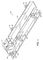
- FIGURE 1 With reference first to FIGURE 1, therein is illustrated a vibratory conveyor apparatus 10 embodying the principles of the present invention.
- the conveyor apparatus 10 includes a generally elongated conveyor bed 12 along which material to be conveyed is carried, generally in the direction indicated by the arrow C shown in FIGURE 1.
- a vibratory drive 14, embodying the principles of the present invention, is attached to the conveyor bed 12 whereby operation of the vibratory drive induces vibratory motion in the conveyor bed along a line substantially parallel to the conveying direction of material moving along the conveyor bed.
- the conveyor bed 12 and the vibratory drive 14 are mounted on a series of isolation supports 16 each including one or more isolation rocker legs 18 which suspend the conveyor bed and drive from isolation A-frames 20.
- the rocker legs 18 are typically connected with the A-frames, the conveyor bed 12, and the associated drive 14 with suitable bolts or other mechanical fasteners extending through rubber bushings press-fitted into opposite ends of the rocker legs 18.
- This arrangement allows the conveyor bed and drive to move smoothly forward and backward along a pendular arc.
- the isolation mounting arrangement effects mounting of the conveyor bed and vibratory drive for pendular arcuate movement.
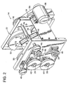
- the vibratory drive 14 is sometimes referred to as a four shaft differential motion drive, in that it includes first and second pairs of counter-rotating drive shafts, wherein the first pair of drive shafts are driven at twice the rotational speed of the second pair of drive shafts.
- the vibratory drive 14 includes a frame 22 with a first pair of counter-rotating drive shafts 24, and a second pair of counter-rotating drive shafts 26 rotatably mounted in the frame 22.
- the first and second pairs of shafts are parallel to each other, with the first shafts 24 mounted in vertically aligned relationship, and the second shafts 26 also mounted in vertically aligned relationship, and in laterally spaced relationship to the first shafts 24.
- Suitable bearings provide the desired rotatable mounting of the drive shafts 24 and 26.
- a drive motor 28 preferably comprising an electric motor, operates through the primary drive belt 30 to effect driven rotation of the upper one of drive shafts 24 via a drive input sheave 32.
- An idler 34 which may be configured as a Lovejoy idler, maintains the desired tension in the drive belt 30.
- first drive shafts 24 are rotatably driven at twice the rotational speed of second drive shafts 26.
- the vibratory drive 14 includes first and second eccentric weight sets respectively mounted on the first and second pairs of counter-rotating drive shafts.
- the first weight set includes at least one eccentric weight mounted on each of first drive shafts 24, with the illustrated embodiment including two first eccentric weights 46 mounted on the upper one of drive shafts 24, generally at the center thereof, and two first eccentric weights 48 mounted on the lower one of drive shafts 24, generally at respective opposite ends thereof.
- the second eccentric weight set includes at least one weight mounted on each of the second drive shafts 26.
- a pair of second eccentric weights 50 are mounted on the upper one of second drive shafts 26, generally at respective opposite ends thereof, with a pair of second eccentric weights 52 mounted on the lower one of second drive shafts 26, generally at the center thereof. While the specific weight of each of the first and second weights can be varied while keeping with the principles disclosed herein, in a presently preferred embodiment, the first weight set collectively weighs less than the second weight set. In the illustrated embodiment, each of the four second weights 50, 52 weighs approximately three times each of the four first weights 46, 48.
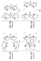
- FIGURES 5A-D and 6A-D the optimized arrangement of the eccentric weights 46, 48, and 50, 52 is diagrammatically illustrated, in comparison to a typical four shaft differential motion vibratory drive (with arrows illustrating the direction of material conveyance on the associated conveyor bed 12).
- a conventional drive is configured such that the eccentric weights, designated W 1 and W 2 , of the first and second pairs of counter-rotating shafts (wherein the first shafts rotate at twice the speed of the second shafts) provide a generally additive effect, that is, the maximum values of the vibratory motions induced by the weights are in phase and synchronized with each other.
- FIGURE 6A-D shows the configuration of the eccentric weights of the present vibratory drive, which are mounted in an out-of-phase arrangement so that the maximum values of the vibratory forces of the first eccentric weight set are induced along a line (extending perpendicular to a plane through the first drive shafts) out-of-phase with the maximum values of the vibratory forces created along the line by the second weight set.
- the maximum values of the first vibratory forces are induced along the line out-of-phase with the maximum values of the second vibratory forces, with a presently preferred arrangement configured such that the first and second weight sets are mounted so that the maximum values of the first vibratory forces are induced along the line at 45 degrees of rotation of the first drive shafts after maximum and minimum values of the second vibratory forces are induced along the line.
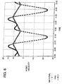
- FIGURES 7 and 8 graphically illustrate and compare the theoretical motion of the vibratory conveyor bed 12, and material carried thereon.
- FIGURE 7 illustrates the motion of the bed, and conveyed material, as provided by a conventional four shaft differential motion vibratory drive, as diagrammatically shown in FIGURE 5A-D.
- FIGURE 8 illustrates graphically the motion of the conveyor bed 12, and material conveyed thereon, as driven by the vibratory drive 14 embodying the principles of the present invention.
- substantially increased material feed rates are achieved by the vibratory drive configured in accordance with the present invention.
- the above-described configuration of the first and second weight sets of the vibratory drive 14 are configured such that the first weight set, including weights 46, 48, induce first reciprocable vibratory forces along the line perpendicular to a plane extending through the first drive shafts 24, 24, with maximum values of the first vibratory forces being cyclically induced in opposite directions along the line attendant to each rotation of the counter-rotating first drive shafts.
- the weights 50, 52 of the second weight set are mounted on the second pair of drive shafts 26, 26 to induce second reciprocable vibratory forces along the aforesaid line, with maximum values of the second vibratory forces being cyclically induced in opposite directions along the line attendant to each rotation of the counter-rotating second drive shafts 26, 26.
- first and second eccentric weight sets are mounted so that maximum values of the first vibratory forces are induced along the aforesaid line at 45 degrees of rotation of the first drive shafts 24 after maximum and minimum values of the second vibratory forces are induced along the line.
- the eccentric weight sets can be positioned in an out-of-phase relationship other than at this specific angular orientation.
Landscapes
- Engineering & Computer Science (AREA)
- Mechanical Engineering (AREA)
- Jigging Conveyors (AREA)
Description
Claims (11)
- A vibratory conveyor apparatus comprising:characterized in thatan elongated conveyor bed (12) and a vibratory conveyor drive (14) attached to said conveyor bed (12) for inducing vibratory motion in said conveyor bed (12) for thereby effecting conveyance of articles in a conveying direction along said bed (12), said vibrating drive (14) comprising a frame (22), first and second pairs of counter-rotating drive shafts (24, 26) rotatably mounted on said frame, and means (28, 30, 36) for rotatably driving said drive shafts (24, 26), said vibrating drive (14) further including first and second eccentric weight sets (46, 48, 50, 52), said first eccentric weight set including at least one eccentric weight (46, 48) mounted on each of said first pair of drive shafts (24) for rotation therewith, and said second weight set including at least one eccentric weight (50, 52) mounted on each of said second pair of drive shafts (26) for rotation therewith, the plane defined by the first pair of drive shafts (24) being parallel to the plane defined by the second pair of drive shafts (26), said first eccentric weight set (46, 48) being mounted to induce maximum values of first reciprocable vibratory forces along a line perpendicular to the plane defined by the first drive shafts (24), said second eccentric weight set (50, 52) being mounted to induce maximum values of second reciprocable vibratory forces along a line perpendicular to the plane defined by the second drive shafts (26),
the first eccentric weight set (46, 48) is arranged so that the maximum values of the first reciprocable vibratory forces induced along said line are out-of-phase with the maximum values of the second reciprocable vibratory forces induced along said line. - A vibratory conveyor apparatus in accordance with claim 1, wherein said means (28, 30, 36) for rotatably driving said drive shafts (24, 26) drive said first pair of drive shafts (24) at twice the rotational speed of said second pair of drive shafts (26).
- A vibratory conveyor apparatus in accordance with claim 1, wherein said first and second sets of eccentric weights (46, 48, 50, 52) are respectively mounted on said first and second pairs of drive shafts (24, 26) to induce reciprocable vibratory forces along a line substantially parallel to said conveying direction, said first vibratory forced induced along said line by said first weight set (46, 48) being out-of-phase with the second vibratory forces induced by said second weight set (50, 52) by the maximum value of said first vibratory forces along said line being non-synchronous with the maximum value of said second vibratory forces along said line.
- A vibratory conveyor apparatus in accordance with claim 1, wherein said first pair of drive shafts (24) are mounted in parallel, vertically aligned relationship on said frame (22), and said second pair of drive shafts (26) are mounted in parallel, vertically aligned relationship on said frame (22) and in laterally spaced relationship to said first drive shafts (24).
- A vibratory conveyor apparatus in accordance with claim 1, including means for mounting said conveyor bed (12) and vibratory drive (14) for pendular arcuate movement.
- A vibratory conveyor apparatus in accordance with claim 1, wherein said first and second eccentric weight sets (46, 48, 50, 52) are mounted so that maximum values of said first vibratory forces are induced along said line at 45 degrees of rotation of said first drive shafts (24) after maximum values of said second vibratory forces are induced along said line.
- A vibratory conveyor apparatus in accordance with claim 1, wherein said drive means (28, 30, 36) comprise an electric motor and drive belt means operatively connecting said motor with said first and second drive shafts (24, 26).
- A vibratory conveyor apparatus in accordance with claim 1, wherein said first weight set (46, 48) weighs less than said second weight set (50, 52).
- A vibratory conveyor apparatus in accordance with claim 1, wherein said first and second lines perpendicular to the planes defined by the first and second drive shafts (24, 26) are substantially parallel to said conveying direction.
- A vibratory conveyor apparatus in accordance with claim 1, wherein said maximum values of said first and second reciprocable vibratory forces are induced along a common line.
- A vibratory conveyor drive, comprising:characterized in thata frame (22);first and second parallel pairs of vertically aligned, counter-rotating drive shafts (24, 26) rotatably mounted on said frame;means (28, 30, 36) for rotatably driving said drive shafts (24, 26) so that said first pair of drive shafts (24) are driven at twice the rotational speed of said second pair of drive shafts (26); and first and second eccentric weight sets (46, 48, 50, 52);said first weight set including at least one eccentric weight (46, 48) mounted on each of said first pair of drive shafts (24) for rotation therewith to induce first reciprocable vibratory forces along a line perpendicular to a plane extending through said first drive shafts (24), maximum values of the first vibratory forces being cyclically induced in opposite directions along said line attendant to each rotation of said counter-rotating drive shafts (24);said second weight set including at least one eccentric weight (50, 52) mounted on each of said second pair of drive shafts (26) for rotation therewith to induce second reciprocable vibratory forces along said line, maximum values of said second vibratory forces being cyclically induced in opposite directions along said line attendant to each rotation of said counter-rotating drive shafts (26);
the first eccentric weight set (46, 48) is arranged so that the maximum values of the vibratory forces of the first eccentric weight set (46, 48) along said line are induced out-of-phase with the maximum values of the vibratory forces of the second eccentric weight set (50, 52) induced along said line.
Applications Claiming Priority (3)
| Application Number | Priority Date | Filing Date | Title |
|---|---|---|---|
| US08/784,427 US5938001A (en) | 1997-01-16 | 1997-01-16 | Vibratory conveyor apparatus with phase-optimized conveyor drive |
| US784427 | 1997-01-16 | ||
| PCT/US1998/000293 WO1998031616A1 (en) | 1997-01-16 | 1998-01-12 | Vibratory conveyor apparatus with phase-optimized conveyor drive |
Publications (2)
| Publication Number | Publication Date |
|---|---|
| EP1007451A1 EP1007451A1 (en) | 2000-06-14 |
| EP1007451B1 true EP1007451B1 (en) | 2002-11-27 |
Family
ID=25132430
Family Applications (1)
| Application Number | Title | Priority Date | Filing Date |
|---|---|---|---|
| EP98901725A Expired - Lifetime EP1007451B1 (en) | 1997-01-16 | 1998-01-12 | Vibratory conveyor apparatus with phase-optimized conveyor drive |
Country Status (6)
| Country | Link |
|---|---|
| US (1) | US5938001A (en) |
| EP (1) | EP1007451B1 (en) |
| AU (1) | AU735347B2 (en) |
| DE (1) | DE69809764D1 (en) |
| ES (1) | ES2190057T3 (en) |
| WO (1) | WO1998031616A1 (en) |
Families Citing this family (14)
| Publication number | Priority date | Publication date | Assignee | Title |
|---|---|---|---|---|
| AU1083300A (en) * | 1998-10-05 | 2000-04-26 | Ashton Group Limited | Drive mechanism for vibratory conveyor system |
| US6276518B1 (en) | 1999-08-30 | 2001-08-21 | Key Technology, Inc. | Vibratory drive for a vibratory conveyor |
| US6601695B1 (en) | 2002-01-02 | 2003-08-05 | Carrier Vibrating Equipment, Inc. | Differential motion conveyor drive |
| US7387198B2 (en) * | 2003-05-07 | 2008-06-17 | Vibra-Dyn, Llc | Balanced flat stroke bi-directional conveyor |
| US6991091B2 (en) * | 2003-05-07 | 2006-01-31 | Vibra-Dyn, Llc | Flat stroke bi-directional conveyor |
| US20050115807A1 (en) * | 2003-09-17 | 2005-06-02 | Fmc Technologies, Inc. | Vibratory conveyor apparatus |
| ITUD20050020A1 (en) * | 2005-02-22 | 2006-08-23 | Danieli Off Mecc | VIBRATION DEVICE FOR AN INVOLVEMENT EQUIPMENT OF A METALLIC CHARGE IN A MERGER PLANT |
| US7216757B1 (en) | 2005-12-15 | 2007-05-15 | Fmc Technologies, Inc. | Differential motion conveyor |
| US7866459B2 (en) * | 2008-04-17 | 2011-01-11 | Ppm Technologies, Inc. | Sanitary slide gate incorporating permanent magnet apparatus and method |
| CA2726464C (en) * | 2008-06-25 | 2015-03-31 | Brunes, Per | Vibratory conveyor |
| ITUD20120056A1 (en) * | 2012-04-04 | 2013-10-05 | Danieli Off Mecc | VIBRATION DEVICE FOR CONVEYING EQUIPMENT OF A METALLIC CHARGE IN A MERGER PLANT |
| JP6294178B2 (en) * | 2014-07-10 | 2018-03-14 | ゼンウェルオーダード株式会社 | Article transport feeder |
| US20160349143A1 (en) * | 2015-06-01 | 2016-12-01 | Peter S. Aronstam | Systems, Methods, and Apparatuses For a Vibratory Source |
| US11046528B2 (en) * | 2019-04-25 | 2021-06-29 | Precision, Inc. | Horizontal motion conveyors having multiple drives |
Family Cites Families (15)
| Publication number | Priority date | Publication date | Assignee | Title |
|---|---|---|---|---|
| US3053379A (en) * | 1956-06-21 | 1962-09-11 | Schenck Gmbh Carl | Material handling vibrating machine |
| US3226989A (en) * | 1961-11-07 | 1966-01-04 | Litton Industries Inc | Vibratory screen systems |
| US3796299A (en) * | 1971-07-08 | 1974-03-12 | Gen Kinematics Corp | Vibratory material handling device with variable force application |
| US3882996A (en) * | 1973-03-22 | 1975-05-13 | Gen Kinematics Corp | Vibratory material handling apparatus |
| US4218929A (en) * | 1977-12-29 | 1980-08-26 | Syn-Energy, Inc. | Vibratory device for feeders and the like |
| JPS55140409A (en) * | 1979-04-20 | 1980-11-01 | Shinko Electric Co Ltd | Vibratory conveyor for rapid conveyance |
| US4793196A (en) * | 1987-03-24 | 1988-12-27 | Key Technology, Inc. | Gear coupled, counter-rotating vibratory drive assembly |
| DE3901156A1 (en) * | 1988-02-03 | 1989-08-17 | Hella Kg Hueck & Co | Vibratory conveyor |
| US5131525A (en) * | 1989-10-17 | 1992-07-21 | General Kinematics Corporation | Vibratory conveyor |
| DE9320612U1 (en) * | 1993-10-27 | 1994-11-03 | Jöst GmbH + Co.KG, 48249 Dülmen | Shock conveyor |
| US5351807A (en) * | 1994-03-23 | 1994-10-04 | Paul Svejkovsky | Drive mechanism for a linear motion conveyor |
| US5460259A (en) * | 1994-06-03 | 1995-10-24 | Food Engineering Corporation | Conveyor support apparatus for straight-line motion |
| US5392898A (en) * | 1994-06-06 | 1995-02-28 | Food Engineering Corporation | Dual drive conveyor system with vibrational control apparatus and method of determining optimum conveyance speed of a product therewith |
| US5584375A (en) * | 1994-12-21 | 1996-12-17 | Food Engineering Corporation | Single drive vibrational conveyor with vibrational motion altering phase control and method of determining optimal conveyance speeds therewith |
| US5762176A (en) * | 1996-11-08 | 1998-06-09 | Fmc Corporation | Belt driven vibratory apparatus |
-
1997
- 1997-01-16 US US08/784,427 patent/US5938001A/en not_active Expired - Lifetime
-
1998
- 1998-01-12 AU AU58178/98A patent/AU735347B2/en not_active Expired
- 1998-01-12 EP EP98901725A patent/EP1007451B1/en not_active Expired - Lifetime
- 1998-01-12 ES ES98901725T patent/ES2190057T3/en not_active Expired - Lifetime
- 1998-01-12 WO PCT/US1998/000293 patent/WO1998031616A1/en not_active Ceased
- 1998-01-12 DE DE69809764T patent/DE69809764D1/en not_active Expired - Lifetime
Also Published As
| Publication number | Publication date |
|---|---|
| WO1998031616A1 (en) | 1998-07-23 |
| US5938001A (en) | 1999-08-17 |
| EP1007451A1 (en) | 2000-06-14 |
| ES2190057T3 (en) | 2003-07-16 |
| DE69809764D1 (en) | 2003-01-09 |
| AU5817898A (en) | 1998-08-07 |
| AU735347B2 (en) | 2001-07-05 |
Similar Documents
| Publication | Publication Date | Title |
|---|---|---|
| EP1007451B1 (en) | Vibratory conveyor apparatus with phase-optimized conveyor drive | |
| US5131525A (en) | Vibratory conveyor | |
| US5762176A (en) | Belt driven vibratory apparatus | |
| WO1998031616A9 (en) | Vibratory conveyor apparatus with phase-optimized conveyor drive | |
| US4255254A (en) | Delayed counterweight vibrator apparatus | |
| US5351807A (en) | Drive mechanism for a linear motion conveyor | |
| US5979640A (en) | Vibrating conveyor drive with continuously adjustable stroke | |
| EP0796213B1 (en) | Vibrational conveyor with motion altering phase control | |
| US7216757B1 (en) | Differential motion conveyor | |
| US7387198B2 (en) | Balanced flat stroke bi-directional conveyor | |
| US6276518B1 (en) | Vibratory drive for a vibratory conveyor | |
| US4267919A (en) | Vibrating spiral conveyor drive | |
| US3817370A (en) | Mass-balanced vibrating conveyor | |
| US6155404A (en) | Vibratory conveyors | |
| US3528541A (en) | Balanced oscillating conveyor | |
| US6298978B1 (en) | Reversing natural frequency vibratory conveyor system | |
| KR20010030890A (en) | Electronically coupled multiple shaft drive system for vibrating equipment | |
| MXPA97004654A (en) | Vibrational conveyor with motion that alters the control of f | |
| US3788449A (en) | Novel vibratory conveyor | |
| CN1028766C (en) | Multi-hammer beating machine for softening and stretching technical leathers | |
| US6601695B1 (en) | Differential motion conveyor drive | |
| US6269940B1 (en) | Reversing conveying brute force vibratory feeder | |
| US9266683B1 (en) | Single motor two mass bi-directional conveyor | |
| JP2001191029A (en) | Motor base for vibration device and vibration device | |
| EP0111506A1 (en) | Vibrating conveyor. |
Legal Events
| Date | Code | Title | Description |
|---|---|---|---|
| PUAI | Public reference made under article 153(3) epc to a published international application that has entered the european phase |
Free format text: ORIGINAL CODE: 0009012 |
|
| 17P | Request for examination filed |
Effective date: 19990806 |
|
| AK | Designated contracting states |
Kind code of ref document: A1 Designated state(s): DE ES FR GB |
|
| 17Q | First examination report despatched |
Effective date: 20001031 |
|
| GRAG | Despatch of communication of intention to grant |
Free format text: ORIGINAL CODE: EPIDOS AGRA |
|
| GRAG | Despatch of communication of intention to grant |
Free format text: ORIGINAL CODE: EPIDOS AGRA |
|
| GRAH | Despatch of communication of intention to grant a patent |
Free format text: ORIGINAL CODE: EPIDOS IGRA |
|
| GRAH | Despatch of communication of intention to grant a patent |
Free format text: ORIGINAL CODE: EPIDOS IGRA |
|
| RAP1 | Party data changed (applicant data changed or rights of an application transferred) |
Owner name: FMC TECHNOLOGIES, INC. |
|
| GRAA | (expected) grant |
Free format text: ORIGINAL CODE: 0009210 |
|
| AK | Designated contracting states |
Kind code of ref document: B1 Designated state(s): DE ES FR GB |
|
| PG25 | Lapsed in a contracting state [announced via postgrant information from national office to epo] |
Ref country code: FR Free format text: LAPSE BECAUSE OF FAILURE TO SUBMIT A TRANSLATION OF THE DESCRIPTION OR TO PAY THE FEE WITHIN THE PRESCRIBED TIME-LIMIT Effective date: 20021127 |
|
| REG | Reference to a national code |
Ref country code: GB Ref legal event code: FG4D |
|
| REF | Corresponds to: |
Ref document number: 69809764 Country of ref document: DE Date of ref document: 20030109 |
|
| PG25 | Lapsed in a contracting state [announced via postgrant information from national office to epo] |
Ref country code: DE Free format text: LAPSE BECAUSE OF FAILURE TO SUBMIT A TRANSLATION OF THE DESCRIPTION OR TO PAY THE FEE WITHIN THE PRESCRIBED TIME-LIMIT Effective date: 20030228 |
|
| REG | Reference to a national code |
Ref country code: ES Ref legal event code: FG2A Ref document number: 2190057 Country of ref document: ES Kind code of ref document: T3 |
|
| EN | Fr: translation not filed | ||
| PLBE | No opposition filed within time limit |
Free format text: ORIGINAL CODE: 0009261 |
|
| STAA | Information on the status of an ep patent application or granted ep patent |
Free format text: STATUS: NO OPPOSITION FILED WITHIN TIME LIMIT |
|
| 26N | No opposition filed |
Effective date: 20030828 |
|
| PGFP | Annual fee paid to national office [announced via postgrant information from national office to epo] |
Ref country code: GB Payment date: 20170127 Year of fee payment: 20 |
|
| PGFP | Annual fee paid to national office [announced via postgrant information from national office to epo] |
Ref country code: ES Payment date: 20170126 Year of fee payment: 20 |
|
| REG | Reference to a national code |
Ref country code: GB Ref legal event code: PE20 Expiry date: 20180111 |
|
| REG | Reference to a national code |
Ref country code: ES Ref legal event code: FD2A Effective date: 20180426 |
|
| PG25 | Lapsed in a contracting state [announced via postgrant information from national office to epo] |
Ref country code: GB Free format text: LAPSE BECAUSE OF EXPIRATION OF PROTECTION Effective date: 20180111 |
|
| PG25 | Lapsed in a contracting state [announced via postgrant information from national office to epo] |
Ref country code: ES Free format text: LAPSE BECAUSE OF EXPIRATION OF PROTECTION Effective date: 20180113 |