EP1007240B1 - Superplastisches formierungsverfahren - Google Patents
Superplastisches formierungsverfahren Download PDFInfo
- Publication number
- EP1007240B1 EP1007240B1 EP99922769A EP99922769A EP1007240B1 EP 1007240 B1 EP1007240 B1 EP 1007240B1 EP 99922769 A EP99922769 A EP 99922769A EP 99922769 A EP99922769 A EP 99922769A EP 1007240 B1 EP1007240 B1 EP 1007240B1
- Authority
- EP
- European Patent Office
- Prior art keywords
- sheet
- die
- forming
- metal
- superplastic
- Prior art date
- Legal status (The legal status is an assumption and is not a legal conclusion. Google has not performed a legal analysis and makes no representation as to the accuracy of the status listed.)
- Expired - Lifetime
Links
- 238000000034 method Methods 0.000 title claims description 29
- 230000008569 process Effects 0.000 title description 17
- 229910052751 metal Inorganic materials 0.000 claims description 25
- 239000002184 metal Substances 0.000 claims description 25
- 239000000463 material Substances 0.000 claims description 22
- 229910000838 Al alloy Inorganic materials 0.000 claims description 14
- 238000007493 shaping process Methods 0.000 claims description 6
- 238000010438 heat treatment Methods 0.000 claims description 4
- 238000003780 insertion Methods 0.000 claims 1
- 230000037431 insertion Effects 0.000 claims 1
- 239000007789 gas Substances 0.000 description 13
- XKRFYHLGVUSROY-UHFFFAOYSA-N Argon Chemical compound [Ar] XKRFYHLGVUSROY-UHFFFAOYSA-N 0.000 description 8
- 229910045601 alloy Inorganic materials 0.000 description 7
- 239000000956 alloy Substances 0.000 description 7
- XAGFODPZIPBFFR-UHFFFAOYSA-N aluminium Chemical compound [Al] XAGFODPZIPBFFR-UHFFFAOYSA-N 0.000 description 7
- IJGRMHOSHXDMSA-UHFFFAOYSA-N Atomic nitrogen Chemical compound N#N IJGRMHOSHXDMSA-UHFFFAOYSA-N 0.000 description 6
- 238000007789 sealing Methods 0.000 description 6
- 238000004519 manufacturing process Methods 0.000 description 5
- 229910052782 aluminium Inorganic materials 0.000 description 4
- 229910052786 argon Inorganic materials 0.000 description 4
- 238000000071 blow moulding Methods 0.000 description 4
- 230000009467 reduction Effects 0.000 description 4
- 229910001069 Ti alloy Inorganic materials 0.000 description 3
- 230000008901 benefit Effects 0.000 description 3
- 230000000295 complement effect Effects 0.000 description 3
- 229910001092 metal group alloy Inorganic materials 0.000 description 3
- 229910052757 nitrogen Inorganic materials 0.000 description 3
- 230000009471 action Effects 0.000 description 2
- 238000009826 distribution Methods 0.000 description 2
- 229910052582 BN Inorganic materials 0.000 description 1
- PZNSFCLAULLKQX-UHFFFAOYSA-N Boron nitride Chemical compound N#B PZNSFCLAULLKQX-UHFFFAOYSA-N 0.000 description 1
- VYZAMTAEIAYCRO-UHFFFAOYSA-N Chromium Chemical compound [Cr] VYZAMTAEIAYCRO-UHFFFAOYSA-N 0.000 description 1
- RYGMFSIKBFXOCR-UHFFFAOYSA-N Copper Chemical compound [Cu] RYGMFSIKBFXOCR-UHFFFAOYSA-N 0.000 description 1
- FYYHWMGAXLPEAU-UHFFFAOYSA-N Magnesium Chemical compound [Mg] FYYHWMGAXLPEAU-UHFFFAOYSA-N 0.000 description 1
- 229910000831 Steel Inorganic materials 0.000 description 1
- 239000011324 bead Substances 0.000 description 1
- 239000011230 binding agent Substances 0.000 description 1
- 239000000919 ceramic Substances 0.000 description 1
- 229910052804 chromium Inorganic materials 0.000 description 1
- 239000011651 chromium Substances 0.000 description 1
- 229910052802 copper Inorganic materials 0.000 description 1
- 239000010949 copper Substances 0.000 description 1
- 238000011156 evaluation Methods 0.000 description 1
- 230000006872 improvement Effects 0.000 description 1
- 229910052749 magnesium Inorganic materials 0.000 description 1
- 239000011777 magnesium Substances 0.000 description 1
- WPBNNNQJVZRUHP-UHFFFAOYSA-L manganese(2+);methyl n-[[2-(methoxycarbonylcarbamothioylamino)phenyl]carbamothioyl]carbamate;n-[2-(sulfidocarbothioylamino)ethyl]carbamodithioate Chemical compound [Mn+2].[S-]C(=S)NCCNC([S-])=S.COC(=O)NC(=S)NC1=CC=CC=C1NC(=S)NC(=O)OC WPBNNNQJVZRUHP-UHFFFAOYSA-L 0.000 description 1
- 150000002739 metals Chemical class 0.000 description 1
- 239000000203 mixture Substances 0.000 description 1
- 238000012776 robust process Methods 0.000 description 1
- 239000007787 solid Substances 0.000 description 1
- 239000010959 steel Substances 0.000 description 1
- 238000007666 vacuum forming Methods 0.000 description 1
Images

Classifications
-
- B—PERFORMING OPERATIONS; TRANSPORTING
- B21—MECHANICAL METAL-WORKING WITHOUT ESSENTIALLY REMOVING MATERIAL; PUNCHING METAL
- B21D—WORKING OR PROCESSING OF SHEET METAL OR METAL TUBES, RODS OR PROFILES WITHOUT ESSENTIALLY REMOVING MATERIAL; PUNCHING METAL
- B21D26/00—Shaping without cutting otherwise than using rigid devices or tools or yieldable or resilient pads, i.e. applying fluid pressure or magnetic forces
- B21D26/02—Shaping without cutting otherwise than using rigid devices or tools or yieldable or resilient pads, i.e. applying fluid pressure or magnetic forces by applying fluid pressure
- B21D26/053—Shaping without cutting otherwise than using rigid devices or tools or yieldable or resilient pads, i.e. applying fluid pressure or magnetic forces by applying fluid pressure characterised by the material of the blanks
- B21D26/055—Blanks having super-plastic properties
-
- Y—GENERAL TAGGING OF NEW TECHNOLOGICAL DEVELOPMENTS; GENERAL TAGGING OF CROSS-SECTIONAL TECHNOLOGIES SPANNING OVER SEVERAL SECTIONS OF THE IPC; TECHNICAL SUBJECTS COVERED BY FORMER USPC CROSS-REFERENCE ART COLLECTIONS [XRACs] AND DIGESTS
- Y10—TECHNICAL SUBJECTS COVERED BY FORMER USPC
- Y10T—TECHNICAL SUBJECTS COVERED BY FORMER US CLASSIFICATION
- Y10T29/00—Metal working
- Y10T29/49—Method of mechanical manufacture
- Y10T29/49805—Shaping by direct application of fluent pressure
Definitions
- This invention pertains to forming of superplastic sheet material. More specifically, it pertains to a practice for reducing thinning or tearing of superplastic formable sheet material by displacing the material with solid die elements prior to using differential gas pressure to stretch the sheet into conformity with a die surface.
- metal alloys for example, some aluminum and titanium alloys, that display exceptional ductility when deformed under controlled conditions. They are susceptible to extensive deformation under relatively low shaping forces. Such alloys are characterized as being superplastic. The tensile ductility of superplastic metal alloys typically ranges from 200% to 1000% elongation.
- Superplastic alloy sheets are formed by a variety of processes into articles of manufacture that are frequently of complex shape. These superplastic forming (SPF) processes are usually relatively slow, controlled deformation processes that yield complicated products. But an advantage of SPF processes is that they often permit the manufacture of large single parts that cannot be made by other processes such as sheet metal stamping. Sometimes a single SPF part can replace an assembly of several parts made from non-SPF materials and processes.
- SPF superplastic forming
- stretch forming comprises gripping or clamping the flat sheet blank at its edges, heating the sheet to its SPF temperature and subjecting one side to the pressure of a suitable gas such as argon.
- a suitable gas such as argon.
- the central unclasped portion of the sheet is stretched and plastically deformed into conformity with a shaping surface such as a die cavity surface.
- the term "blow forming" applies where the working gas is at super-atmospheric pressure (e.g., up to 690 to 3400 kPa or 100 psi to 500 psi).
- Vacuum forming describes the practice where air is evacuated from one side of the sheet and the applied pressure on the other side is limited to atmospheric pressure, about 15 psi.
- the sheet and tools are heated to a suitable SPF condition for the alloy.
- this temperature is typically in the range of 400°C to 550°C.
- the rate of pressurization is controlled so the strain rates induced in the sheet being deformed are consistent with the required elongation for part forming. Suitable strain rates are usually 0.0001 to 0.01 s -1 .
- a blank is tightly clamped at its edges between complementary surfaces of opposing die members.
- a schematic example is shown in Figure 9, page 857 of the Hamilton et al article, supra.
- At least one of the die members has a cavity with a forming surface opposite one face of the sheet.
- the other die opposite the other face of the sheet forms a pressure chamber with the sheet as one wall to contain the working gas for the forming step.
- the dies and the sheet are maintained at an appropriate forming temperature.
- Electric resistance heating elements are located in press platens or sometimes embedded in ceramic or metal pressure plates located between the die members and the platens.
- a suitable pressurized gas such as argon is gradually introduced into the die chamber on one side of the sheet, and the hot, relatively ductile sheet is stretched at a suitable rate until it is permanently reshaped against the forming surface of the opposite die. During the deformation of the sheet, gas is vented from the forming die chamber.
- the superplastic sheet employed in the SPF process is capable of undergoing appreciable elongation.
- the only material available for the stretch forming is the area of the sheet within its clamped edges. Deformation of the sheet is seldom uniform, and excessive thinning of the sheet is likely in the more elongated regions.
- Light weight aluminum alloy sheets could be blow formed or vacuum formed into intricately shaped thin wall structures incorporating many subcomponents that would have required separate manufacture and assembly using less ductile aluminum alloys, for example, and conventional stamping practices.
- intricate components must have reasonably uniform wall thickness and they must be free of tears and breaks.
- a robust process is required for high volume, low cost production of large stretch-formed parts.
- a process is required that can produce uniformly high quality parts in day-to-day manufacturing operations. Present SPF stretch form processes do not fill this need.
- EP-A-O 190 640 discloses a process for forming superplastically deformable sheet metal into contoured shapes.
- a preform of superplastically deformable sheet metal is first formed and then sealed to a pressure box.
- a forming tool is engaged with the preform face external of the pressure box and the sheet metal is pressure-formed into conformity with the forming tool.
- This invention provides a method of stretch forming a ductile metal sheet into a complex shape involving significant deformation without excessive thinning of the sheet material and without tearing it.
- the method is particularly applicable to the stretch forming of superplastic alloys heated to a superplastic forming temperature.
- additional material from the initially flat sheet blank is pulled or drawn into the forming cavity for stretch forming.
- the additional material significantly reduces thinning and tearing in the formed part.
- the subject method contributes to thickness uniformity in an SPF stretch-formed component by utilizing controlled draw-in of sheet metal to the forming chamber prior to application of gas pressure.
- a preform similar to a stationary male punch, is placed on the forming press platen opposite the die cavity.
- An aluminum blank for example, is placed over the insert and heated to a suitable SPF temperature for the alloy.
- the die is then moved toward its closed position against the platen. In its closing motion, the die engages the edges of the aluminum sheet. The heated metal is pulled over and around the insert, and draw-in of blank material thus occurs. This results in a greater amount of metal in the die cavity prior to SPF blow forming.
- the quantity of additional metal can be managed by design of the size, shape and location of the preform on the platen or complementary die member. But the additional metal in the die cavity reduces the amount of strain required and, hence, the amount of thinning to form a desired geometry compared to conventional SPF.
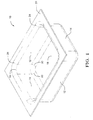
- Pan 10 is generally rectangular with an inside length of 386 mm and an inside width of 309 mm.
- the radius 16 between side walls 12 and end walls 14 is 76.6 mm.
- the depth of the pan is 127 mm.
- the radius 20 between the bottom 18 of pan 10 and the side 12 and end 14 walls is 25.4 mm.
- the radius 24 between the top flange 22 and the side and end walls is 8.1 mm.
- the pan configuration was chosen for evaluation of the subject SPF stretch-forming process because it requires drastic elongation and deformation of portions of a sheet blank and often results in excessive thinning or tearing of the material, particularly in the region of the bottom 18 or bottom radius 20.
- Pan 10 was formed using 1.2 mm thick sheet of a commercially available, superplastic formable Aluminum Alloy 5083.
- the 5083 alloy had a nominal composition, by weight, of 4 to 4.9% magnesium, 0.4 to 1% manganese, 0.05 to 0.25% chromium, about 0.1% copper and the balance aluminum.
- the cold-rolled sheet had been processed for SPF and had a fine, stable grain structure ( ⁇ 10 ⁇ m) suitable for SPF.
- the sheets were lubricated with boron nitride before superplastic forming. Forming was done at about 500°C at a strain rate in the range of 10 -4 to 10 -3 second -1 .
- the forming cycle time was six minutes.
- the stretch forming tooling 30 comprises lower platen 32 and upper die platen 34 carrying the female forming die 36.
- Die 36 shown in section, has forming surfaces 38, 40, 42 and 44 that define a cavity 46.
- Die surface 38 corresponds to pan bottom 18.
- Die surfaces 40 correspond to pan side walls 12.
- Die surfaces 42 correspond to pan bottom radii 20 and surfaces 44 correspond to flange radii 24.
- Die surfaces 44 terminate in flat die surfaces 48 that serve to form the flanges 22 of pan 10 and to engage a sheet metal blank as will be more fully described. Obviously, blank sheet metal must be forced into cavity 46 against the respective forming surfaces to deform it into the shape of the pan.
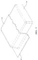
- Steel preform block 50 is positioned on lower platen 32 so that it underlies and is opposite cavity 46.
- Block 50 is a rounded rectangular block with a flat top having dimensions slightly smaller than the dimensions of cavity 46.
- the specific dimensions of block 50 were 205 mm long x 292 mm wide x 50.8 mm high.
- Block 50 is shown as being a single piece. Obviously, any preform may be formed of a plurality of pieces.
- a sheet 60 of SPF Aluminum alloy 5083 is placed on the top of preform 50.
- the sheet 60 was rectangular in shape with dimensions of 533 mm by 635 mm.
- Sheet 60 is sized so that its edges 62 extend outside the reach of forming die surfaces 48.
- the sheet and die members 32 and 36 are electrically heated by resistance elements, not shown, to the desired SPF temperature - in this case about 500°C for the 5083 alloy.
- the upper forming die 36 is then slowly lowered toward die platen 32 into engagement with the periphery of sheet 60 ( Figure 2B). As die 36 is lowered. it pulls the heated sheet 60 down around insert 50. More of the material of the initially flat sheet 60 is thus drawn into the cavity region 46 of the forming die 36.
- die 36 is fully lowered against the edges 62 of sheet 60,0 it presses the edges into sealing engagement with the complementary surface 64 of platen 32. Obviously, much more of the sheet has been drawn into die cavity 48 than would have been enclosed within the die if the sheet had simply been stretched flat between the die members (see Figure 3).
- high pressure gas such as nitrogen or argon
- gas may be admitted against the back side 66 of heated sheet 60 through a suitable gas passage (not shown) in platen 32 or other suitable location.
- gas may be vented from die cavity 46 through vent passages (not shown) in die 36 or other suitable location.
- Die 36 engages front surface 68 at edges 62 of sheet 60.
- Die platen 32 engages the back side 66 at the edges 62 of sheet 60.
- the die members grip the sheet 60 in gas-tight sealing lockbead (not shown) engagement so that suitable gas pressure is maintained on the back side of the soft sheet to stretch it into full compliance with the forming surfaces of die 32.
- Sheet 60 is gripped at edges 62 so that the blow-forming step occurs substantially entirely by stretching (see Figure 2C).
- This high pressure blow-forming operation was conducted by gradually increasing the argon pressure to 62 kPa over a period of four minutes. As stated, the complete forming step of the pan after die closure took six minutes. The pressure was then relieved, the dies opened and a completed pan 10 was removed. The pan formed completely without splits or significant cavitation.
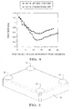
- FIG. 4 is a graph of pan wall thickness in 12.7 mm increments measured from the lockbead ridge on the flange of the pans.
- the thickness values for the pan made with the insert as described above are shown as filled circles (•).
- the initial thickness of the commercial SPF 5083 sheet was 1.2 mm.
- the pan made without a preform was made with a second material, a premium SPF grade 1.2 mm 5083 sheet because the pan could not be made by the originally-selected commercial SPF sheet without tearing.
- the thickness data for the conventional SPF pan is entered as open circles ( ⁇ ). It is clearly seen that the pan formed using the preform of this invention had a much thicker bottom and more uniform thickness than the pan made without a preform, i.e., solely by SPF.
- the minimum thickness in the pan made using a preform was 0.55 mm compared to 0.28 mm in the non-preform pan, while the bottom thickness was 0.66 mm compared to 0.40 mm in the non-preform pan.
- the practice of the invention has been described using AA 5083 that had been specially processed for SPF.
- the invention may also be practiced using other aluminum or titanium alloys, e.g.. or with conventionally-processed aluminum alloys such as 5182 or 5454. Any material or process capable of producing substantial thickness reductions. e.g.. 50% or more, can benefit from this invention.
- the preform used to gather material and produce draw-in was rectangular with rounded corners roughly the size of the SPF die.
- a variety of insert geometries can be used to produce draw-in including domes and cylinders.
- the amount of material draw-in is controlled by the height, shape and position of the male preform
- the preform may be tailored to produce a desired strain distribution. For example, a rectangular preform 70 with four raised corners 72 (see Figure 5) serves to increase the thickness of corner sections in pan shapes as described above.
- the shape of the preform is intentionally kept simple to perform the required draw-in of the aluminum while minimizing costly three-dimensional sculpturing that is required in a multi-part, matched stamping die.
- a double action press could be used to provide the sealing pressure for forming as well as the motion of a punch acting on the backside of the sheet blank to create draw-in.
- a key component in this arrangement would be a two-part sealing/binder ring that allowed draw-in and upon further actuation provided suitable pressure for gas sealing.
- Another alternative to preforms placed on a stationary die is the use of nitrogen pressure, either alone or in combination with a double action press, to produce draw-in during SPF. The nitrogen pressure could be used to activate a punch, produce the clamping force for the draw-in operation, or to activate a sealing bead.
Landscapes
- Physics & Mathematics (AREA)
- Fluid Mechanics (AREA)
- Engineering & Computer Science (AREA)
- Mechanical Engineering (AREA)
- Shaping Metal By Deep-Drawing, Or The Like (AREA)
- Blow-Moulding Or Thermoforming Of Plastics Or The Like (AREA)
Claims (6)
- Verfahren zum Streckformen einer flachen verformbaren Metalltafel (60), um eine Metallausdünnung und Risse in dem geformten Produkt zu vermindern, wobei das Verfahren umfasst, dass:die Tafel zwischen ersten (36) und zweiten (32) Matrizenelementen angeordnet wird, die zwischen einer Stellung mit offener Matrize, um die Tafel (60) einzusetzen und ein geformtes Produkt (10) zu entfernen, und einer Stellung mit geschlossener Matrize bewegbar sind, in der die Matrizen (32, 36) mit der Peripherie (62) der Tafel (60) in Eingriff treten, wobei das erste Matrizenelement (36) eine Formfläche (38, 40, 42, 44) aufweist und einen Hohlraum (46) zwischen der Formfläche (38, 40, 42, 44) und einer ersten Fläche der Tafel definiert, wobei die zweite Matrize (32) eine Metalltafelformfläche (50), die dem Hohlraum (46) gegenüberliegt, aufweist, wobei sich die Matrizen (32, 36) in ihrer offenen Stellung befinden und die Tafel (60) zwischen der Metalltafelformfläche (50) und dem Hohlraum (46) positioniert wird;die Tafel (60) auf eine Streckformtemperatur erwärmt wird;die Matrizen in ihre geschlossene Stellung bewegt werden, so dass der erste (36) Matrize mit der Peripherie (62) der Tafel (60) in Eingriff tritt und die Formfläche (50) der zweiten Matrize mit der Tafel (60) in Eingriff tritt, um Tafelmaterial in den Hohlraum (46) zu ziehen, so dass die Tafel (60) nicht mehr flach ist und mehr Tafelmaterial in ihrer in Eingriff stehenden Peripherie (62) angeordnet ist, als, wenn die Tafel flach geblieben wäre; unddie Tafel in Konformität mit der Formfläche der ersten Matrize streckgeformt wird.
- Verfahren nach Anspruch 1, wobei das Metall eine Aluminiumlegierung ist.
- Verfahren nach Anspruch 1 oder 2, wobei das Tafelmetall superplastisch formbar ist und auf eine zur superplastischen Formung geeignete Temperatur vor oder während des Schließens der Matrizen erwärmt wird.
- Verfahren nach einem der Ansprüche 1 oder 2, wobei das Tafelmetall eine superplastisch verformbare Aluminiumlegierung 5083 ist, die auf eine zur superplastischen Formung geeignete Temperatur oberhalb 400°C vor oder während des Schließens der Matrizen erwärmt wird.
- Verfahren nach einem der Ansprüche 1 oder 2, wobei die Formfläche mit einer Gestaltung ausgebildet ist, die geometrisch ähnlich zu der Hohlraumfläche ist.
- Verfahren nach einem der Ansprüche 1 bis 5, wobei die Matrizen (32, 36) abdichtend mit der Peripherie (62) der Tafel (60) zur Streckformung des von den Matrizen umschlossenen Bereiches der Tafel unter Verwendung von unterschiedlichem Gasdruck in Eingriff treten; und ein Gasdruck auf die zweite Seite der Tafel aufgebracht wird, um die Tafel in Konformität mit der Formfläche der ersten Matrize zu strecken.
Applications Claiming Priority (3)
| Application Number | Priority Date | Filing Date | Title |
|---|---|---|---|
| US09/089,634 US5974847A (en) | 1998-06-02 | 1998-06-02 | Superplastic forming process |
| US89634 | 1998-06-02 | ||
| PCT/US1999/009585 WO1999062653A1 (en) | 1998-06-02 | 1999-04-30 | Superplastic forming process |
Publications (2)
| Publication Number | Publication Date |
|---|---|
| EP1007240A1 EP1007240A1 (de) | 2000-06-14 |
| EP1007240B1 true EP1007240B1 (de) | 2003-10-01 |
Family
ID=22218733
Family Applications (1)
| Application Number | Title | Priority Date | Filing Date |
|---|---|---|---|
| EP99922769A Expired - Lifetime EP1007240B1 (de) | 1998-06-02 | 1999-04-30 | Superplastisches formierungsverfahren |
Country Status (6)
| Country | Link |
|---|---|
| US (1) | US5974847A (de) |
| EP (1) | EP1007240B1 (de) |
| AU (1) | AU741012B2 (de) |
| CA (1) | CA2306555C (de) |
| DE (1) | DE69911724T2 (de) |
| WO (1) | WO1999062653A1 (de) |
Families Citing this family (59)
| Publication number | Priority date | Publication date | Assignee | Title |
|---|---|---|---|---|
| TW496823B (en) * | 1998-12-23 | 2002-08-01 | Dung-Han Juang | Process for manufacturing an electromagnetic interference shielding superplastic alloy foil cladded plastic outer shell product |
| TW420969B (en) * | 2000-01-28 | 2001-02-01 | Metal Ind Redearch & Dev Ct | Method of producing thin metal case with joint element |
| US6253588B1 (en) * | 2000-04-07 | 2001-07-03 | General Motors Corporation | Quick plastic forming of aluminum alloy sheet metal |
| DE60136355D1 (de) * | 2000-05-11 | 2008-12-11 | Autoform Engineering Gmbh | Verfahren zum entwickeln von werkzeugen |
| US6516645B2 (en) | 2000-12-27 | 2003-02-11 | General Motors Corporation | Hot die cleaning for superplastic and quick plastic forming |
| US6485585B2 (en) | 2001-02-26 | 2002-11-26 | General Motors Corporation | Method for making sheet metal components with textured surfaces |
| US6305202B1 (en) | 2001-03-30 | 2001-10-23 | General Motors Corporation | Rotatable stuffing device for superplastic forming and method |
| US6615631B2 (en) | 2001-04-19 | 2003-09-09 | General Motors Corporation | Panel extraction assist for superplastic and quick plastic forming equipment |
| US6845839B2 (en) * | 2001-08-23 | 2005-01-25 | General Motors Corporation | Vehicle body platform |
| US6675621B2 (en) | 2001-09-10 | 2004-01-13 | General Motors Corporation | Plural sheet superplastic forming equipment and process |
| US6793275B1 (en) | 2001-11-27 | 2004-09-21 | General Motors Corporation | Load-bearing body panel assembly for a motor vehicle |
| US7441615B2 (en) * | 2001-12-07 | 2008-10-28 | General Motors Corporation | Modular chassis with simplified body-attachment interface |
| US6581428B1 (en) * | 2002-01-24 | 2003-06-24 | Ford Motor Company | Method and apparatus for superplastic forming |
| US6694790B2 (en) | 2002-04-17 | 2004-02-24 | General Motors Corporation | Mid plate process and equipment for the superplastic forming of parts from plural sheets |
| US6837087B2 (en) * | 2002-09-13 | 2005-01-04 | General Motors Corporation | Guide pin slot arrangement for super plastic forming blanks providing improved blank guidance and formed part release |
| US6776020B2 (en) | 2002-10-11 | 2004-08-17 | General Motors Corporation | Method for stretching forming and transporting and aluminum metal sheet |
| US6810709B2 (en) | 2002-10-11 | 2004-11-02 | General Motors Corporation | Heated metal forming tool |
| US6799450B2 (en) | 2002-10-11 | 2004-10-05 | General Motors Corporation | Method of stretch forming an aluminum metal sheet and handling equipment for doing the same |
| US6886383B2 (en) * | 2002-11-04 | 2005-05-03 | General Motors Corporation | Method for stretch forming sheet metal by pressing and the application of gas pressure |
| US6825442B2 (en) | 2003-01-06 | 2004-11-30 | General Motors Corporation | Tailor welded blank for fluid forming operation |
| US7130708B2 (en) * | 2003-04-01 | 2006-10-31 | General Motors Corporation | Draw-in map for stamping die tryout |
| US6948226B2 (en) * | 2003-04-02 | 2005-09-27 | General Motors Corporation | Chassis frame packaging cavity loading method |
| US20040194280A1 (en) * | 2003-04-07 | 2004-10-07 | Borroni-Bird Christopher E. | Rolling chassis and assembled bodies |
| US20040216386A1 (en) * | 2003-04-29 | 2004-11-04 | Chernoff Adrian B. | Vehicle door having unitary inner panel and outer panel |
| US7040688B2 (en) * | 2003-04-29 | 2006-05-09 | General Motors Corporation | Vehicle door |
| US6805397B1 (en) | 2003-04-30 | 2004-10-19 | General Motors Corporation | Vehicle door |
| US6921601B2 (en) * | 2003-05-16 | 2005-07-26 | General Motors Corporation | Fuel cell stack humidification method incorporating an accumulation device |
| US6886885B2 (en) * | 2003-07-01 | 2005-05-03 | General Motors Corporation | Rear and side panel assembly for a vehicle and a method of assembling a vehicle |
| US7032958B2 (en) * | 2003-07-01 | 2006-04-25 | General Motors Corporation | Body and frame assembly for a vehicle and method of assembling a vehicle |
| US7077439B2 (en) * | 2003-08-25 | 2006-07-18 | General Motors Corporation | Vehicle bumper and method of making same |
| US7112249B2 (en) * | 2003-09-30 | 2006-09-26 | General Motors Corporation | Hot blow forming control method |
| US7516529B2 (en) * | 2003-12-17 | 2009-04-14 | General Motors Corporation | Method for producing in situ metallic foam components |
| US7100259B2 (en) * | 2003-12-17 | 2006-09-05 | General Motors Corporation | Method of metallic sandwiched foam composite forming |
| US7225542B2 (en) * | 2004-01-23 | 2007-06-05 | General Motors Corporation | Vehicle body compartment lid method of manufacturing |
| US7111900B2 (en) * | 2004-01-23 | 2006-09-26 | General Motors Corporation | Vehicle floor having a unitary inner panel and outer panel |
| US20050179242A1 (en) * | 2004-02-03 | 2005-08-18 | Chernoff Adrian B. | Vehicle front seat configuration |
| US7310878B2 (en) * | 2004-02-27 | 2007-12-25 | Gm Global Technology Operations, Inc. | Automotive lower body component method of manufacture |
| US20050189790A1 (en) * | 2004-02-27 | 2005-09-01 | Chernoff Adrian B. | Automotive side frame and upper structure and method of manufacture |
| US7159931B2 (en) * | 2004-02-27 | 2007-01-09 | Gm Global Technology Operations, Inc. | Automotive roof rack and accessories manufactured with QPF/SPF technology |
| US7766414B2 (en) * | 2004-02-27 | 2010-08-03 | Gm Global Technology Operations, Inc. | Mixed metal closure assembly and method |
| US20060068112A1 (en) * | 2004-09-29 | 2006-03-30 | Chapman Lloyd R | Recycling process for boron nitride |
| US7284402B2 (en) * | 2004-11-30 | 2007-10-23 | Ford Global Technologies, L.L.C. | System and process for superplastic forming |
| US7266982B1 (en) | 2005-06-10 | 2007-09-11 | Guza David E | Hydroforming device and method |
| US7434432B1 (en) * | 2005-08-18 | 2008-10-14 | Hi-Tech Welding And Forming, Inc. | Die apparatus and method for high temperature forming of metal products |
| US7827840B2 (en) * | 2006-11-30 | 2010-11-09 | Ford Global Technologies, Llc | Multistage superplastic forming apparatus and method |
| US7654125B2 (en) * | 2007-02-06 | 2010-02-02 | Gm Global Technology Operations, Inc. | Metal forming apparatus |
| US8381562B2 (en) * | 2007-02-06 | 2013-02-26 | GM Global Technology Operations LLC | Metal forming apparatus characterized by rapid cooling and method of use thereof |
| US20080235935A1 (en) | 2007-03-06 | 2008-10-02 | Dong Woo Kang | Laundry treating apparatus |
| US7472572B2 (en) | 2007-04-26 | 2009-01-06 | Ford Global Technologies, Llc | Method and apparatus for gas management in hot blow-forming dies |
| US20080265591A1 (en) * | 2007-04-30 | 2008-10-30 | International Truck Intellectual Property Company, Llc | Superplastic aluminum vehicle bumper |
| EP2090668A1 (de) * | 2008-01-30 | 2009-08-19 | Corus Staal BV | Verfahren zur Herstellung eines hochfesten Stahls und dadurch gewonnener hochfester Stahl |
| US9522419B2 (en) * | 2008-05-05 | 2016-12-20 | Ford Global Technologies, Llc | Method and apparatus for making a part by first forming an intermediate part that has donor pockets in predicted low strain areas adjacent to predicted high strain areas |
| US20090272171A1 (en) * | 2008-05-05 | 2009-11-05 | Ford Global Technologies, Llc | Method of designing and forming a sheet metal part |
| SE532913C2 (sv) * | 2008-09-30 | 2010-05-04 | Alfa Laval Corp Ab | Förfarande och pressverktyg för tillverkning av en separeringsskiva |
| US8499607B2 (en) * | 2009-08-28 | 2013-08-06 | GM Global Technology Operations LLC | Forming of complex shapes in aluminum and magnesium alloy workpieces |
| US20110061406A1 (en) * | 2009-09-15 | 2011-03-17 | Gm Global Tehnology Operations, Inc. | Method of cooling stretch-formed-part |
| CA2759140A1 (en) | 2010-11-24 | 2012-05-24 | Magna Closures Inc. | Solar panel system |
| JP5951632B2 (ja) | 2010-12-17 | 2016-07-13 | マグナ インターナショナル インコーポレイテッド | 超塑性成形用ブランク |
| US10166590B2 (en) | 2015-09-25 | 2019-01-01 | Tesla, Inc. | High speed blow forming processes |
Family Cites Families (11)
| Publication number | Priority date | Publication date | Assignee | Title |
|---|---|---|---|---|
| US3373585A (en) * | 1964-09-21 | 1968-03-19 | Reynolds Tobacco Co R | Sheet metal shaping apparatus and method |
| US4145903A (en) * | 1978-04-03 | 1979-03-27 | Textron Inc. | Sheet forming method and apparatus |
| DE2839469A1 (de) * | 1978-09-11 | 1980-03-20 | Rockwell International Corp | Verfahren zur herstellung eines metallgebildes |
| US4269053A (en) * | 1979-07-25 | 1981-05-26 | Rockwell International Corporation | Method of superplastic forming using release coatings with different coefficients of friction |
| US4354369A (en) * | 1980-05-16 | 1982-10-19 | Rockwell International Corporation | Method for superplastic forming |
| US4352280A (en) * | 1980-05-16 | 1982-10-05 | Rockwell International Corporation | Compression forming of sheet material |
| US4381657A (en) * | 1980-05-19 | 1983-05-03 | Rockwell International Corporation | Method of removing formed parts from a die |
| GB8502772D0 (en) * | 1985-02-04 | 1985-03-06 | Tkr Int | Pressing contoured shapes |
| US4741197A (en) * | 1986-04-25 | 1988-05-03 | Aluminum Company Of America | Ejection of superplastically formed part with minimum distortion |
| JPH0215835A (ja) * | 1988-06-30 | 1990-01-19 | Suzuki Motor Co Ltd | 複合液圧プレス加工方法 |
| US4984348A (en) * | 1989-01-17 | 1991-01-15 | Rohr Industries, Inc. | Superplastic drape forming |
-
1998
- 1998-06-02 US US09/089,634 patent/US5974847A/en not_active Expired - Lifetime
-
1999
- 1999-04-30 CA CA002306555A patent/CA2306555C/en not_active Expired - Fee Related
- 1999-04-30 EP EP99922769A patent/EP1007240B1/de not_active Expired - Lifetime
- 1999-04-30 WO PCT/US1999/009585 patent/WO1999062653A1/en not_active Ceased
- 1999-04-30 DE DE69911724T patent/DE69911724T2/de not_active Expired - Lifetime
- 1999-04-30 AU AU39691/99A patent/AU741012B2/en not_active Ceased
Also Published As
| Publication number | Publication date |
|---|---|
| EP1007240A1 (de) | 2000-06-14 |
| CA2306555A1 (en) | 1999-12-09 |
| AU741012B2 (en) | 2001-11-22 |
| CA2306555C (en) | 2004-08-17 |
| US5974847A (en) | 1999-11-02 |
| DE69911724D1 (de) | 2003-11-06 |
| AU3969199A (en) | 1999-12-20 |
| DE69911724T2 (de) | 2004-07-29 |
| WO1999062653A1 (en) | 1999-12-09 |
Similar Documents
| Publication | Publication Date | Title |
|---|---|---|
| EP1007240B1 (de) | Superplastisches formierungsverfahren | |
| US6253588B1 (en) | Quick plastic forming of aluminum alloy sheet metal | |
| US4811890A (en) | Method of eliminating core distortion in diffusion bonded and uperplastically formed structures | |
| US6910358B2 (en) | Two temperature two stage forming | |
| EP1052036B1 (de) | Verbesserte Dichtungswulst zum superplastische Verformung eines Aluminiumbleches | |
| US7225542B2 (en) | Vehicle body compartment lid method of manufacturing | |
| EP1410856B1 (de) | Verfahren zum Herstellen eines Blechartikels durch superplastische oder schnelle plastische Verformung | |
| EP1415735B1 (de) | Verfahren zum Herstellen eines Blechartikels durch superplastische oder schnelle plastische Verformung | |
| US4559797A (en) | Method for forming structural parts | |
| US7472572B2 (en) | Method and apparatus for gas management in hot blow-forming dies | |
| EP1331049B1 (de) | Verfahren und Vorrichtung zum superplastischen Verformen | |
| JP2001162330A (ja) | 面積の大きな金属薄板部材を製作する方法 | |
| US7047779B2 (en) | Curvilinear punch motion for double-action hot stretch-forming | |
| US4113522A (en) | Method of making a metallic structure by combined superplastic forming and forging | |
| US20040216386A1 (en) | Vehicle door having unitary inner panel and outer panel | |
| US7363790B2 (en) | Method for vaccum assisted preforming of superplastically or quick plastically formed article | |
| US5215600A (en) | Thermomechanical treatment of Ti 6-2-2-2-2 | |
| GB2029304A (en) | Method of making a metallic structure | |
| CA1083859A (en) | Method of making a metallic structure by combined superplastic forming and forging | |
| Padmanabhan et al. | Applications of Superplasticity | |
| GB2126935A (en) | Method of removing formed parts from a die |
Legal Events
| Date | Code | Title | Description |
|---|---|---|---|
| PUAI | Public reference made under article 153(3) epc to a published international application that has entered the european phase |
Free format text: ORIGINAL CODE: 0009012 |
|
| 17P | Request for examination filed |
Effective date: 20000322 |
|
| AK | Designated contracting states |
Kind code of ref document: A1 Designated state(s): DE FR GB IT SE |
|
| RIN1 | Information on inventor provided before grant (corrected) |
Inventor name: SCHROTH, JAMES, G. Inventor name: RYNTZ, EDWARD, F. Inventor name: KRAJEWSKI, PAUL, E. Inventor name: SAUNDERS, FREDERICK |
|
| 17Q | First examination report despatched |
Effective date: 20020709 |
|
| GRAH | Despatch of communication of intention to grant a patent |
Free format text: ORIGINAL CODE: EPIDOS IGRA |
|
| GRAS | Grant fee paid |
Free format text: ORIGINAL CODE: EPIDOSNIGR3 |
|
| GRAA | (expected) grant |
Free format text: ORIGINAL CODE: 0009210 |
|
| AK | Designated contracting states |
Kind code of ref document: B1 Designated state(s): DE FR GB IT SE |
|
| REG | Reference to a national code |
Ref country code: GB Ref legal event code: FG4D |
|
| REF | Corresponds to: |
Ref document number: 69911724 Country of ref document: DE Date of ref document: 20031106 Kind code of ref document: P |
|
| REG | Reference to a national code |
Ref country code: SE Ref legal event code: TRGR |
|
| ET | Fr: translation filed | ||
| PLBE | No opposition filed within time limit |
Free format text: ORIGINAL CODE: 0009261 |
|
| STAA | Information on the status of an ep patent application or granted ep patent |
Free format text: STATUS: NO OPPOSITION FILED WITHIN TIME LIMIT |
|
| 26N | No opposition filed |
Effective date: 20040702 |
|
| REG | Reference to a national code |
Ref country code: GB Ref legal event code: 732E Free format text: REGISTERED BETWEEN 20090226 AND 20090304 |
|
| REG | Reference to a national code |
Ref country code: GB Ref legal event code: 732E Free format text: REGISTERED BETWEEN 20090305 AND 20090311 |
|
| REG | Reference to a national code |
Ref country code: GB Ref legal event code: 732E Free format text: REGISTERED BETWEEN 20091029 AND 20091104 |
|
| REG | Reference to a national code |
Ref country code: GB Ref legal event code: 732E Free format text: REGISTERED BETWEEN 20091105 AND 20091111 |
|
| REG | Reference to a national code |
Ref country code: FR Ref legal event code: TP Ref country code: FR Ref legal event code: CD |
|
| REG | Reference to a national code |
Ref country code: DE Ref legal event code: R081 Ref document number: 69911724 Country of ref document: DE Owner name: GENERAL MOTORS LLC ( N. D. GES. D. STAATES DEL, US Free format text: FORMER OWNER: GENERAL MOTORS COMPANY, DETROIT, MICH., US Effective date: 20110428 Ref country code: DE Ref legal event code: R081 Ref document number: 69911724 Country of ref document: DE Owner name: GENERAL MOTORS LLC ( N. D. GES. D. STAATES DEL, US Free format text: FORMER OWNER: GENERAL MOTORS COMPANY, DETROIT, US Effective date: 20110428 |
|
| PGFP | Annual fee paid to national office [announced via postgrant information from national office to epo] |
Ref country code: FR Payment date: 20110426 Year of fee payment: 13 Ref country code: SE Payment date: 20110412 Year of fee payment: 13 |
|
| PGFP | Annual fee paid to national office [announced via postgrant information from national office to epo] |
Ref country code: IT Payment date: 20110422 Year of fee payment: 13 |
|
| REG | Reference to a national code |
Ref country code: SE Ref legal event code: EUG |
|
| REG | Reference to a national code |
Ref country code: FR Ref legal event code: ST Effective date: 20121228 |
|
| PG25 | Lapsed in a contracting state [announced via postgrant information from national office to epo] |
Ref country code: IT Free format text: LAPSE BECAUSE OF NON-PAYMENT OF DUE FEES Effective date: 20120430 Ref country code: FR Free format text: LAPSE BECAUSE OF NON-PAYMENT OF DUE FEES Effective date: 20120430 Ref country code: SE Free format text: LAPSE BECAUSE OF NON-PAYMENT OF DUE FEES Effective date: 20120501 |
|
| PGFP | Annual fee paid to national office [announced via postgrant information from national office to epo] |
Ref country code: DE Payment date: 20170426 Year of fee payment: 19 Ref country code: GB Payment date: 20170426 Year of fee payment: 19 |
|
| REG | Reference to a national code |
Ref country code: DE Ref legal event code: R119 Ref document number: 69911724 Country of ref document: DE |
|
| GBPC | Gb: european patent ceased through non-payment of renewal fee |
Effective date: 20180430 |
|
| PG25 | Lapsed in a contracting state [announced via postgrant information from national office to epo] |
Ref country code: DE Free format text: LAPSE BECAUSE OF NON-PAYMENT OF DUE FEES Effective date: 20181101 |
|
| PG25 | Lapsed in a contracting state [announced via postgrant information from national office to epo] |
Ref country code: GB Free format text: LAPSE BECAUSE OF NON-PAYMENT OF DUE FEES Effective date: 20180430 |