EP1006484A2 - Verfahren zur Schätzung von volumetrischen Abstandkarten aus 2D Tiefebildern - Google Patents
Verfahren zur Schätzung von volumetrischen Abstandkarten aus 2D Tiefebildern Download PDFInfo
- Publication number
- EP1006484A2 EP1006484A2 EP99120302A EP99120302A EP1006484A2 EP 1006484 A2 EP1006484 A2 EP 1006484A2 EP 99120302 A EP99120302 A EP 99120302A EP 99120302 A EP99120302 A EP 99120302A EP 1006484 A2 EP1006484 A2 EP 1006484A2
- Authority
- EP
- European Patent Office
- Prior art keywords
- distance
- projected
- volume
- map
- distance map
- Prior art date
- Legal status (The legal status is an assumption and is not a legal conclusion. Google has not performed a legal analysis and makes no representation as to the accuracy of the status listed.)
- Withdrawn
Links
Images


Classifications
-
- G—PHYSICS
- G06—COMPUTING OR CALCULATING; COUNTING
- G06T—IMAGE DATA PROCESSING OR GENERATION, IN GENERAL
- G06T15/00—3D [Three Dimensional] image rendering
- G06T15/10—Geometric effects
- G06T15/40—Hidden part removal
-
- G—PHYSICS
- G06—COMPUTING OR CALCULATING; COUNTING
- G06T—IMAGE DATA PROCESSING OR GENERATION, IN GENERAL
- G06T15/00—3D [Three Dimensional] image rendering
- G06T15/06—Ray-tracing
-
- H—ELECTRICITY
- H04—ELECTRIC COMMUNICATION TECHNIQUE
- H04N—PICTORIAL COMMUNICATION, e.g. TELEVISION
- H04N13/00—Stereoscopic video systems; Multi-view video systems; Details thereof
- H04N13/10—Processing, recording or transmission of stereoscopic or multi-view image signals
- H04N13/106—Processing image signals
- H04N13/128—Adjusting depth or disparity
Definitions
- the invention relates generally to computer graphics, and more particularly to estimating 3D distance maps from 2D depth images.
- Distance maps are typically 2D or 3D discrete arrays of sampled values.
- the sampled values represent distances to the closest points on the surface of an object that is modeled in a computer.
- the zero-value iso-surface of a signed distance map represents the surface of the object.
- the gradient vector of the distance map points in the direction of the closest surface point, and hence, for points near object surfaces, the gradient of the distance map is a good approximation of the surface normal of the object.
- Object scanning is the process of acquiring a computer model of a real-world object from image or range data. Scanning is done with many techniques. Most methods generate a "cloud,” or grid, of 3D points that lie on the object's surface. A model of the object is constructed by fitting surfaces to these points. However, as was discussed in Gibson's "Using Distance Maps for Accurate Surface Representation in Sampled Volumes," distance maps provide a much more robust representation of object surfaces than sampled object points. Hence, if the range images were used to generate 3D distance maps, rather than clouds of surface points, then better scanned models can be obtained.
- the distance map is determined by finding the closest polygon, edge, or vertex in the model, and calculating the distance to that feature.
- One straightforward method for doing this is to consider each grid point in the distance map individually, find the closest polygon in the model by searching the list of polygons, and then calculating the distance from the grid point to that closest polygon.
- a second straightforward method is to consider each polygon in the object model one at a time, calculate the distance from the polygon to each grid point within a limited distance from the polygon, and replace each grid value in the distance map if the new distance has a smaller magnitude than the existing value.
- both of these methods for calculating distance maps from a polygonal model are adequate, when the distance map is calculated for a static object in a pre-processing step. However, both of these methods are unsuitable for time constrained interactive applications in which the shape or topology of the polygon model is changing.
- the present invention approximates 3D distance maps from range images of real-world objects or from triangulated object models using single or multiple projected 2D depth images.
- the invention can be used in systems where 2D depth images of real-world objects are obtained with range sensing devices, or in systems where the 2D depth images of virtual object models are obtained by calculating the projected distance from each point in the depth image to the object model.
- These systems can include means for performing the projection particularly fast using polygon rendering hardware and a graphics z-buffer.
- distance maps are a discrete representation of the distance from grid points in the volume to the closest point on the object surface.
- an interpolation function such as tri-linear interpolation
- distances at grid points can be used to estimate the closest distance from any point within the volume to the surface.
- the gradient of the distance map can be used to estimate the surface normal.
- Distances to object surfaces can be used in a number of applications.
- the distance maps can be used to determine a path that stays a minimum distance away from objects or an obstacle-free path with minimum length for a mobile robot.
- distance maps can be used in volume rendering to detect surfaces and surface normals that are required for determining surface reflections in shaded volume rendering.
- distance maps can be used in haptics, where an electromechanical device allows the user to "feel" the surface of a virtual object by providing force feedback to resist the user's tool when the tool penetrates the surface of the virtual object.
- Haptic feedback requires both the depth of penetration of the tool into the virtual object and the normal of the closest surface point to generate the resisting force vector.
- the present invention generates 3D distance maps from 2D projected depth images. Accordingly, a projected distance volume is generated from the depth image. Each sample in the projected distance volume is the distance to a surface point of the object in the projection direction. The distances in the projected volume are adjusted according the local gradient of the projected volume. More specifically, the distance is divided by the magnitude of the corresponding local gradient. The thus adjusted distances of the projected volume correctly represent the true distance map for planar surfaces, and closely approximate the true distance map near curved surfaces of the object.
- the present invention can be used in a system that uses graphics hardware and a graphics z-buffer to rapidly calculate the 2D projected depth images which are used to generate the projected distance volume for the above method.
- the invention can be used with a system that uses multiple range images acquired by a range sensor of a real-world object, and the above method for approximating distance maps from projected depth images for 3D scanning.
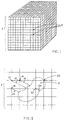
- distance maps are 2D or 3D grids 2 of sampled points 4. Each sample point represents the distance to the closest surface point of a represented object.
- distances from an object 6 to points in the grid 8 are represented as follows.
- Distances 12, 16, and 20 are negative distances from the edge of the 2D object to the exterior points 10, 14, and 18 respectively.
- Distance 24 is a positive distance to the interior point 22, and a distance of zero is recorded for the point 26.
- Point 26 is located exactly on the edge of the 2D object.
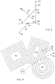
- the distances from a 3D triangle 30 with vertices v1, v2, and v3 can be calculated as follows. For points that are closest to the face of the triangle, such as point 48, the distance 50 to the closest point on the triangle 52 can be calculated as the magnitude of the dot product of the vector from the point to one of the vertices of the triangle and the triangle normal.
- the distance 40 to the closest point on the edge 42 can be calculated as the magnitude of the cross product of the normalized vector along the edge from v1 to v3 and the vector from the point 38 to the vertex v3.
- the distance 46 to the vertex 34 can be calculated as the magnitude of the vector from the point to the vertex.
- distance maps can be used for path planning and obstacle avoidance in robotics.
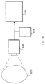
- This figure illustrates a system that determines a path for a robot with footprint 60 through an environment with obstacles 62, 64, and 66.
- One approach is to generate a 2D distance map of the robot's environment. Contours of increasing distances from the obstacles are indicated as 68, 70, and 72.
- the robot's operator is able to chose a path 74 which satisfies constraints on how closely the robot can come to the obstacles.
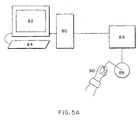
- distance maps can be used to calculate reaction forces for a haptic feedback device that is interacting with a virtual environment.
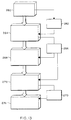
- a computer system 80 uses the distance map to detect collisions between the end effector of the haptic device and the object models, and calculates reaction forces due to impacts with the objects. The forces are converted by a haptic device controller 86 into control signals for the haptic device 88, and ultimately to reaction forces that are applied to the user 90.
- a computer monitor 82 provides visual feedback and other input devices, such as a keyboard 84, provide other means for interacting with the system.
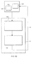
- FIG. 5B is a flow chart that illustrates the operation of such a haptic interaction system.
- the system includes a haptic device controller 100, and a computer system 102.
- the haptic device controller reads the position and orientation of the device end effector from a device encoders 104 and makes these available to the computer system.
- the haptic device controller also gets forces from the computer system and applies these to the device motors 106 to provide haptic feedback to the user.
- the computer system uses the distance map to determine whether the haptic end effector is contacting an object.
- the computer system calculates the distance and the normal of the closest object surface point for the given position of the haptic device in step 108.
- the system calculates the reaction force vector for the given object penetration 110 as the product of the spring constant of the object, the distance to the closest object surface point, and the normalized normal vector of the closest surface point. This calculated force is then sent to the haptic device controller as a signal via line 112.
- Figure 6 shows an example of pseudocode for performing shaded volume rendering from sampled volume data that contain color and transparency as well as distance map values.
- the distance map is first used to determine whether each sample point along rays cast into the volume are inside or outside of the object.
- the distance map is also used to calculate the gradient of object surfaces for shading the image.
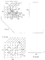
- Figure 7 shows a grid-based method for calculating the distance map from a triangulated model.
- each point in the grid 120 is considered once.
- the closest distances 124, 126, and 128 to the triangles 130, 132 and 134 are shown.
- the distances to all of the triangles in the triangle list 136 are calculated and the minimum distance is stored as the distance in the distance map as shown in a formulation 138.
- Figure 8A shows a triangle-based method for calculating the distance map.
- Each triangle 140 is considered once and a local region of the distance map for that triangle 142 is updated.
- grid points 144 and 146 are closest to the triangle face
- grid points 148 and 150 are closest to a triangle edge
- grid point 152 is closest to a triangle vertex.
- the distance is compared to the current distance stored in the distance map. If the magnitude of the new distance is smaller, then the distance in the distance map is replaced with the new distance as shown in the pseudocode of 154 shown in Figure 8B.
- the subject invention addresses this problem with a means for estimating the true distance map given a single or multiple projected depth images of the object model.
- a projected depth image 160 is a 2D image where the value of each point on the image grid is the distance to the object model 162.
- the distance is measured along parallel rays projected towards the object.
- the rays are cast to the object in a direction that is perpendicular to the depth image.
- the distance is measured at the first point where the ray intersects the object. For example, for point 164, the ray 166 intersects the object at 168 and the distance from 164 to 168 would be stored in the depth image.
- the distances from 170, 172, and 174 along the rays 176, 178, and 180 to the points 182 and 184 would be stored in the depth image.
- the ray 180 does not intersect the object.
- the distance stored at 174 is the distance to some pre-defined back plane. Using the convention that distances outside of the object are negative and distances inside of the object are positive, the distances at 164, 170, 172, and 174 would all be negative.
- a projected distance volume 190 for an object 192 is calculated from the projected depth image 194 as follows.
- the corresponding depth image point 196 is (i,j,0).
- the value k is assumed to have the same scale and units as the projected distance values. Note that adding a positive k to the negative value stored at 196 will result in a distance value of zero in the projected distance map at the object surface.
- a single depth image can only be used to partially reconstruct the volume distance map because occluded surfaces and surfaces that are substantially perpendicular to the depth image are not represented in the projected distance map. Because the resultant projected distance volume is view dependent, it is most useful when the approximate viewing direction, or position, of the haptic interaction device is known.
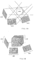
- a more complete projected distance map of the object can be obtained when multiple depth maps, 200, 202, and 204, are calculated for the object 206 as illustrated in Figure 11A.
- the distance at a point 208 in the combined projected distance map 210 is calculated as the minimum of the distance that is calculated for that point from the distance values at 212, 214, and 216 in the depth images 218, 220, and 222, respectively.
- the points 212, 214, and 216 do not necessarily lie at a grid point in their respective depth images. Hence, distances in the depth images may need to be interpolated in order to calculate the correct projected distances at the point 208 in the projected distance volume.
- a bilinear interpolation method can be used for this purpose.
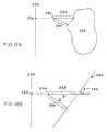
- Figure 12 shows that the projected distances that are calculated from depth images are not the same as the true minimum distances from a point to the object.
- the projected distance 230 from point 232 to the object 238 along the ray originating at the point 234 in the depth image 236 is significantly longer than the true distance 240.
- the gradient of the projected distance map when the gradient of the projected distance map is calculated using the central difference operator, the gradient has a magnitude of 2/sin(q) .
- the resultant adjusted distance map is equal to the true distance map for linear objects.
- the true distance map can be obtained from the projected distance map by dividing the projected distances by one half the magnitude of the gradient of the projected distance map. For objects that are piecewise planar or objects whose curvature is relatively small, then the adjusted projected distance map will approximate the true distance map quite well close to the object surface.
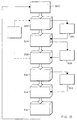
- Figure 13 shows the method steps for approximating the distance map for an object from single or multiple depth images.
- step 260 a single depth image or, alternatively, multiple depth images 262, are calculated or generated either from a computer model or from measurements from a real object. These depth images are then used in 264 to create the projected distance volume 266.
- step 268 the local gradient magnitude of the projected distance volume is determined at sample points throughout the volume. Each distance in the projected distance volume is then adjusted by dividing by one half of the magnitude of the local gradient of the projected distance volume. This adjusted distance map 270 is used as an approximation of the true distance map in the application.
- Figure 14 shows a system that uses graphics hardware and a z-buffer to calculate depth images for triangulated object models.
- An object model 280 on a computer CPU 282 is rendered onto the depth image plane with the graphics depth test activated using the graphics hardware 284.
- the depth image is then read from the graphics z-buffer and sent to the system which generates an approximate distance map from single or multiple depth images 282.
- This distance map is used in a number of applications such as haptics, rendering, physical modeling, and the like in step 288, which may result in modification of the object model, requiring that the distance map be recalculated.
- a monitor 290 and a haptic or other input device 292 can be used to give visual or haptic feedback and for user input.
- Figure 15 shows the operational steps for a system that uses the graphics hardware and the invention for fast approximation of distance maps from a triangulated object model.
- a triangulated object model 300 is rendered in step 302 with the graphics depth test activated.
- the z-buffer is read in step 304 to produce a projected depth image. This depth image is used to generate or improve a projected distance volume in step 308. If multiple depth images are used, steps 302 through 308 are repeated via line 310.
- the projected distance volume is then adjusted in step 312 by dividing distances by one half the magnitude of local gradient magnitudes of the projected distance volume.
- This adjusted distance map can be used to approximate the true distance map 314 in interactions with the object model for haptics, volume rendering, and physically-based simulations, step 316. When these interactions cause changes in the object shape or topology, the process is repeated to generate a new distance map.
- FIG. 16 a schematic diagram for a system that uses the subject invention for scanning the shape of a real world object is shown.
- the object 320 is scanned with a range scanner 322 to generate a 2D depth image 324 of the object.
- the depth image is sent to the computer 326. It will be appreciated that multiple depth images can be generated either by moving the camera or rotating the object.
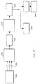
- FIG. 17 a flow chart of a system that uses the subject invention for scanning the shape of a real world object is shown.
- the scanning device 330 generates multiple depth images 332 from different views of the object. These depth images are interpolated and combined in step 334 to create a projected distance volume 336. The projected distance volume is then adjusted in step 338 to generate an approximate distance map 340.
- the accuracy of the approximate distance map will improve when more depth images are used to generate the projected distance map.
- the approximate distance map will then be used by the application.
- the distance map is used to provide a shaded volume rendered image of the object.
- a surface tiling method is used to convert the distance map to polygons and then the polygon model is rendered using graphics hardware.
Landscapes
- Engineering & Computer Science (AREA)
- Physics & Mathematics (AREA)
- Theoretical Computer Science (AREA)
- Computer Graphics (AREA)
- General Physics & Mathematics (AREA)
- Multimedia (AREA)
- Geometry (AREA)
- Signal Processing (AREA)
- Length Measuring Devices By Optical Means (AREA)
- Image Processing (AREA)
- Image Analysis (AREA)
- Image Generation (AREA)
- Analysing Materials By The Use Of Radiation (AREA)
Applications Claiming Priority (2)
| Application Number | Priority Date | Filing Date | Title |
|---|---|---|---|
| US206071 | 1998-12-04 | ||
| US09/206,071 US6262738B1 (en) | 1998-12-04 | 1998-12-04 | Method for estimating volumetric distance maps from 2D depth images |
Publications (2)
| Publication Number | Publication Date |
|---|---|
| EP1006484A2 true EP1006484A2 (de) | 2000-06-07 |
| EP1006484A3 EP1006484A3 (de) | 2003-07-09 |
Family
ID=22764857
Family Applications (1)
| Application Number | Title | Priority Date | Filing Date |
|---|---|---|---|
| EP99120302A Withdrawn EP1006484A3 (de) | 1998-12-04 | 1999-10-12 | Verfahren zur Schätzung von volumetrischen Abstandkarten aus 2D Tiefebildern |
Country Status (3)
| Country | Link |
|---|---|
| US (1) | US6262738B1 (de) |
| EP (1) | EP1006484A3 (de) |
| JP (1) | JP3178528B2 (de) |
Cited By (4)
| Publication number | Priority date | Publication date | Assignee | Title |
|---|---|---|---|---|
| WO2002095680A1 (en) * | 2001-05-23 | 2002-11-28 | Koninklijke Philips Electronics N.V. | Depth map computation |
| KR20140108066A (ko) * | 2013-02-28 | 2014-09-05 | 삼성전자주식회사 | 내시경 시스템 및 그 제어방법 |
| WO2016153607A1 (en) * | 2015-03-26 | 2016-09-29 | Intel Corporation | Haptic user interface control |
| EP3428857A1 (de) * | 2017-07-14 | 2019-01-16 | Rosemount Aerospace Inc. | Renderbasierte flugbahnplanung |
Families Citing this family (52)
| Publication number | Priority date | Publication date | Assignee | Title |
|---|---|---|---|---|
| US6714213B1 (en) * | 1999-10-08 | 2004-03-30 | General Electric Company | System and method for providing interactive haptic collision detection |
| US6812933B1 (en) * | 1999-10-29 | 2004-11-02 | Cognex Technology And Investment | Method for rendering algebraically defined two-dimensional shapes by computing pixel intensity using an edge model and signed distance to the nearest boundary |
| US7761269B1 (en) * | 2000-04-14 | 2010-07-20 | Ford Global Technologies, Llc | System and method of subjective evaluation of a vehicle design within a virtual environment using a virtual reality |
| US7113617B2 (en) * | 2000-12-12 | 2006-09-26 | Hewlett-Packard Development Company, L.P. | Method of computing sub-pixel Euclidean distance maps |
| US7155673B2 (en) | 2001-02-01 | 2006-12-26 | Ford Global Technologies, Llc | System and method of interactive evaluation of a geometric model |
| US7034818B2 (en) * | 2001-03-16 | 2006-04-25 | Mitsubishi Electric Research Laboratories, Inc. | System and method for converting range data to 3D models |
| US6836562B2 (en) * | 2001-04-09 | 2004-12-28 | Mitsubishi Electric Research Laboratories, Inc. | Method for determining the shape of objects directly from range images |
| US7079996B2 (en) * | 2001-05-30 | 2006-07-18 | Ford Global Technologies, Llc | System and method for design of experiments using direct surface manipulation of a mesh model |
| US6801187B2 (en) * | 2001-06-22 | 2004-10-05 | Ford Global Technologies, Llc | System and method of interactive evaluation and manipulation of a geometric model |
| US20030067537A1 (en) * | 2001-10-04 | 2003-04-10 | Myers Kenneth J. | System and method for three-dimensional data acquisition |
| US7069202B2 (en) | 2002-01-11 | 2006-06-27 | Ford Global Technologies, Llc | System and method for virtual interactive design and evaluation and manipulation of vehicle mechanisms |
| US6963671B2 (en) * | 2002-04-17 | 2005-11-08 | Mitsubishi Electric Research Labs, Inc. | Method for determining distances to a surface from a range image |
| US7174280B2 (en) * | 2002-04-23 | 2007-02-06 | Ford Global Technologies, Llc | System and method for replacing parametrically described surface features with independent surface patches |
| EP1554639B1 (de) * | 2002-10-23 | 2007-12-12 | Siemens Aktiengesellschaft | Verfahren und anordnung sowie computerprogramm mit programmcode-mitteln und computerprogramm-produkt zur bildung einer graphenstruktur zur beschreibung einer fläche mit einer freifläche und einer belegtfläche |
| US7742036B2 (en) * | 2003-12-22 | 2010-06-22 | Immersion Corporation | System and method for controlling haptic devices having multiple operational modes |
| ATE383817T1 (de) | 2004-06-17 | 2008-02-15 | Cadent Ltd | Verfahren zum bereitstellen von daten im zusammenhang mit der mundhöhle |
| JP4275593B2 (ja) * | 2004-08-09 | 2009-06-10 | 富士通株式会社 | 接触定義装置、接触定義プログラム、接触定義方法 |
| US7555163B2 (en) * | 2004-12-16 | 2009-06-30 | Sony Corporation | Systems and methods for representing signed distance functions |
| JP2007066045A (ja) * | 2005-08-31 | 2007-03-15 | Hitachi Ltd | シミュレーション装置 |
| US8560047B2 (en) | 2006-06-16 | 2013-10-15 | Board Of Regents Of The University Of Nebraska | Method and apparatus for computer aided surgery |
| KR100823739B1 (ko) * | 2006-12-08 | 2008-04-21 | 한국전자통신연구원 | 주변 환경 변화에 신속하게 적응하여 환경 지도를 작성할수 있는 이동체의 환경 지도 작성 장치 및 그 방법 |
| KR100915880B1 (ko) | 2007-12-24 | 2009-09-07 | 재단법인대구경북과학기술원 | 위치 추정 장치 및 추정 방법 |
| DE102008020579B4 (de) * | 2008-04-24 | 2014-07-31 | Fraunhofer-Gesellschaft zur Förderung der angewandten Forschung e.V. | Verfahren zur automatischen Objektlageerkennung und Bewegung einer Vorrichtung relativ zu einem Objekt |
| US8380561B1 (en) * | 2008-07-30 | 2013-02-19 | Immersion Corporation | Method and apparatus for scoring haptic devices |
| US9140559B2 (en) * | 2009-10-01 | 2015-09-22 | Qualcomm Incorporated | Routing graphs for buildings using schematics |
| US8812015B2 (en) | 2009-10-01 | 2014-08-19 | Qualcomm Incorporated | Mobile device locating in conjunction with localized environments |
| US8880103B2 (en) | 2009-10-12 | 2014-11-04 | Qualcomm Incorporated | Method and apparatus for transmitting indoor context information |
| US9389085B2 (en) | 2010-01-22 | 2016-07-12 | Qualcomm Incorporated | Map handling for location based services in conjunction with localized environments |
| TWI393071B (zh) * | 2010-02-12 | 2013-04-11 | 國立清華大學 | 可保留影像特徵之影像處理方法及系統 |
| US9807925B2 (en) * | 2010-07-28 | 2017-11-07 | Deere & Company | Robotic mower area coverage system |
| US11911117B2 (en) | 2011-06-27 | 2024-02-27 | Board Of Regents Of The University Of Nebraska | On-board tool tracking system and methods of computer assisted surgery |
| US10219811B2 (en) | 2011-06-27 | 2019-03-05 | Board Of Regents Of The University Of Nebraska | On-board tool tracking system and methods of computer assisted surgery |
| US9498231B2 (en) | 2011-06-27 | 2016-11-22 | Board Of Regents Of The University Of Nebraska | On-board tool tracking system and methods of computer assisted surgery |
| CA2836201C (en) * | 2011-11-17 | 2014-07-29 | Techmed 3D Inc. | Method and system for forming a virtual model of a human subject |
| US20130293547A1 (en) * | 2011-12-07 | 2013-11-07 | Yangzhou Du | Graphics rendering technique for autostereoscopic three dimensional display |
| US9070194B2 (en) | 2012-10-25 | 2015-06-30 | Microsoft Technology Licensing, Llc | Planar surface detection |
| US10105149B2 (en) | 2013-03-15 | 2018-10-23 | Board Of Regents Of The University Of Nebraska | On-board tool tracking system and methods of computer assisted surgery |
| JP6214233B2 (ja) | 2013-06-21 | 2017-10-18 | キヤノン株式会社 | 情報処理装置、情報処理システム、情報処理方法およびプログラム。 |
| US8947447B1 (en) | 2014-02-13 | 2015-02-03 | Raycast Systems, Inc. | Computer hardware architecture and data structures for ray binning to support incoherent ray traversal |
| US9842424B2 (en) * | 2014-02-10 | 2017-12-12 | Pixar | Volume rendering using adaptive buckets |
| US9238606B1 (en) | 2014-12-30 | 2016-01-19 | Eastman Chemical Company | Methyl-Iodide-free carbonylation of methanol to acetaldehyde |
| US9365479B1 (en) | 2014-12-30 | 2016-06-14 | Eastman Chemical Company | Methyl-iodide-free carbonylation of an alcohol to its homologous aldehyde and/or alcohol |
| US9266807B1 (en) | 2014-12-30 | 2016-02-23 | Eastman Chemical Company | Conversion of alcohols to longer chain aldehydes or alcohols |
| US9714206B2 (en) | 2014-12-30 | 2017-07-25 | Eastman Chemical Company | Methyl-iodide-free carbonylation of an alcohol to its homologous aldehyde and/or alcohol |
| US9266806B1 (en) | 2014-12-30 | 2016-02-23 | Eastman Chemical Company | Reductive carbonylation of methanol to acetaldehyde |
| US9928645B2 (en) * | 2015-04-17 | 2018-03-27 | Microsoft Technology Licensing, Llc | Raster-based mesh decimation |
| US20170228929A1 (en) * | 2015-09-01 | 2017-08-10 | Patrick Dengler | System and Method by which combining computer hardware device sensor readings and a camera, provides the best, unencumbered Augmented Reality experience that enables real world objects to be transferred into any digital space, with context, and with contextual relationships. |
| US20180072448A1 (en) * | 2016-09-09 | 2018-03-15 | Fuji Xerox Co., Ltd. | Development view information generation device and wrapping sheet output apparatus |
| US10269172B2 (en) * | 2016-10-24 | 2019-04-23 | Disney Enterprises, Inc. | Computationally efficient volume rendering in computer-generated graphics |
| US10504003B1 (en) * | 2017-05-16 | 2019-12-10 | State Farm Mutual Automobile Insurance Company | Systems and methods for 3D image distification |
| KR102770795B1 (ko) * | 2019-09-09 | 2025-02-21 | 삼성전자주식회사 | 3d 렌더링 방법 및 장치 |
| ES2954483T3 (es) | 2020-03-16 | 2023-11-22 | Zeiss Carl Vision Int Gmbh | Métodos y dispositivos implementados por ordenador para determinar las dimensiones y distancias de las características de la cabeza |
Family Cites Families (4)
| Publication number | Priority date | Publication date | Assignee | Title |
|---|---|---|---|---|
| JP3570576B2 (ja) * | 1995-06-19 | 2004-09-29 | 株式会社日立製作所 | マルチモダリティに対応した3次元画像合成表示装置 |
| US5923329A (en) * | 1996-06-24 | 1999-07-13 | National Research Council Of Canada | Method of grid generation about or within a 3 dimensional object |
| US6084587A (en) * | 1996-08-02 | 2000-07-04 | Sensable Technologies, Inc. | Method and apparatus for generating and interfacing with a haptic virtual reality environment |
| US6111582A (en) * | 1996-12-20 | 2000-08-29 | Jenkins; Barry L. | System and method of image generation and encoding using primitive reprojection |
-
1998
- 1998-12-04 US US09/206,071 patent/US6262738B1/en not_active Expired - Lifetime
-
1999
- 1999-10-12 EP EP99120302A patent/EP1006484A3/de not_active Withdrawn
- 1999-10-14 JP JP29282099A patent/JP3178528B2/ja not_active Expired - Lifetime
Cited By (6)
| Publication number | Priority date | Publication date | Assignee | Title |
|---|---|---|---|---|
| WO2002095680A1 (en) * | 2001-05-23 | 2002-11-28 | Koninklijke Philips Electronics N.V. | Depth map computation |
| KR20140108066A (ko) * | 2013-02-28 | 2014-09-05 | 삼성전자주식회사 | 내시경 시스템 및 그 제어방법 |
| US10492668B2 (en) | 2013-02-28 | 2019-12-03 | Samsung Electronics Co., Ltd. | Endoscope system and control method thereof |
| WO2016153607A1 (en) * | 2015-03-26 | 2016-09-29 | Intel Corporation | Haptic user interface control |
| US10146310B2 (en) | 2015-03-26 | 2018-12-04 | Intel Corporation | Haptic user interface control |
| EP3428857A1 (de) * | 2017-07-14 | 2019-01-16 | Rosemount Aerospace Inc. | Renderbasierte flugbahnplanung |
Also Published As
| Publication number | Publication date |
|---|---|
| JP3178528B2 (ja) | 2001-06-18 |
| JP2000172854A (ja) | 2000-06-23 |
| US6262738B1 (en) | 2001-07-17 |
| EP1006484A3 (de) | 2003-07-09 |
Similar Documents
| Publication | Publication Date | Title |
|---|---|---|
| US6262738B1 (en) | Method for estimating volumetric distance maps from 2D depth images | |
| JP4204670B2 (ja) | ボリュームデータ表現システム | |
| Hoff III et al. | Fast and simple 2d geometric proximity queries using graphics hardware | |
| Lowe | Fitting parameterized three-dimensional models to images | |
| US6448968B1 (en) | Method for rendering graphical objects represented as surface elements | |
| Newcombe et al. | Kinectfusion: Real-time dense surface mapping and tracking | |
| US6342886B1 (en) | Method for interactively modeling graphical objects with linked and unlinked surface elements | |
| US6498607B1 (en) | Method for generating graphical object represented as surface elements | |
| CN115861547A (zh) | 一种基于投影的模型表面样条线生成方法 | |
| US7487063B2 (en) | Three-dimensional modeling from arbitrary three-dimensional curves | |
| US6396496B1 (en) | Method for modeling graphical objects represented as surface elements | |
| US6480190B1 (en) | Graphical objects represented as surface elements | |
| Redon et al. | Interactive and continuous collision detection for avatars in virtual environments | |
| Rösch et al. | Interactive visualization of implicit surfaces with singularities | |
| Wiemann et al. | Automatic Map Creation For Environment Modelling In Robotic Simulators. | |
| Wiemann et al. | An evaluation of open source surface reconstruction software for robotic applications | |
| JP5400802B2 (ja) | 階層化深さ画像を使用する接触シミュレーション方法及び装置 | |
| JP4102091B2 (ja) | レンジ画像から勾配の大きさによる画像を判定するための方法 | |
| Lowe | Fitting parameterized 3-D models to images | |
| US5821942A (en) | Ray tracing through an ordered array | |
| Floriani et al. | Model-based underwater inspection via viewpoint planning using octomap | |
| Ohno et al. | Mixed reality visualization of point clouds for supporting terrestrial laser scanning | |
| Hertzmann | New insights in smooth occluding contours for nonphotorealistic rendering | |
| Sud et al. | Surface distance maps | |
| Kim et al. | Interactive continuous collision detection using swept volume for avatars |
Legal Events
| Date | Code | Title | Description |
|---|---|---|---|
| PUAI | Public reference made under article 153(3) epc to a published international application that has entered the european phase |
Free format text: ORIGINAL CODE: 0009012 |
|
| AK | Designated contracting states |
Kind code of ref document: A2 Designated state(s): AT BE CH CY DE DK ES FI FR GB GR IE IT LI LU MC NL PT SE |
|
| AX | Request for extension of the european patent |
Free format text: AL;LT;LV;MK;RO;SI |
|
| PUAL | Search report despatched |
Free format text: ORIGINAL CODE: 0009013 |
|
| AK | Designated contracting states |
Designated state(s): AT BE CH CY DE DK ES FI FR GB GR IE IT LI LU MC NL PT SE |
|
| AX | Request for extension of the european patent |
Extension state: AL LT LV MK RO SI |
|
| RIC1 | Information provided on ipc code assigned before grant |
Ipc: 7G 06T 7/40 A |
|
| 17P | Request for examination filed |
Effective date: 20030719 |
|
| 17Q | First examination report despatched |
Effective date: 20030930 |
|
| AKX | Designation fees paid |
Designated state(s): DE FR GB |
|
| STAA | Information on the status of an ep patent application or granted ep patent |
Free format text: STATUS: THE APPLICATION IS DEEMED TO BE WITHDRAWN |
|
| 18D | Application deemed to be withdrawn |
Effective date: 20040211 |