EP1006301B1 - Brush seal with angled bristles - Google Patents
Brush seal with angled bristles Download PDFInfo
- Publication number
- EP1006301B1 EP1006301B1 EP99122735A EP99122735A EP1006301B1 EP 1006301 B1 EP1006301 B1 EP 1006301B1 EP 99122735 A EP99122735 A EP 99122735A EP 99122735 A EP99122735 A EP 99122735A EP 1006301 B1 EP1006301 B1 EP 1006301B1
- Authority
- EP
- European Patent Office
- Prior art keywords
- bristles
- brush seal
- rotor
- sections
- angled
- Prior art date
- Legal status (The legal status is an assumption and is not a legal conclusion. Google has not performed a legal analysis and makes no representation as to the accuracy of the status listed.)
- Expired - Lifetime
Links
- 238000005452 bending Methods 0.000 claims description 22
- 238000007789 sealing Methods 0.000 claims description 16
- 230000000694 effects Effects 0.000 description 12
- 238000009434 installation Methods 0.000 description 7
- 230000002093 peripheral effect Effects 0.000 description 5
- 230000015572 biosynthetic process Effects 0.000 description 2
- 230000001680 brushing effect Effects 0.000 description 1
- 230000005465 channeling Effects 0.000 description 1
- 230000000052 comparative effect Effects 0.000 description 1
- 230000001447 compensatory effect Effects 0.000 description 1
- 230000001419 dependent effect Effects 0.000 description 1
- 230000002542 deteriorative effect Effects 0.000 description 1
- 238000006073 displacement reaction Methods 0.000 description 1
- 230000007704 transition Effects 0.000 description 1
Images

Classifications
-
- F—MECHANICAL ENGINEERING; LIGHTING; HEATING; WEAPONS; BLASTING
- F16—ENGINEERING ELEMENTS AND UNITS; GENERAL MEASURES FOR PRODUCING AND MAINTAINING EFFECTIVE FUNCTIONING OF MACHINES OR INSTALLATIONS; THERMAL INSULATION IN GENERAL
- F16J—PISTONS; CYLINDERS; SEALINGS
- F16J15/00—Sealings
- F16J15/16—Sealings between relatively-moving surfaces
- F16J15/32—Sealings between relatively-moving surfaces with elastic sealings, e.g. O-rings
- F16J15/3284—Sealings between relatively-moving surfaces with elastic sealings, e.g. O-rings characterised by their structure; Selection of materials
- F16J15/3288—Filamentary structures, e.g. brush seals
Definitions
- the invention relates to a brush seal with angled bristles, for Sealing a rotor against a stator comprising a support plate a longitudinal section and an angled support section and bristles with shaft sections and angled bristle sections whose Run the ends against the sealing surface of the rotor.
- the bristles are angled to reduce the radial overall length.
- a stop located in the area of the shaft sections of the bristles provided that acts as a bending edge when the elastic bristles result an eccentricity of the rotor can be deflected. That way the stiffness of the bristles can be adjusted without an impermissibly large radial installation space.
- the object of the present invention is a brush seal to improve with angled bristles so that the best possible Sealing effect is achieved without the so-called “hang up effect", after which the bristle pack is pressed against the support plate when differential pressure is present will stick to it due to the frictional force.
- the solution to the problem is characterized in that there is a bending space between the shank sections of the bristles and the support plate is provided and between the angled bristle sections and the support section of the support plate has a gap over its entire length which closes when differential pressure is present.
- the advantage is that the setting that can be selected depending on the differential pressure the gap, the pressure in the bending space the pressure in front of the brush seal equivalent. That means almost all of the pressure drop across the angled bristle pack or the angled bristle sections takes place.
- the bristle pack is not in the way when pressurized brought a constraint that it is under great axial pressure on the support section is pressed, loses its elasticity and after a deflection of the Rotors sticks there.
- the angled bristle sections lay down at least in places or sections on the support section the support plate while closing the gap.
- the gap is preferably set such that in the shaft sections of the bristles no pressure loads or - when differential pressure is present tensions are present. Rather, the differential pressure as a tensile force in the Shank sections of the bristles added. In this way, the Pressure in the bending space the greater pressure in front of the brush seal, so that the shaft sections of the bristles do not experience any pressure load and at one Changes in the pressure level show a quasi-automatic reset effect.
- the pressure in the bending space which is still higher for a short time, presses the elastic bristles towards the sealing surface of the rotor, i.e. generally radially inward.
- the shaft sections are reversed the elastic bristles when the pressure rises initially from the sealing surface of the rotor, i.e. generally radially outward until a Pressure equalization.
- the bending free space preferably extends to an end edge of the longitudinal section the support plate.
- the solution to the problem is alternatively characterized in that the angled Bristle sections at an angle in the direction of the direction of rotation of the rotor are employed, the angle between 0 ° and 70 ° and highly preferred is between 40 ° and 50 °.
- a bending space is provided so that the restoring effect of the bristles changing pressures and deflections of the rotor overlaid by bending and torsion is generated.
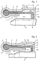
- FIG. 1 shows an embodiment of a brush seal, generally designated 1, the two rooms with different pressures P1, P2 between a rotationally symmetrical indicated with its peripheral surface U.
- Rotor 2 and a stator not shown, e.g. one housing, one Gas turbine, e.g. of an aircraft engine, seals.
- the pressure P1 is higher than the pressure P2.
- the brush seal 1 is in Fig. 1 without pressurization shown.
- the free ends of the bristles or bristle pack 3 of the Brush seal 1 run against the peripheral surface U of the rotor 2.
- the bristles 3 are wound around a core 4 and held in a retaining ring 5 or positioned.
- the type of attachment of the bristles 3 is not important in the present case and can be done in other ways.
- the bristle pack or the bristles 3 have shaft sections 6 and angled sections Bristle sections 7. Extend in the present installation position the shaft sections 6 of the bristles 3 in the axial direction of the gas turbine.
- the Angle between the shaft sections 6 and the angled bristle sections In the present case, 7 is approximately 90 °, so that the angled bristle section 7 lies essentially in a radial plane.
- the retaining ring 5 is in one positioned overall with 8 housing of the brush seal 1.
- the housing 8 comprises a support plate 9 with a substantially longitudinal section extending in the direction of the shaft section 6 of the bristles 3 10 and an angled support section 11.
- the shape of the Housing 8, the support plate 9 and a front plate, not described in detail influence the function of the brush seal 1 and are depending on Use case designed.
- the free ends of the angled bristle sections 7 are in contact via the support section 11 of the support plate 9 the peripheral surface U of the rotor 2 before.
- a bending space 13 is provided between the bristles 3 and the support plate 9.
- the bending space 13 extends up to the transition between the longitudinal section 10 and the support section 11 of the support plate 9 forming end edge 14.
- the shaft sections 6 of the bristles 3 can in the Bending free space 13 are deflected so as to be relatively rigid to keep short, angled bristle sections 7 within reasonable limits and depending on the length L of the deflectable part of the shaft sections To be able to adjust 6 of the bristles 3.
- the length L of the bending space 13 starting from the support section 11 of the support plate 9 may well continue extend in the direction of the retaining ring 5 of the bristles 3 than the present one Embodiment is shown.
- the support plate 9 has a gap 12.
- the size of the gap 12 becomes dependent of the pressure difference applied to the brush seal 1 during operation set so that it is ensured that the shaft portions 6 of the Bristles 3 with pressure difference not under pressure in the shaft sections 6 in a forced position against the support section 11 or its inner surface can be pressed.
- Fig. 2 shows a schematic side view of a brush seal, in which the Bristles 3 due to an increase in pressure in the room higher pressure P1 or as a result a rotor / housing displacement are deflected.
- the pressure P3 in the bending space 13 is higher than the pressure P1 in the space Pressure.
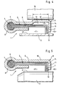
- FIG. 3 shows another installation position of a brush seal 1, in which the longitudinal section 10 of the support plate 9 and the shaft sections 6 of the Bristles 3 extend essentially in a radial plane of the gas turbine and the free ends of the angled bristle sections 7 against a radially aligned face sealing surface 15 of the rotor 2 run.
- the support section 11 of the support plate 9 and the angled bristle sections 7 of the bristles 3 run in this embodiment essentially in the axial direction Gas turbine.
- the described pressure compensation movement of the bristles 3 through the previously set size of the gap 12 when the pressure difference changes between the higher pressure space P1 and the lower space Pressure P2 is done in the same way.
- the brush seal 1 with angled bristle sections 7 can be used in all use their designs in different installation positions and is both suitable for stationary gas turbines as well as for aircraft engines. by virtue of the angled one that extends generally in the radial direction Bristle sections 7, the brush seal 1 in both directions of rotation of the rotor 2 are operated.
- Fig. 4 shows an alternative installation position of an embodiment of the invention Brush seal 1 against a circumferential surface U 'of a radial rotor 2 arranged on the outside seals, for example a cylindrical one in the case of a roller Ring component can be. 4, the conditions are without pressurization shown.
- the brush seal 1 is on an inside Stator 16 arranged so that the angled bristle sections 7 in essentially in the radial direction to the outside or - when the angled Bristle sections 7 in the direction of rotation of the rotor - at an angle between Extend 0 ° and 70 ° to the radial direction.
- the setting described above the gap 12 takes place in a corresponding manner.
- Brush seal 1 are the angled bristle sections 7 at an angle of about 45 ° to the radial direction in the direction of rotation of the rotor.
- a Deflection of the rotor 2 is consequently the shaft sections 6 of the Bristles 3 twisted, a so-called channel formation for through the bristle pack 3 flowing air is avoided.
- due to the torsion generates large restoring force, so that the angled bristle sections 7 after the deflection and not on the support section 11 of the Support plate 9 stick. Due to the effects described, a achieve a significant improvement in the sealing effect of the brush seal 1.
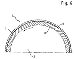
- Fig. 6 shows a schematic front view in section, in which half of the Brush seal 1 according to the embodiment of FIG. 5 is shown.
- the support section 11 of the support plate 9 is omitted or only hinted at.
- the angled bristle sections 7 in the direction of the direction of rotation, which is marked with an arrow is set at an angle of approximately 45 °.
- the angled bristle sections 7 are underneath Torsion of the shaft sections 6. This measure will result in the one described above Channel formation avoided. There is also a large restoring force due to the torsion.
- the angled bristle sections 7 in one another Angles from 0 ° to 70 ° with respect to the radial direction in the direction of rotation of the rotor be employed. With such a position, the shaft sections 6 the bristles 3 with radial deflection of the angled bristle sections 7, e.g. due to a deflection of the rotor 2, twisted and thereby unfold a large restoring force, so that here too the angled bristle sections 7 not deteriorating the sealing effect on the support section 11 of the support plate 9 stick.
- the design of the brush seal 1 with employed, angled bristle sections 7 can both with and without bending space 13. In a version with Bending free space 13 therefore occurs when the rotor 2 is deflected of bending and torsion of the shaft sections 6 of the bristles 3.
Description
Die Erfindung betrifft eine Bürstendichtung mit abgewinkelten Borsten, zum Abdichten eines Rotors gegen einen Stator umfassend eine Stützplatte mit einem Längsabschnitt und einem dazu abgewinkelten Stützabschnitt und Borsten mit Schaftabschnitten und dazu abgewinkelten Borstenabschnitten, deren Enden gegen die Dichtfläche des Rotors laufen.The invention relates to a brush seal with angled bristles, for Sealing a rotor against a stator comprising a support plate a longitudinal section and an angled support section and bristles with shaft sections and angled bristle sections whose Run the ends against the sealing surface of the rotor.
Der Einsatz von Bürstendichtungen bei Gasturbinen hat sich gegenüber anderen Dichtungsbauarten, wie z.B. Lippen- oder Labyrinthdichtungen, aufgrund verschiedener Vorteile bewährt.The use of brush seals in gas turbines has been different from others Seal types, e.g. Lip or labyrinth seals, due to proven various advantages.
Aus der DE 196 18 475 A 1 ist eine Bürstendichtung bekannt, deren Borsten zur Verringerung der radialen Baulänge abgewinkelt sind. Um die höhere Steifigkeit der kurzen, abgewinkelten Borstenabschnitte in vertretbaren Grenzen zu halten, ist ein im Bereich der Schaftabschnitte der Borsten liegender Anschlag vorgesehen, der als Biegekante wirkt, wenn die elastischen Borsten infolge einer Exzentrizität des Rotors ausgelenkt werden. Auf diese Weise läßt sich die Steifigkeit der Borsten ohne unzulässig großen, radialen Bauraum einstellen.From DE 196 18 475 A1 a brush seal is known, the bristles are angled to reduce the radial overall length. For the higher rigidity the short, angled bristle sections within reasonable limits to hold is a stop located in the area of the shaft sections of the bristles provided that acts as a bending edge when the elastic bristles result an eccentricity of the rotor can be deflected. That way the stiffness of the bristles can be adjusted without an impermissibly large radial installation space.
Als problematisch hat sich bei derartigen Bürstendichtungen jedoch die auftretende Leckage erwiesen. Diese setzt sich zum einen aus einer Primärleckage durch den Ringspalt zwischen Rotor und dem Borstenpaket und zum anderen aus einer "Bypass-Luftmenge" zusammen, die über den Biegefreiraum zwischen der Stützplatte und dem Borstenpaket strömt.However, the problem that arises with such brush seals has been problematic Leakage proven. On the one hand, this consists of a primary leak through the annular gap between the rotor and the bristle pack and to the other from a "bypass air volume", which over the bending space between the support plate and the bristle pack flows.
Die Aufgabe der vorliegenden Erfindung besteht darin, eine Bürstendichtung mit abgewinkelten Borsten so zu verbessern, daß eine möglichst optimale Dichtwirkung erzielt wird, ohne daß der sog. "hang up-Effekt" auftritt, wonach das Borstenpaket bei anliegendem Differenzdruck gegen die Stützplatte gedrückt wird und infolge der Reibungskraft daran haften bleibt.The object of the present invention is a brush seal to improve with angled bristles so that the best possible Sealing effect is achieved without the so-called "hang up effect", after which the bristle pack is pressed against the support plate when differential pressure is present will stick to it due to the frictional force.
Die Lösung der Aufgabe ist erfindungsgemäß dadurch gekennzeichnet, daß zwischen den Schaftabschnitten der Borsten und der Stützplatte ein Biegefreiraum vorgesehen ist und zwischen den abgewinkelten Borstenabschnitten und dem Stützabschnitt der Stützplatte über dessen gesamte Länge ein Spalt vorhanden ist, der sich bei anliegendem Differenzdruck schließt.The solution to the problem is characterized in that there is a bending space between the shank sections of the bristles and the support plate is provided and between the angled bristle sections and the support section of the support plate has a gap over its entire length which closes when differential pressure is present.
Der Vorteil besteht darin, daß durch die je nach Differenzdruck wählbare Einstellung des Spaltes der Druck im Biegefreiraum dem Druck vor der Bürstendichtung entspricht. Das bedeutet, daß nahezu der gesamte Druckabfall über das abgwinkelte Borstenpaket bzw. die abgewinkelten Borstenabschnitte erfolgt. Das Borstenpaket wird bei Druckbeaufschlagung nicht in der Weise in eine Zwangslage gebracht, daß es unter großem axialen Druck an den Stützabschnitt gepreßt wird, seine Elastizität verliert und nach einer Auslenkung des Rotors dort haften bleibt. Bei normalem Betrieb unter Druckbeaufschlagung, d.h. konstanten Betriebsbedingungen, legen sich die abgewinkelten Borstenabschnitte wenigstens stellen- bzw. abschnittsweise an dem Stützabschnitt der Stützplatte unter Schließung des Spalts an.The advantage is that the setting that can be selected depending on the differential pressure the gap, the pressure in the bending space the pressure in front of the brush seal equivalent. That means almost all of the pressure drop across the angled bristle pack or the angled bristle sections takes place. The bristle pack is not in the way when pressurized brought a constraint that it is under great axial pressure on the support section is pressed, loses its elasticity and after a deflection of the Rotors sticks there. In normal operation under pressure, i.e. constant operating conditions, the angled bristle sections lay down at least in places or sections on the support section the support plate while closing the gap.
Bevorzugt ist der Spalt so eingestellt, daß in den Schaftabschnitten der Borsten bei anliegendem Differenzdruck keine Druckbelastungen bzw. - spannungen vorliegen. Vielmehr wird der Differenzdruck als Zugkraft in den Schaftabschnitten der Borsten aufgenommen. Auf diese Weise entspricht der Druck im Biegefreiraum dem größeren Druck vor der Bürstendichtung, so daß die Schaftabschnitte der Borsten keine Druckbelastung erfahren und bei einer Änderung des Druckniveaus eine quasi automatische Rückstellwirkung zeigen. Bei einer Druckverringerung drückt der noch kurzzeitig höhere Druck im Biegefreiraum die elastischen Borsten in Richtung auf die Dichtfläche des Rotors, d.h. im allgemeinen radial nach innen. Umgekehrt werden die Schaftabschnitte der elastischen Borsten bei einem Druckanstieg zunächst von der Dichtfläche des Rotors weg angehoben, d.h. im allgemeinen radial nach außen, bis sich ein Druckausgleich einstellt.The gap is preferably set such that in the shaft sections of the bristles no pressure loads or - when differential pressure is present tensions are present. Rather, the differential pressure as a tensile force in the Shank sections of the bristles added. In this way, the Pressure in the bending space the greater pressure in front of the brush seal, so that the shaft sections of the bristles do not experience any pressure load and at one Changes in the pressure level show a quasi-automatic reset effect. When the pressure is reduced, the pressure in the bending space, which is still higher for a short time, presses the elastic bristles towards the sealing surface of the rotor, i.e. generally radially inward. The shaft sections are reversed the elastic bristles when the pressure rises initially from the sealing surface of the rotor, i.e. generally radially outward until a Pressure equalization.
Bevorzugt erstreckt sich der Biegefreiraum bis zu einer Endkante des Längsabschnitts der Stützplatte.The bending free space preferably extends to an end edge of the longitudinal section the support plate.
Die Lösung der Aufgabe ist alternativ dadurch gekennzeichnet, daß die abgewinkelten Borstenabschnitte in einem Winkel in Richtung des Rotordrehsinns angestellt sind, wobei der Winkel zwischen 0 ° und 70° und höchst bevorzugt zwischen 40 ° und 50 ° beträgt.The solution to the problem is alternatively characterized in that the angled Bristle sections at an angle in the direction of the direction of rotation of the rotor are employed, the angle between 0 ° and 70 ° and highly preferred is between 40 ° and 50 °.
Durch das Anstellen der Borsten in Drehrichtung des Rotors wird die Dichtwirkung verbessert, da die durch das Borstenpaket strömende Luft durch die schrägstehenden Borsten umgelenkt wird und damit die bei nicht angestellten Borsten vorkommende sog. "jet-through"-Strömungsform, d.h. Kanalbildung zwischen den Borstenreihen, vermieden wird. Zudem wird bei Auslenkungen des Rotors durch die Torsion der Schaftabschnitte der Borsten eine große Rückstellkraft erzeugt, wodurch das Haften der abgewinkelten Borstenabschnitte an der Stützplatte kaum noch auftritt.By placing the bristles in the direction of rotation of the rotor, the sealing effect improved because the air flowing through the bristle pack through the oblique bristles is deflected and thus those of non-employed Bristle occurring so-called "jet-through" flow form, i.e. channeling between the rows of bristles is avoided. In addition, when there are deflections of the rotor by the torsion of the shaft sections of the bristles a large one Restoring force generated, causing the angled bristle sections to stick hardly occurs on the support plate.
Bevorzugt ist zwischen den Schaftabschnitten der Borsten und der Stützplatte ein Biegefreiraum vorgesehen, so daß die Rückstellwirkung der Borsten bei sich ändernden Drücken und Auslenkungen des Rotors überlagert durch Biegung und Torsion erzeugt wird.It is preferred between the shank sections of the bristles and the support plate a bending space is provided so that the restoring effect of the bristles changing pressures and deflections of the rotor overlaid by bending and torsion is generated.
Es kann des weiteren vorteilhaft sein, daß die Schaftabschnitte der Borsten länger als die abgewinkelten Borstenabschnitte sind, damit das Borstenpaket unter Ausnutzung der Rückstellwirkung der elastischen Borsten nicht zu steif wird. It can furthermore be advantageous for the shank sections of the bristles longer than the angled bristle sections so the bristle pack taking advantage of the resilience of the elastic bristles not too stiff becomes.
Weitere Ausgestaltungen der Erfindung sind in den Unteransprüchen beschrieben.Further refinements of the invention are described in the subclaims.
Im folgenden wird die Erfindung anhand von Ausführungsbeispielen unter Bezugnahme auf eine Zeichnung näher erläutert. Es zeigt:
- Fig. 1
- eine schematische Schnittansicht eines Ausführungsbeispiels der erfindungsgemäßen Bürstendichtung ohne Druckbeaufschlagung,
- Fig. 2
- eine schematische Schnittansicht eines weiteren Ausführungsbeispiels der Bürstendichtung unter Druckbeaufschlagung im ausgelenkten Zustand der Borsten infolge eines Druckanstiegs oder einer Rotor-/Gehäuseauslenkung,
- Fig. 3
- eine schematische Schnittansicht einer Einbaulage eines weiteren Ausführungsbeispiels der erfindungsgemäßen Bürstendichtung bei einem Rotor mit einer stirnseitigen Dichtfläche,
- Fig. 4
- eine schematische Schnittansicht einer alternativen Einbaulage eines weiteren Ausführungsbeispiels der erfindungsgemäßen Bürsgtendichtung bei einem Außen-Rotor,
- Fig.5
- eine schematische Schnittansicht eines weiteren alternativen Ausführungsbeispiels der erfindungsgemäßen Bürstendichtung mit in Rotordrehrichtung angestellten Borstenabschnitten und
- Fig. 6
- eine schematische Frontansicht im Schnitt des Ausführungsbeispiels der erfindungsgemäßen Bürstendichtung gemäß Fig. 5.
- Fig. 1
- 2 shows a schematic sectional view of an exemplary embodiment of the brush seal according to the invention without pressurization,
- Fig. 2
- 2 shows a schematic sectional view of a further exemplary embodiment of the brush seal under pressure in the deflected state of the bristles as a result of an increase in pressure or a rotor / housing deflection,
- Fig. 3
- 2 shows a schematic sectional view of an installation position of a further exemplary embodiment of the brush seal according to the invention in the case of a rotor with an end sealing surface,
- Fig. 4
- 2 shows a schematic sectional view of an alternative installation position of a further exemplary embodiment of the brush seal according to the invention in the case of an external rotor,
- Figure 5
- is a schematic sectional view of a further alternative embodiment of the brush seal according to the invention with bristle sections in the direction of rotation of the rotor and
- Fig. 6
- 5 shows a schematic front view in section of the exemplary embodiment of the brush seal according to the invention according to FIG. 5.
Fig. 1 zeigt ein Ausführungsbeispiel einer im ganzen mit 1 bezeichneten Bürstendichtung,
die zwei Räume mit unterschiedlichen Drucken P1, P2 zwischen
einem mit seiner Umfangsfläche U angedeuteten, rotationssymmetrischen
Rotor 2 und einem nicht dargestellten Stator, z.B. einem Gehäuse, einer
Gasturbine, wie z.B. eines Flugtriebwerks, abdichtet. Der Druck P1 ist größer
als der Druck P2. Die Bürstendichtung 1 ist in Fig. 1 ohne Druckbeaufschlagung
dargestellt. Die freien Enden der Borsten bzw. des Borstenpakets 3 der
Bürstendichtung 1 laufen gegen die Umfangsfläche U des Rotors 2. Die Borsten
3 sind um einen Kern 4 gewickelt und in einem Haltering 5 gehalten bzw.
positioniert. Die Befestigungsart der Borsten 3 ist vorliegend nicht von Bedeutung
und kann auch auf andere Weise erfolgen.1 shows an embodiment of a brush seal, generally designated 1,
the two rooms with different pressures P1, P2 between
a rotationally symmetrical indicated with its peripheral
Das Borstenpaket bzw. die Borsten 3 weisen Schaftabschnitte 6 und dazu abgewinkelte
Borstenabschnitte 7 auf. In der vorliegenden Einbaulage erstrecken
sich die Schaftabschnitte 6 der Borsten 3 in Axialrichtung der Gasturbine. Der
Winkel zwischen den Schaftabschnitten 6 und den abgewinkelten Borstenabschnitten
7 beträgt vorliegend etwa 90 °, so daß der abgewinkelte Borstenabschnitt
7 im wesentlichen in einer Radialebene liegt. Der Haltering 5 ist in einem
im ganzen mit 8 bezeichneten Gehäuse der Bürstendichtung 1 positioniert.
Das Gehäuse 8 umfaßt eine Stützplatte 9 mit einem sich im wesentlichen
in Richtung des Schaftabschnitts 6 der Borsten 3 erstreckenden Längsabschnitt
10 und einem dazu abgewinkelten Stützabschnitt 11. Die Form des
Gehäuses 8, der Stützplatte 9 sowie einer nicht näher beschriebenen Frontplatte
beeinflussen die Funktion der Bürstendichtung 1 und werden je nach
Anwendungsfall ausgelegt. Die freien Enden der abgewinkelten Borstenabschnitte
7 stehen über den Stützabschnitt 11 der Stützplatte 9 unter Berührung
der Umfangsfläche U des Rotors 2 vor.The bristle pack or the
Zwischen den Borsten 3 und der Stützplatte 9 ist ein Biegefreiraum 13 vorgesehen.
Der Biegefreiraum 13 erstreckt sich bis zu einer den Übergang zwischen
dem Längsabschnitt 10 und dem Stützabschnitt 11 der Stützplatte 9
bildenden Endkante 14. Die Schaftabschnitte 6 der Borsten 3 können in den
Biegefreiraum 13 ausgelenkt werden, um so die Steifigkeit der verhältnismäßig
kurzen, abgewinkelten Borstenabschnitte 7 in vertretbaren Grenzen zu halten
und in Abhängigkeit von der Länge L des ablenkbaren Teils der Schaftabschnitte
6 der Borsten 3 einstellen zu können. Die Länge L des Biegefreiraums 13
kann sich beginnend vom Stützabschnitt 11 der Stützplatte 9 durchaus weiter
in Richtung des Halterings 5 der Borsten 3 erstrecken als dieses im vorliegenden
Ausführungsbeispiel gezeigt ist.A
In der noch nicht mit Druck beaufschlagten Bürstendichtung 1 gemäß Fig. 1 ist
zwischen den abgewinkelten Borstenabschnitten 7 und dem Stützabschnitt 11
der Stützplatte 9 ein Spalt 12 vorhanden. Die Größe des Spalts 12 wird in Abhängigkeit
von der im Betrieb an der Bürstendichtung 1 anliegenden Druckdifferenz
so eingestellt, daß gewährleistet ist, daß die Schaftabschnitte 6 der
Borsten 3 bei anliegender Druckdifferenz nicht unter Einbringung von Druckspannungen
in den Schaftabschnitten 6 in einer Zwangslage gegen den Stützabschnitt
11 bzw. dessen Innenfläche gedrückt werden.In the
Durch die Einstellung der Größe des Spalts 12 zwischen den abgewinkelten
Borstenabschnitten 7 und dem Stützabschnitt 11 der Stützplatte 9 wird der
zwischen den Räumen P 1 und P2 anliegende Differenzdruck als Zugkraft in
den Schaftabschnitten 6 der Borsten 3 aufgenommen und der Spalt 12 nach
Druckbeaufschlagung geschlossen, wobei die Anpreßkraft der abgewinkelten
Borstenabschnitte 7 an den Stützabschnitt 11 infolge der Zugbeanspruchung
vergleichsweise gering ist. Dieses hat für die Dichtwirkung den Vorteil, daß die
daraus resultierende Reibungskraft zwischen den Borsten 3 der Stützplatte 9
ebenfalls gering ist und die Borsten 3 nach seitlichem Ausweichen infolge einer
Auslenkung des Rotors 2 nicht an dem Stützabschnitt 11 haften bleiben.By adjusting the size of the
Nach Druckbeaufschlagung stellt sich bei im wesentlichen konstanten Betriebsbedingungen
ein Druckgleichgewicht zwischen P1 und P3 ein, so daß
dieser nicht dargestellte Zustand jenem in Fig. 1 ohne Druckbeaufschlagung
von der Anordnung der einzelnen Elemente her ähnlich ist, jedoch mit dem
Unterschied, daß der Spalt 12 zwischen den abgewinkelten Borstenabschnitten
7 und dem Stützabschnitt 11 der Stützplatte 9 durch Anliegen der Borsten
geschlossen ist.After pressurization, the operating conditions are essentially constant
a pressure equilibrium between P1 and P3 so that
this not shown state that in Fig. 1 without pressurization
the arrangement of the individual elements is similar, but with the
Difference that the
Fig. 2 zeigt eine schematische Seitenansicht einer Bürstendichtung, bei der die
Borsten 3 infolge eines Druckanstiegs im Raum höheren Druckes P1 oder infolge
einer Rotor-/Gehäuseverschiebung ausgelenkt sind. Bei einer optimalen
Einstellung des Spaltes 12 zwischen den Borsten 3 und der Stützplatte 9 entspricht
der Druck P3 im Biegefreiraum 13 dem Druck P1 im Raum höheren
Druckes. Dieses hat nicht nur zur Folge, daß die Schaftabschnitte 6 der Borsten
3 bei anliegender Druckdifferenz ohne Druckbelastung verbleiben, sondern
auch daß der Ringspalt zwischen der Umfangsfläche U des Rotors 2 und
den freien Enden der Borsten 3, durch den die Primärleckage erfolgt, bei Änderungen
der Druckdifferenz automatisch optimal eingestellt wird.Fig. 2 shows a schematic side view of a brush seal, in which the
Bei einem in Fig. 2 dargestellten Druckanstieg im Raum höheren Druckes P1
werden die Borsten 3 durch den noch kurzzeitig niedrigeren Druck P3 im Biegefreiraum
13 nach oben, d.h. hier radial nach außen abgelenkt, bis sich ein
Druckausgleich einstellt. Im umgekehrten, nicht dargestellten Fall einer Druckverringerung
werden die Borsten 3 infolge des noch kurzzeitig höheren Druck
P3 im Biegefreiraum 13 nach unten, d.h. radial nach innen unter Verkleinerung
des Ringspalts zwischen Rotor 2 und Borsten 3 abgelenkt, bis sich ein Druckausgleich
eingestellt hat. Durch die Einstellung des Spalts 12 und die daraus
resultierenden Ausgleichsbewegungen infolge der Rückstellwirkung der Borsten
3 bei Änderung der Druckdifferenz tritt lediglich ein vergleichsweise
"weiches" Anstreifen der freien Enden der Borsten 3 an der Umfangsfläche U
des Rotors 2 auf. Hierdurch lassen sich die Standzeiten der Bürstendichtung 1
mit abgewinkelten Borsten 3 erhöhen und die Dichtwirkung verbessern. Darüber
hinaus verhindert die Rückstellwirkung ein Festkleben der Borsten 3 bzw.
der abgewinkelten Borstenabschnitte 7 an dem Stützabschnitt 11 der Stützplatte
9 bei hohen Differenzdrücken. With a pressure increase in the space of higher pressure P1 shown in FIG. 2
are the
In Fig. 3 ist eine andere Einbaulage einer Bürstendichtung 1 dargestellt, bei der
sich der Längsabschnitt 10 der Stützplatte 9 sowie die Schaftabschnitte 6 der
Borsten 3 im wesentlichen in einer Radialebene der Gasturbine erstrecken und
die freien Enden der abgewinkelten Borstenabschnitte 7 gegen eine radial ausgerichtete,
stirnseitige Dichtfläche 15 des Rotors 2 laufen. Der Stützabschnitt
11 der Stützplatte 9 und die abgewinkelten Borstenabschnitte 7 der Borsten 3
verlaufen bei dieser Ausgestaltung im wesentlichen in Axialrichtung der
Gasturbine. Die beschriebene Druckausgleichsbewegung der Borsten 3 durch
die zuvor eingestellte Größe des Spalts 12 bei einer Änderung der Druckdifferenz
zwischen dem Raum höheren Drucks P1 und dem Raum niedrigeren
Drucks P2 erfolgt in gleicher Weise.3 shows another installation position of a
Die Bürstendichtung 1 mit abgewinkelten Borstenabschnitten 7 läßt sich in all
ihren Ausgestaltungen in unterschiedlichen Einbaulagen einsetzen und ist sowohl
für stationäre Gasturbinen als auch für Flugtriebwerke geeignet. Aufgrund
der sich im allgemeinen im wesentlichen in Radialrichtung erstreckenden, abgewinkelten
Borstenabschnitte 7 kann die Bürstendichtung 1 in beiden Drehrichtungen
des Rotors 2 betrieben werden.The
Fig. 4 zeigt eine alternative Einbaulage eines Ausführungsbeispiels der erfindungsgemäßen
Bürstendichtung 1, die gegen eine Umfangsfläche U' eines radial
außen angeordneten Rotors 2 dichtet, der bspw. bei einer Walze ein zylindrisches
Ringbauteil sein kann. In Fig. 4 sind die Verhältnisse ohne Druckbeaufschlagung
dargestellt. Die Bürstendichtung 1 ist auf einem innenliegenden
Stator 16 angeordnet, so daß sich die abgewinkelten Borstenabschnitte 7 im
wesentlichen in Radialrichtung nach außen bzw. - bei einer Anstellung der abgewinkelten
Borstenabschnitte 7 im Rotordrehsinn - in einem Winkel zwischen
0 ° und 70 ° zur Radialrichtung erstrecken. Die oben beschriebene Einstellung
des Spalts 12 erfolgt hierbei in entsprechender Weise. Fig. 4 shows an alternative installation position of an embodiment of the
Bei dem in Fig. 5 dargestellten Ausführungsbeispiel der erfindungsgemäßen
Bürstendichtung 1 sind die abgewinkelten Borstenabschnitte 7 in einem Winkel
von etwa 45 ° zur Radialrichtung im Rotordrehsinn angestellt. Bei einer
Auslenkung des Rotors 2 werden infolgedessen die Schaftabschnitte 6 der
Borsten 3 tordiert, wobei eine sog. Kanalbildung für die durch das Borstenpaket
3 strömende Luft vermieden wird. Gleichzeitig wird infolge der Torsion eine
große Rückstellkraft erzeugt, so daß sich die abgewinkelten Borstenabschnitte
7 nach der Auslenkung zurückstellen und nicht an dem Stützabschnitt 11 der
Stützplatte 9 haften bleiben. Aufgrund der beschriebenen Effekte läßt sich eine
deutliche Verbesserung der Dichtwirkung der Bürstendichtung 1 erzielen.In the embodiment of the invention shown in Fig. 5
Fig. 6 zeigt eine schematische Frontansicht im Schnitt, in der eine Hälfte der
Bürstendichtung 1 gemäß dem Ausführungsbeispiel aus Fig. 5 dargestellt ist.
Zur besseren Übersicht ist der Stützabschnitt 11 der Stützplatte 9 weggelassen
bzw. lediglich angedeutet. Es ist zu erkennen, daß die abgewinkelten Borstenabschnitte
7 in Richtung des Rotordrehsinns, der mit einem Pfeil gekennzeichnet
ist, in einem Winkel von etwa 45 ° angestellt sind. Bei einer Auslenkung
des Rotors 2 heben sich die abgewinkelten Borstenabschnitte 7 unter
Torsion der Schaftabschnitte 6 an. Durch diese Maßnahme wird die oben beschriebene
Kanalbildung vermieden. Zudem stellt sich eine große Rückstellkraft
infolge der Torsion ein.Fig. 6 shows a schematic front view in section, in which half of the
In einem weiteren, nicht dargestellten Ausführungsbeispiel der Bürstendichtung
1 können die abgewinkelten Borstenabschnitte 7 in einem in einem anderen
Winkel von 0 ° bis 70 ° gegenüber der Radialrichtung im Rotordrehsinn
angestellt sein. Bei einer derartigen Anstellung werden die Schaftabschnitte 6
der Borsten 3 bei radialem Ausweichen der abgewinkelten Borstenabschnitte
7, z.B. infolge einer Auslenkung des Rotors 2, tordiert und entfalten dadurch
eine große Rückstellkraft, so daß auch hier die abgewinkelten Borstenabschnitte
7 nicht unter Verschlechterung der Dichtwirkung an dem Stützabschnitt
11 der Stützplatte 9 haften bleiben. Die Ausgestaltung der Bürstendichtung
1 mit angestellten, abgewinkelten Borstenabschnitten 7 kann sowohl
mit als auch ohne Biegefreiraum 13 ausgeführt sein. Bei einer Ausführung mit
Biegefreiraum 13 tritt mithin bei einer Auslenkung des Rotors 2 eine Überlagerung
von Biegung und Torsion der Schaftabschnitte 6 der Borsten 3 auf.In a further embodiment of the brush seal, not shown
1, the angled bristle
Claims (10)
- A brush seal with angled bristles for sealing a rotor (2) against a stator comprising a base plate (9) with a longitudinal section (10) and a base section (11) and bristles (3) having shaft sections (6) and bristle sections (7) angled in relation thereto, the ends of which run against the sealing surface of the rotor (2),
characterised in that
provided between the shaft sections (6) of the bristles (3) and the base plate (9) is a bending space (13) and provided between the angled brush sections (7) and the base section (11) of the base plate (9) along the entire length of said base section (11) is a gap (12) which closes in the event of a pressure differential. - A brush seal in accordance with claim 1,
characterised in that
the gap (12) is set such that in the event of a pressure differential there is no pressure load in the shaft sections (6) of the bristles (3). - A brush seal in accordance with claim 1 or 2,
characterised in that
the bending space (13) extends to the end edge (!4) of the longitudinal section (10) of the base plate (9). - A brush seal with angled bristles for sealing a rotor (2) against a stator comprising a base plate (9) with a longitudinal section (10) and a base section (11) and bristles (3) with shaft sections (6) and bristle sections (7) angled in relation thereto, the ends of which run against the sealing surface of the rotor (2),
characterised in that
the angled bristle sections (7) are set at an angle in the direction of the direction of rotation of the rotor. - A brush seal in accordance with claim 4,
characterised in that
the angle is between 0° and 70°. - A brush seal in accordance with claim 4 or 5,
characterised in that
provided between the shaft sections (6) of the bristles (3) and the base plate (9) is a bending space (13). - A brush seal in accordance with one or more of the preceding claims,
characterised in that
the shaft sections (6) of the bristles (3) are longer than the angled bristle sections (7). - A brush seal in accordance with one or more of the preceding claims,
characterised in that
the free ends of the bristles (3) form a seal against an internal rotor (2). - A brush seal in accordance with one or more of claims 1 to 7,
characterised in that
the free ends of the bristles (3) form a seal against an external rotor (2). - A brush seal in accordance with claim 9,
characterised in that
the rotor (2) is a cylindrical annular body.
Applications Claiming Priority (2)
| Application Number | Priority Date | Filing Date | Title |
|---|---|---|---|
| DE19855742 | 1998-12-03 | ||
| DE19855742A DE19855742C1 (en) | 1998-12-03 | 1998-12-03 | Brush seal with angled bristles |
Publications (2)
| Publication Number | Publication Date |
|---|---|
| EP1006301A1 EP1006301A1 (en) | 2000-06-07 |
| EP1006301B1 true EP1006301B1 (en) | 2004-05-12 |
Family
ID=7889814
Family Applications (1)
| Application Number | Title | Priority Date | Filing Date |
|---|---|---|---|
| EP99122735A Expired - Lifetime EP1006301B1 (en) | 1998-12-03 | 1999-11-16 | Brush seal with angled bristles |
Country Status (6)
| Country | Link |
|---|---|
| US (1) | US6352263B1 (en) |
| EP (1) | EP1006301B1 (en) |
| JP (1) | JP4616435B2 (en) |
| CA (1) | CA2291467C (en) |
| DE (2) | DE19855742C1 (en) |
| ES (1) | ES2219981T3 (en) |
Families Citing this family (32)
| Publication number | Priority date | Publication date | Assignee | Title |
|---|---|---|---|---|
| US6416647B1 (en) * | 1998-04-21 | 2002-07-09 | Applied Materials, Inc. | Electro-chemical deposition cell for face-up processing of single semiconductor substrates |
| US6258220B1 (en) * | 1998-11-30 | 2001-07-10 | Applied Materials, Inc. | Electro-chemical deposition system |
| DE19962316C2 (en) * | 1999-12-23 | 2002-07-18 | Mtu Aero Engines Gmbh | brush seal |
| DE10017643B4 (en) * | 2000-04-08 | 2005-10-20 | Mtu Aero Engines Gmbh | Seal in non-hermetic design |
| US20100007093A1 (en) * | 2001-02-23 | 2010-01-14 | Grondahl Clayton M | Seal Assembly and Rotary Machine Containing Such Seal |
| US6644667B2 (en) * | 2001-02-23 | 2003-11-11 | Cmg Tech, Llc | Seal assembly and rotary machine containing such seal |
| US7578509B2 (en) * | 2001-02-23 | 2009-08-25 | Cmg Tech, Llc | Seal assembly and rotary machine containing such seal |
| JP4944312B2 (en) * | 2001-06-29 | 2012-05-30 | イーグル工業株式会社 | Brush seal device |
| JP3611811B2 (en) | 2001-08-22 | 2005-01-19 | ティー・アンド・エム株式会社 | SEALING MATERIAL FOR HIGH-SPEED ROTATING BODY, USE THEREOF, AND DEVELOPING DEVICE |
| GB0127643D0 (en) | 2001-11-17 | 2002-01-09 | Cross Mfg 1938 Company Ltd | A brush seal element |
| DE10163804B4 (en) * | 2001-12-22 | 2005-07-07 | Mtu Aero Engines Gmbh | brush seal |
| US20040118694A1 (en) * | 2002-12-19 | 2004-06-24 | Applied Materials, Inc. | Multi-chemistry electrochemical processing system |
| US6679500B1 (en) | 2002-09-25 | 2004-01-20 | Alstom (Switzerland) Ltd | Coal pulverizer brush seal assembly |
| US8199453B2 (en) | 2003-03-17 | 2012-06-12 | Illinois Tool Works Inc. | Shaft current control brush ring assembly |
| US20050077182A1 (en) * | 2003-10-10 | 2005-04-14 | Applied Materials, Inc. | Volume measurement apparatus and method |
| FR2865012B1 (en) * | 2004-01-12 | 2006-03-17 | Snecma Moteurs | SEALING DEVICE FOR TURBOMACHINE HIGH-PRESSURE TURBINE |
| GB2410533B (en) * | 2004-01-28 | 2006-02-08 | Rolls Royce Plc | Sealing arrangement |
| US20070278093A1 (en) * | 2006-06-02 | 2007-12-06 | Barnard Michael P | Electrical conductive contact ring for electroplating or electrodeposition |
| DE102006049634A1 (en) | 2006-10-20 | 2008-04-24 | Mtu Aero Engines Gmbh | sealing arrangement |
| US8596973B2 (en) * | 2009-12-07 | 2013-12-03 | Cmg Tech, Llc | Leaf seal assembly including polymer member and rotary machine containing such seal assembly |
| US8317464B2 (en) * | 2010-02-16 | 2012-11-27 | General Electric Company | Reverse flow tolerant spring activated brush seal |
| US9255486B2 (en) | 2011-03-28 | 2016-02-09 | General Electric Company | Rotating brush seal |
| US9121297B2 (en) | 2011-03-28 | 2015-09-01 | General Electric Company | Rotating brush seal |
| US8632075B2 (en) * | 2011-08-08 | 2014-01-21 | General Electric Company | Seal assembly and method for flowing hot gas in a turbine |
| GB201202104D0 (en) * | 2012-02-08 | 2012-03-21 | Rolls Royce Plc | Leaf seal |
| US9540942B2 (en) | 2012-04-13 | 2017-01-10 | General Electric Company | Shaft sealing system for steam turbines |
| US9587505B2 (en) | 2013-12-05 | 2017-03-07 | General Electric Company | L brush seal for turbomachinery application |
| US9322287B2 (en) * | 2014-06-03 | 2016-04-26 | General Electric Company | Brush seal for turbine |
| US11035470B2 (en) | 2018-04-05 | 2021-06-15 | Raytheon Technologies Corporation | Multi-plane brush seal |
| US10662797B2 (en) | 2018-04-05 | 2020-05-26 | Raytheon Technologies Corporation | Multi-plane brush seal |
| US11261971B2 (en) * | 2019-11-11 | 2022-03-01 | Raytheon Technologies Corporation | Double angled brush seal |
| CN114635757B (en) * | 2022-02-23 | 2023-12-12 | 潍柴动力股份有限公司 | Rotor sealing device |
Family Cites Families (10)
| Publication number | Priority date | Publication date | Assignee | Title |
|---|---|---|---|---|
| JPS5717U (en) * | 1980-05-30 | 1982-01-05 | ||
| GB2140674A (en) * | 1983-04-27 | 1984-12-05 | Schlegel | Angled bristle strips and methods of manufacture |
| US4779904A (en) * | 1986-10-31 | 1988-10-25 | Rich Christopher K | Couplings for connecting vehicle exhaust tail pipes to exhaust conduits for removing vehicle exhaust gases |
| GB2212228B (en) * | 1987-11-13 | 1991-08-07 | Rolls Royce Plc | Enhanced performance brush seals |
| US5110033A (en) * | 1991-02-21 | 1992-05-05 | United Technologies Corporation | Segmented brush seal |
| WO1997014897A2 (en) * | 1995-10-05 | 1997-04-24 | Eg & G Sealol, Inc. | A brush seal with a flexible front plate |
| DE19613510C1 (en) * | 1996-04-04 | 1997-04-24 | Mtu Muenchen Gmbh | Brush seal for sealing ring-shaped gap between rotor-stator arrangement |
| DE19618475B4 (en) * | 1996-05-08 | 2005-10-20 | Mtu Aero Engines Gmbh | brush seal |
| JP3382802B2 (en) * | 1997-01-13 | 2003-03-04 | 三菱重工業株式会社 | Shaft seal |
| DE19712088C2 (en) * | 1997-03-22 | 1999-06-24 | Mtu Muenchen Gmbh | Brush seal with bristles inclined in the circumferential direction |
-
1998
- 1998-12-03 DE DE19855742A patent/DE19855742C1/en not_active Expired - Fee Related
-
1999
- 1999-11-16 EP EP99122735A patent/EP1006301B1/en not_active Expired - Lifetime
- 1999-11-16 DE DE59909465T patent/DE59909465D1/en not_active Expired - Lifetime
- 1999-11-16 ES ES99122735T patent/ES2219981T3/en not_active Expired - Lifetime
- 1999-12-02 CA CA002291467A patent/CA2291467C/en not_active Expired - Fee Related
- 1999-12-03 US US09/454,193 patent/US6352263B1/en not_active Expired - Lifetime
- 1999-12-03 JP JP34514899A patent/JP4616435B2/en not_active Expired - Fee Related
Also Published As
| Publication number | Publication date |
|---|---|
| EP1006301A1 (en) | 2000-06-07 |
| ES2219981T3 (en) | 2004-12-01 |
| JP4616435B2 (en) | 2011-01-19 |
| DE19855742C1 (en) | 2000-09-14 |
| US6352263B1 (en) | 2002-03-05 |
| JP2000170922A (en) | 2000-06-23 |
| DE59909465D1 (en) | 2004-06-17 |
| CA2291467A1 (en) | 2000-06-03 |
| CA2291467C (en) | 2008-07-22 |
Similar Documents
| Publication | Publication Date | Title |
|---|---|---|
| EP1006301B1 (en) | Brush seal with angled bristles | |
| DE19962316C2 (en) | brush seal | |
| DE69915587T2 (en) | INTERCHANGEABLE BRIDGE SEAL | |
| DE3836474C2 (en) | Brush seal | |
| DE60116455T2 (en) | seal means | |
| DE69828255T2 (en) | SEAL STRUCTURE FOR GAS TURBINES | |
| EP3315728B1 (en) | Damped guide vane bearing | |
| EP1146266A2 (en) | Brush seal | |
| EP0981703A1 (en) | Brush-hair seal | |
| DE102011052347A1 (en) | Floating packing ring arrangement | |
| EP2271827B1 (en) | Turbo machine with stroke-compensating piston | |
| DE2556992B1 (en) | Shaft seal | |
| DE102012102625A1 (en) | Rotary brush seal | |
| EP3330490A1 (en) | Turbo machines seal arrangement | |
| EP1224381B1 (en) | Device for compensating axial thrust in a turbomachine | |
| DE4425344C2 (en) | Rotary vane with at least one axial needle slewing ring as a rotatable bearing element | |
| DE2519689A1 (en) | SEAL FOR A TURBO MACHINE | |
| DE2752445C2 (en) | Flexible joint washer for shaft couplings | |
| DE102020209287A1 (en) | Seal arrangement with great play | |
| EP1207324B1 (en) | Sealing between two elements of a rotating unit, method for making a sealing joint | |
| DE2844906C2 (en) | Sealing ring, especially for hydraulically operated cylinder pistons or piston rods | |
| DE102004047206B4 (en) | sealing arrangement | |
| DE10340825A1 (en) | Gas turbine with running gap control | |
| DE102014215623A1 (en) | Rolling, in particular needle roller bearings, for arrangement on a pivot of a variable guide vane of a turbomachine | |
| DE3321598A1 (en) | DOUBLE MECHANICAL SEAL |
Legal Events
| Date | Code | Title | Description |
|---|---|---|---|
| PUAI | Public reference made under article 153(3) epc to a published international application that has entered the european phase |
Free format text: ORIGINAL CODE: 0009012 |
|
| AK | Designated contracting states |
Kind code of ref document: A1 Designated state(s): CH DE ES FR GB IT LI |
|
| AX | Request for extension of the european patent |
Free format text: AL;LT;LV;MK;RO;SI |
|
| 17P | Request for examination filed |
Effective date: 20000726 |
|
| AKX | Designation fees paid |
Free format text: CH DE ES FR GB IT LI |
|
| RAP1 | Party data changed (applicant data changed or rights of an application transferred) |
Owner name: MTU AERO ENGINES GMBH |
|
| GRAP | Despatch of communication of intention to grant a patent |
Free format text: ORIGINAL CODE: EPIDOSNIGR1 |
|
| GRAS | Grant fee paid |
Free format text: ORIGINAL CODE: EPIDOSNIGR3 |
|
| GRAA | (expected) grant |
Free format text: ORIGINAL CODE: 0009210 |
|
| AK | Designated contracting states |
Kind code of ref document: B1 Designated state(s): CH DE ES FR GB IT LI |
|
| REG | Reference to a national code |
Ref country code: GB Ref legal event code: FG4D Free format text: NOT ENGLISH |
|
| REG | Reference to a national code |
Ref country code: CH Ref legal event code: EP |
|
| REG | Reference to a national code |
Ref country code: CH Ref legal event code: NV Representative=s name: ISLER & PEDRAZZINI AG |
|
| REF | Corresponds to: |
Ref document number: 59909465 Country of ref document: DE Date of ref document: 20040617 Kind code of ref document: P |
|
| GBT | Gb: translation of ep patent filed (gb section 77(6)(a)/1977) | ||
| REG | Reference to a national code |
Ref country code: ES Ref legal event code: FG2A Ref document number: 2219981 Country of ref document: ES Kind code of ref document: T3 |
|
| ET | Fr: translation filed | ||
| PLBE | No opposition filed within time limit |
Free format text: ORIGINAL CODE: 0009261 |
|
| STAA | Information on the status of an ep patent application or granted ep patent |
Free format text: STATUS: NO OPPOSITION FILED WITHIN TIME LIMIT |
|
| 26N | No opposition filed |
Effective date: 20050215 |
|
| REG | Reference to a national code |
Ref country code: CH Ref legal event code: PCAR Free format text: ISLER & PEDRAZZINI AG;POSTFACH 1772;8027 ZUERICH (CH) |
|
| PGFP | Annual fee paid to national office [announced via postgrant information from national office to epo] |
Ref country code: CH Payment date: 20121122 Year of fee payment: 14 |
|
| PGFP | Annual fee paid to national office [announced via postgrant information from national office to epo] |
Ref country code: ES Payment date: 20121127 Year of fee payment: 14 Ref country code: IT Payment date: 20121126 Year of fee payment: 14 |
|
| REG | Reference to a national code |
Ref country code: CH Ref legal event code: PL |
|
| PG25 | Lapsed in a contracting state [announced via postgrant information from national office to epo] |
Ref country code: LI Free format text: LAPSE BECAUSE OF NON-PAYMENT OF DUE FEES Effective date: 20131130 Ref country code: CH Free format text: LAPSE BECAUSE OF NON-PAYMENT OF DUE FEES Effective date: 20131130 |
|
| PG25 | Lapsed in a contracting state [announced via postgrant information from national office to epo] |
Ref country code: IT Free format text: LAPSE BECAUSE OF NON-PAYMENT OF DUE FEES Effective date: 20131116 |
|
| REG | Reference to a national code |
Ref country code: ES Ref legal event code: FD2A Effective date: 20150327 |
|
| PG25 | Lapsed in a contracting state [announced via postgrant information from national office to epo] |
Ref country code: ES Free format text: LAPSE BECAUSE OF NON-PAYMENT OF DUE FEES Effective date: 20131117 |
|
| REG | Reference to a national code |
Ref country code: FR Ref legal event code: PLFP Year of fee payment: 17 |
|
| PGFP | Annual fee paid to national office [announced via postgrant information from national office to epo] |
Ref country code: GB Payment date: 20151123 Year of fee payment: 17 Ref country code: DE Payment date: 20151119 Year of fee payment: 17 |
|
| PGFP | Annual fee paid to national office [announced via postgrant information from national office to epo] |
Ref country code: FR Payment date: 20151124 Year of fee payment: 17 |
|
| REG | Reference to a national code |
Ref country code: DE Ref legal event code: R119 Ref document number: 59909465 Country of ref document: DE |
|
| GBPC | Gb: european patent ceased through non-payment of renewal fee |
Effective date: 20161116 |
|
| REG | Reference to a national code |
Ref country code: FR Ref legal event code: ST Effective date: 20170731 |
|
| PG25 | Lapsed in a contracting state [announced via postgrant information from national office to epo] |
Ref country code: FR Free format text: LAPSE BECAUSE OF NON-PAYMENT OF DUE FEES Effective date: 20161130 |
|
| PG25 | Lapsed in a contracting state [announced via postgrant information from national office to epo] |
Ref country code: DE Free format text: LAPSE BECAUSE OF NON-PAYMENT OF DUE FEES Effective date: 20170601 Ref country code: GB Free format text: LAPSE BECAUSE OF NON-PAYMENT OF DUE FEES Effective date: 20161116 |