EP1006247B1 - Door lock system - Google Patents
Door lock system Download PDFInfo
- Publication number
- EP1006247B1 EP1006247B1 EP99306177A EP99306177A EP1006247B1 EP 1006247 B1 EP1006247 B1 EP 1006247B1 EP 99306177 A EP99306177 A EP 99306177A EP 99306177 A EP99306177 A EP 99306177A EP 1006247 B1 EP1006247 B1 EP 1006247B1
- Authority
- EP
- European Patent Office
- Prior art keywords
- door
- roller unit
- box body
- hook
- fixedly mounted
- Prior art date
- Legal status (The legal status is an assumption and is not a legal conclusion. Google has not performed a legal analysis and makes no representation as to the accuracy of the status listed.)
- Expired - Lifetime
Links
Images


Classifications
-
- H—ELECTRICITY
- H02—GENERATION; CONVERSION OR DISTRIBUTION OF ELECTRIC POWER
- H02B—BOARDS, SUBSTATIONS OR SWITCHING ARRANGEMENTS FOR THE SUPPLY OR DISTRIBUTION OF ELECTRIC POWER
- H02B1/00—Frameworks, boards, panels, desks, casings; Details of substations or switching arrangements
- H02B1/26—Casings; Parts thereof or accessories therefor
- H02B1/30—Cabinet-type casings; Parts thereof or accessories therefor
- H02B1/38—Hinged covers or doors
-
- E—FIXED CONSTRUCTIONS
- E05—LOCKS; KEYS; WINDOW OR DOOR FITTINGS; SAFES
- E05B—LOCKS; ACCESSORIES THEREFOR; HANDCUFFS
- E05B17/00—Accessories in connection with locks
- E05B17/0025—Devices for forcing the wing firmly against its seat or to initiate the opening of the wing
-
- E—FIXED CONSTRUCTIONS
- E05—LOCKS; KEYS; WINDOW OR DOOR FITTINGS; SAFES
- E05C—BOLTS OR FASTENING DEVICES FOR WINGS, SPECIALLY FOR DOORS OR WINDOWS
- E05C9/00—Arrangements of simultaneously actuated bolts or other securing devices at well-separated positions on the same wing
- E05C9/06—Arrangements of simultaneously actuated bolts or other securing devices at well-separated positions on the same wing with three or more sliding bars
- E05C9/063—Arrangements of simultaneously actuated bolts or other securing devices at well-separated positions on the same wing with three or more sliding bars extending along three or more sides of the wing or frame
-
- E—FIXED CONSTRUCTIONS
- E05—LOCKS; KEYS; WINDOW OR DOOR FITTINGS; SAFES
- E05C—BOLTS OR FASTENING DEVICES FOR WINGS, SPECIALLY FOR DOORS OR WINDOWS
- E05C9/00—Arrangements of simultaneously actuated bolts or other securing devices at well-separated positions on the same wing
- E05C9/10—Actuating mechanisms for bars
- E05C9/12—Actuating mechanisms for bars with rack and pinion mechanism
-
- E—FIXED CONSTRUCTIONS
- E05—LOCKS; KEYS; WINDOW OR DOOR FITTINGS; SAFES
- E05C—BOLTS OR FASTENING DEVICES FOR WINGS, SPECIALLY FOR DOORS OR WINDOWS
- E05C9/00—Arrangements of simultaneously actuated bolts or other securing devices at well-separated positions on the same wing
- E05C9/18—Details of fastening means or of fixed retaining means for the ends of bars
- E05C9/1825—Fastening means
- E05C9/1833—Fastening means performing sliding movements
- E05C9/185—Fastening means performing sliding movements parallel with actuating bar
Abstract
Description
- The present invention relates to a door lock system used in boxes and like containers for receiving therein electric instruments, communication instruments and like instruments.
- It has been known to dispose a packing member between an opening portion of a box body and a door for the purpose of sealing up, i.e., strictly cutting off the interior space of the box body from the outside space. In use, it is very difficult to uniformly compress the packing member over its entire length. Although it has been proposed to provide a plurality of clamping members along the packing member, this requires simultaneous clamping opertions of these clamping members. When some of these clamping members are ahead of the remaining ones in clamping operations, unclamped portions of the packing member corresponding to such remaining clamping members receive expelled parts of already clamped portions of the packing member, so that the unclamped portions of the packing member bulge out of their positions to prevent the door from being neatly closed, which prevents a latch of the clamping member from engaging with a corresponding socket member of the box body.
- In view of the above, another proposal has been made, in which: a plurality of rod members are connected with each other and provided in a peripheral portion of a door; a plurality of hook members are provided in a plurality of portions of the rod members; and, a plurality of roller units are fixedly mounted on a box body, wherein the hook members are engaged with the roller units to draw the roller units aside in closing and locking the door, so that a packing member disposed between the door and the box body is compressed therebetween. In this other proposal, however, a resilient force exerted by the thus compressed packing acts directly on the hook members and, therefore, on the rods on which the hook members are fixed, causing considerable flexing of the rods, resulting in permanent deformation of the rods after the door has been used several times. Such deformations often make it impossible to lock the door.
- WO-A-93/20315 discloses a bolt lock, in particular for control-cabinet doors. The lock comprises a flat-bar bolt which is mounted to move parallel to the edge of the door, preferably within the arc swing of the door, and which has at least one locking section. The lock further comprises a bolt holder, mounted on the door frame and designed to receive and hold the locking section of the bolt. The flat-bar bolt is twisted about its longitudinal axis over at least one part of its length in order to form the locking section and is twisted in such a way that the bolt surface in the twisted section is at an angle to the orientation of the bolt and so that a lug in the bolt holder extends out over the locking section at the same angle to the bolt, thus acting as a locking surface.
- Consequently, it is an object of the present invention to provide a door lock system, which is free from risk that in a locking operation of a door, vertical and horizontal rods on which hook members are fixedly mounted cause flexing, and that the hook members are subjected to shearing forces, or cause flexing, whereby a packing member is substantially uniformly compressed between the door and a box body.
- The above object of the present invention is accomplished by providing:
- A door lock system comprising:
- a box body on which a roller unit is fixedly mounted;
- a door on which a roller unit is fixedly mounted;
- a packing member disposed between the box body and the door;
- a right and a left vertical rod disposed along the right and the left side of the door, respectively, at least one of the vertical rods being provided with a rack portion engaging with a pinion gear of a handle member;
- an upper and a lower lateral rod disposed along the upper and the lower side of the door, respectively;
- a turning-point transmission unit, which is fixedly mounted in each of corner portions of the door and provided with a connecting bar through which the vertical rods and the lateral rods are connected with each other to form a chain-like assembly; and
- a hook member provided with a pair of hook portions, one of which is engaged with the roller unit of the box body to draw the roller unit aside, and the other of which is engaged with the roller unit of the door to draw the roller unit aside in closing operation of the door,
- wherein, when the handle member is pulled out and rotated, the hook member is moved to draw both the roller unit of the box body and the roller unit of the door aside so that the packing member is compressed between the door and the box body.
-
- By way of example only, a specific embodiment of the present invention will now be described, with reference to the accompanying drawings, in which:-
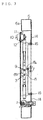
- Fig. 1 is a front view of a door lock system of an embodiment of the present invention;
- Fig. 2 is a cross-sectional view of the door lock system of the present invention in a condition in which a door is locked, taken along the line A-A of Fig. 1;
- Fig. 3 is a cross-sectional view of the door lock system of the present invention in a condition in which a door is unlocked, taken along the line A-A of Fig. 1;
- Fig. 4 is a cross-sectional view of the door lock system of the present invention, taken along the line B-B of Fig. 2; and
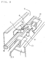
- Fig. 5 is an enlarged perspective view of a hook member in a condition in which the door is unlocked.
-
- Hereinbelow, the present invention will be described in detail with reference to the accompanying drawings.
- As is dear from Fig. 5, an embodiment of a door lock system of the present invention comprises: a
box body 6 on which aroller unit 7 provided with a rotatable roller element is fixedly mounted; a door 1 on which aroller unit 9 is fixedly mounted; and, apacking member 16 or seal (shown in Fig. 5) disposed between thebox body 6 and the door 1. - In the door lock assembly of the present invention, a right and a left
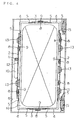
vertical rod 2 are disposed in the right and the left side of a door 1, respectively. On the other hand, an upper and a lowerlateral rod 3 are disposed in the upper and the lower side of a door 1, respectively. A turning-point transmission unit 4 is fixedly mounted in each of corner portions of the door 1, and provided with a connectingbar 5 through which thevertical rods 2 and thelateral rods 3 are connected with each other to form a chain-like assembly. - Of these
vertical rods 2, at least one 2 is provided with arack portion 12 engaging with apinion gear 11 of ahandle member 10. - A
hook member 8 is provided with a pair of hook portions 8a, 8b. In a closing operation of the door 1, one 8a of the hook portions 8a, 8b of thehook member 8 is engaged with theroller unit 7 of thebox body 6 to draw theroller unit 7 aside, and the other 8b of these hook portions 8a, 8b is engaged with aroller unit 9 of the door 1 to draw theroller unit 9 aside. When thehandle member 10 is pulled out and rotated, thehook member 8 is moved to draw both theroller unit 7 of thebox body 6 and theroller unit 9 of the door 1 aside so that thepacking member 16 is compressed between the door 1 and thebox body 6. - At this time, in the
hook member 8, its hook portion 8a has its drawing-cam oblique surface engaged with theroller unit 7 of thebox body 6. Since thevertical rods 2 and thelateral rods 3 are slidably moved in their longitudinal directions, the other hook portions 8b of thehook members 8 have their drawing-cam oblique surfaces engaged with theroller units 9 of the door 1. - In the embodiment shown in the drawings, all the right and the left
vertical rods 2 and the upper and the lowerlateral rods 3 are disposed in an inner surface of the door 1. On the other hand,handle member 10 is of a pull-out rotary type, and is embedded in a front surface of the door 1. A rotary shaft provided in a rear-end portion of thehandle member 10 is connected with apinion gear gear 11. Of thevertical rods 2, at least one 2 is provided with arack portion 12, which is constructed of a series of lateral openings or slots provided in thevertical rod 2 at predetermined intervals corresponding to the pitch of thepinion gear 11. - As shown in Fig. 4, the
vertical rods 2,lateral rods 3, turning-point transmission units 4 and the connectingbars 5 are connected in series with each other under tension without permitting any slackness. Thevertical rod 2, which is longer than thelateral rod 3, is inserted into aguide member 13 fixedly mounted on the inner surface of the door 1, so that thevertical rod 2 is limited in idle motion in horizontal plane, i.e. the lateral movement of the vertical rod in the horizontal plane is restricted. - A
flange portion 14 extends around the opening portion of afront wall portion 6a of thebox body 6 so as to surround the opening portion. As is dear from Fig. 2, theflange portion 14 is constructed of a front concave portion of thebox body 6, which concave portion is adjacent to thefront wall portion 6a. On the other hand, the door 1 assumes a flat box-like shape, which is opened in its inner surface and constructed of: a main front wall portion 1a, an outline of which is substantially the same size as that of an inner surface of the above-mentioned front concave portion of thebox body 6; and bent peripheral wall portions 1b contiguous to the individual side portions of the main front wall portion 1a. The door 1 is mounted on thebox body 6 through twohinge units 15 vertically arranged along the right edge surface of thebox body 6, and is supported thereby. Adhesively applied and fixed to an end portion of theflange portion 14 is apacking 16 made of rubber. It is also possible to provide thepacking 16 in the side of the door 1 alternatively or additionally. Each of thebox body 6 and the door 1 is constructed of steel plates. - As described above, in the present invention, in closing the door 1, it is possible for the
hook member 8 to have its hook portions 8a and 8b engaged with theroller unit 7 of thebox body 6 and theroller unit 9 of the door 1, respectively, to draw theseroller units packing 16 is substantially uniformly compressed over its entire length between thebox body 6 and the door 1. In addtion, as for thehook members 8 supported by thevertical rods 2 and thelateral rods 3, it is also possible to directly support thehook members 8 by the door 1. The above construction of the present invention ensures that the interior space of thebox body 6 is excellent in gas-tight and water-tight properties when closed by the door 1. - Further, the
hook member 8 is center-balanced by its hook portions 8a, 8b, so that shearing forces to which thevertical rods 2 and thelateral rods 3 are subjected are lessened. Consequently, it is possible to sufficiently lock the door 1 without causing any flexing of thevertical rods 2 and thelateral rods 3 and also without any fear that thehook members 8 are subjected to shearing forces and cause flexing.
Claims (1)
- A door lock system comprising:a box body (6) on which a roller unit (7) is fixedly mounted;a door (1) on which a roller unit (9) is fixedly mounted;a packing member disposed between said box body (6) and said door (1);a right and a left vertical rod (2) disposed in the right and the left side of said door (1), respectively, at least one of said vertical rods (2) being provided with a rack portion (12) engaging with a pinion gear (11) of a handle member (10);an upper and a lower lateral rod (3) disposed in the upper and the lower side of said door (1), respectively;a turning-point transmission unit (4), which is fixedly mounted in each of corner portions of said door (1) and provided with a connecting bar (5) through which said vertical rods (2) and said lateral rods (3) are connected with each other to form a chain-like assembly; anda hook member (8) provided with a pair of hook portions (8a, 8b), one (8a) of which is engaged with said roller unit (7) of said box body (6) to draw said roller unit (7) aside, and the other (8) of which is engaged with said roller unit (9) of said door (1) to draw said roller unit (9) aside in a closing operation of said door (1);wherein, when said handle member is pulled out and rotated, said hook member (8) is moved to draw both said roller unit (7) of said box body (6) and said roller unit (9) of said door (1) aside so that said packing member (16) is compressed between said door (1) and said box body (6).
Applications Claiming Priority (2)
| Application Number | Priority Date | Filing Date | Title |
|---|---|---|---|
| JP10343696A JP2983979B1 (en) | 1998-12-03 | 1998-12-03 | Door fastening lock device |
| JP34369698 | 1998-12-03 |
Publications (2)
| Publication Number | Publication Date |
|---|---|
| EP1006247A1 EP1006247A1 (en) | 2000-06-07 |
| EP1006247B1 true EP1006247B1 (en) | 2001-10-24 |
Family
ID=18363556
Family Applications (1)
| Application Number | Title | Priority Date | Filing Date |
|---|---|---|---|
| EP99306177A Expired - Lifetime EP1006247B1 (en) | 1998-12-03 | 1999-08-03 | Door lock system |
Country Status (4)
| Country | Link |
|---|---|
| EP (1) | EP1006247B1 (en) |
| JP (1) | JP2983979B1 (en) |
| AT (1) | ATE207572T1 (en) |
| DE (1) | DE69900386T2 (en) |
Cited By (2)
| Publication number | Priority date | Publication date | Assignee | Title |
|---|---|---|---|---|
| US8161601B2 (en) | 2005-12-09 | 2012-04-24 | Industrilas Ab | Hinge and latch mechanism |
| CN101379256B (en) * | 2005-12-09 | 2012-05-09 | 工业公司 | Control roller mechanism-activator |
Families Citing this family (4)
| Publication number | Priority date | Publication date | Assignee | Title |
|---|---|---|---|---|
| DE102005019209B4 (en) * | 2005-04-25 | 2007-07-12 | Dura Automotive Plettenberg Entwicklungs- Und Vertriebs Gmbh | Locking device for doors or flaps of motor vehicles |
| JP4732388B2 (en) * | 2007-03-22 | 2011-07-27 | 株式会社日立製作所 | Electronic equipment housing structure |
| JP5334610B2 (en) * | 2009-02-03 | 2013-11-06 | 株式会社クボタ | Air conditioner |
| CN111769456A (en) * | 2020-07-31 | 2020-10-13 | 江苏永特电力科技有限公司 | Dynamic reactive compensation capacitor cabinet |
Family Cites Families (3)
| Publication number | Priority date | Publication date | Assignee | Title |
|---|---|---|---|---|
| EP0261268B1 (en) * | 1986-09-25 | 1990-06-20 | Dieter Ramsauer | Locking device made of bars with locking bolts carried by the bar, the locking bolt especially containing two rollers |
| DE4210586C2 (en) * | 1992-03-31 | 1994-04-14 | Emka Beschlagteile | Rod lock for doors, especially for control cabinet doors |
| EP0847121A1 (en) * | 1996-12-09 | 1998-06-10 | Barat S.A. | Sealed, retractable cabinet for electric power distribution |
-
1998
- 1998-12-03 JP JP10343696A patent/JP2983979B1/en not_active Expired - Lifetime
-
1999
- 1999-08-03 AT AT99306177T patent/ATE207572T1/en not_active IP Right Cessation
- 1999-08-03 DE DE69900386T patent/DE69900386T2/en not_active Expired - Lifetime
- 1999-08-03 EP EP99306177A patent/EP1006247B1/en not_active Expired - Lifetime
Cited By (3)
| Publication number | Priority date | Publication date | Assignee | Title |
|---|---|---|---|---|
| US8161601B2 (en) | 2005-12-09 | 2012-04-24 | Industrilas Ab | Hinge and latch mechanism |
| CN101379256B (en) * | 2005-12-09 | 2012-05-09 | 工业公司 | Control roller mechanism-activator |
| US8226130B2 (en) | 2005-12-09 | 2012-07-24 | Industrilås i NässjöAB | Control roller mechanism-activator |
Also Published As
| Publication number | Publication date |
|---|---|
| ATE207572T1 (en) | 2001-11-15 |
| DE69900386D1 (en) | 2001-11-29 |
| JP2000170457A (en) | 2000-06-20 |
| DE69900386T2 (en) | 2002-06-13 |
| EP1006247A1 (en) | 2000-06-07 |
| JP2983979B1 (en) | 1999-11-29 |
Similar Documents
| Publication | Publication Date | Title |
|---|---|---|
| US4739583A (en) | Deviating device of a locking bar brace for a window or a door | |
| DE19955883A1 (en) | Motor vehicle door lock | |
| EP1006247B1 (en) | Door lock system | |
| EP2086726B1 (en) | Hand-held machine tool with a vibration-damped handle provided with a switch | |
| DE102008015954A1 (en) | Protective and guiding device for a cable or the like | |
| US6152498A (en) | Latch assembly | |
| EP0693602A1 (en) | Folding lock for left or right-hand switchboard cabinet door | |
| IL162344A (en) | Transmission rod for accessories for windows and doors | |
| GB2285481A (en) | Apparatus mounting a latch device to a sliding door | |
| EP1165921B1 (en) | A double-chain window or door operator | |
| CN105927063B (en) | Door lock capable of being controlled closely and remotely | |
| DE10013487C2 (en) | Locking device for doors of housings, in particular with narrow frame profiles | |
| US6035674A (en) | Door locking device with several closing rods | |
| EP1031693B1 (en) | Door clamping lock system | |
| US6109711A (en) | Container with a door which can be opened 270 degrees | |
| EP3036168B1 (en) | Housing of rotary machines with peripheral modules | |
| RU77328U1 (en) | SEALED DOOR (OPTIONS) | |
| EP1707719B1 (en) | Drive assembly for door and window frames | |
| EP1340872B1 (en) | Locking device | |
| DE4006532C2 (en) | Loading platform for vehicle with at least one openable side wall | |
| WO2021043592A1 (en) | Portable u-lock | |
| EP0270839B1 (en) | Closure and latching device, particularly for the doors of vans, containers and the like | |
| EP1810785A1 (en) | Swing clamp | |
| GB2337556A (en) | Shoot bolt mechanism | |
| SU1387084A2 (en) | Cabinet for electric power installations |
Legal Events
| Date | Code | Title | Description |
|---|---|---|---|
| PUAI | Public reference made under article 153(3) epc to a published international application that has entered the european phase |
Free format text: ORIGINAL CODE: 0009012 |
|
| AK | Designated contracting states |
Kind code of ref document: A1 Designated state(s): AT BE CH CY DE DK ES FI FR GB GR IE IT LI LU MC NL PT SE |
|
| AX | Request for extension of the european patent |
Free format text: AL;LT;LV;MK;RO;SI |
|
| 17P | Request for examination filed |
Effective date: 20000704 |
|
| 17Q | First examination report despatched |
Effective date: 20000929 |
|
| AKX | Designation fees paid |
Free format text: AT BE CH CY DE DK ES FI FR GB GR IE IT LI LU MC NL PT SE |
|
| GRAG | Despatch of communication of intention to grant |
Free format text: ORIGINAL CODE: EPIDOS AGRA |
|
| GRAG | Despatch of communication of intention to grant |
Free format text: ORIGINAL CODE: EPIDOS AGRA |
|
| GRAH | Despatch of communication of intention to grant a patent |
Free format text: ORIGINAL CODE: EPIDOS IGRA |
|
| GRAH | Despatch of communication of intention to grant a patent |
Free format text: ORIGINAL CODE: EPIDOS IGRA |
|
| GRAA | (expected) grant |
Free format text: ORIGINAL CODE: 0009210 |
|
| ITF | It: translation for a ep patent filed |
Owner name: BARZANO' E ZANARDO ROMA S.P.A. |
|
| AK | Designated contracting states |
Kind code of ref document: B1 Designated state(s): AT BE CH CY DE DK ES FI FR GB GR IE IT LI LU MC NL PT SE |
|
| PG25 | Lapsed in a contracting state [announced via postgrant information from national office to epo] |
Ref country code: NL Free format text: LAPSE BECAUSE OF FAILURE TO SUBMIT A TRANSLATION OF THE DESCRIPTION OR TO PAY THE FEE WITHIN THE PRESCRIBED TIME-LIMIT Effective date: 20011024 Ref country code: LI Free format text: LAPSE BECAUSE OF FAILURE TO SUBMIT A TRANSLATION OF THE DESCRIPTION OR TO PAY THE FEE WITHIN THE PRESCRIBED TIME-LIMIT Effective date: 20011024 Ref country code: FI Free format text: LAPSE BECAUSE OF FAILURE TO SUBMIT A TRANSLATION OF THE DESCRIPTION OR TO PAY THE FEE WITHIN THE PRESCRIBED TIME-LIMIT Effective date: 20011024 Ref country code: CH Free format text: LAPSE BECAUSE OF FAILURE TO SUBMIT A TRANSLATION OF THE DESCRIPTION OR TO PAY THE FEE WITHIN THE PRESCRIBED TIME-LIMIT Effective date: 20011024 Ref country code: BE Free format text: LAPSE BECAUSE OF FAILURE TO SUBMIT A TRANSLATION OF THE DESCRIPTION OR TO PAY THE FEE WITHIN THE PRESCRIBED TIME-LIMIT Effective date: 20011024 Ref country code: AT Free format text: LAPSE BECAUSE OF FAILURE TO SUBMIT A TRANSLATION OF THE DESCRIPTION OR TO PAY THE FEE WITHIN THE PRESCRIBED TIME-LIMIT Effective date: 20011024 |
|
| REF | Corresponds to: |
Ref document number: 207572 Country of ref document: AT Date of ref document: 20011115 Kind code of ref document: T |
|
| REG | Reference to a national code |
Ref country code: CH Ref legal event code: EP |
|
| REG | Reference to a national code |
Ref country code: IE Ref legal event code: FG4D |
|
| REF | Corresponds to: |
Ref document number: 69900386 Country of ref document: DE Date of ref document: 20011129 |
|
| REG | Reference to a national code |
Ref country code: GB Ref legal event code: IF02 |
|
| PG25 | Lapsed in a contracting state [announced via postgrant information from national office to epo] |
Ref country code: SE Free format text: LAPSE BECAUSE OF FAILURE TO SUBMIT A TRANSLATION OF THE DESCRIPTION OR TO PAY THE FEE WITHIN THE PRESCRIBED TIME-LIMIT Effective date: 20020124 Ref country code: PT Free format text: LAPSE BECAUSE OF FAILURE TO SUBMIT A TRANSLATION OF THE DESCRIPTION OR TO PAY THE FEE WITHIN THE PRESCRIBED TIME-LIMIT Effective date: 20020124 Ref country code: DK Free format text: LAPSE BECAUSE OF FAILURE TO SUBMIT A TRANSLATION OF THE DESCRIPTION OR TO PAY THE FEE WITHIN THE PRESCRIBED TIME-LIMIT Effective date: 20020124 |
|
| PG25 | Lapsed in a contracting state [announced via postgrant information from national office to epo] |
Ref country code: GR Free format text: LAPSE BECAUSE OF FAILURE TO SUBMIT A TRANSLATION OF THE DESCRIPTION OR TO PAY THE FEE WITHIN THE PRESCRIBED TIME-LIMIT Effective date: 20020125 |
|
| NLV1 | Nl: lapsed or annulled due to failure to fulfill the requirements of art. 29p and 29m of the patents act | ||
| ET | Fr: translation filed | ||
| PG25 | Lapsed in a contracting state [announced via postgrant information from national office to epo] |
Ref country code: ES Free format text: LAPSE BECAUSE OF FAILURE TO SUBMIT A TRANSLATION OF THE DESCRIPTION OR TO PAY THE FEE WITHIN THE PRESCRIBED TIME-LIMIT Effective date: 20020430 |
|
| REG | Reference to a national code |
Ref country code: CH Ref legal event code: PL |
|
| PG25 | Lapsed in a contracting state [announced via postgrant information from national office to epo] |
Ref country code: LU Free format text: LAPSE BECAUSE OF NON-PAYMENT OF DUE FEES Effective date: 20020803 |
|
| PG25 | Lapsed in a contracting state [announced via postgrant information from national office to epo] |
Ref country code: IE Free format text: LAPSE BECAUSE OF NON-PAYMENT OF DUE FEES Effective date: 20020805 |
|
| PLBE | No opposition filed within time limit |
Free format text: ORIGINAL CODE: 0009261 |
|
| STAA | Information on the status of an ep patent application or granted ep patent |
Free format text: STATUS: NO OPPOSITION FILED WITHIN TIME LIMIT |
|
| PG25 | Lapsed in a contracting state [announced via postgrant information from national office to epo] |
Ref country code: CY Free format text: LAPSE BECAUSE OF FAILURE TO SUBMIT A TRANSLATION OF THE DESCRIPTION OR TO PAY THE FEE WITHIN THE PRESCRIBED TIME-LIMIT Effective date: 20020831 |
|
| 26N | No opposition filed | ||
| PG25 | Lapsed in a contracting state [announced via postgrant information from national office to epo] |
Ref country code: MC Free format text: LAPSE BECAUSE OF NON-PAYMENT OF DUE FEES Effective date: 20030301 |
|
| REG | Reference to a national code |
Ref country code: IE Ref legal event code: MM4A |
|
| PGFP | Annual fee paid to national office [announced via postgrant information from national office to epo] |
Ref country code: DE Payment date: 20130731 Year of fee payment: 15 |
|
| REG | Reference to a national code |
Ref country code: DE Ref legal event code: R119 Ref document number: 69900386 Country of ref document: DE |
|
| REG | Reference to a national code |
Ref country code: DE Ref legal event code: R119 Ref document number: 69900386 Country of ref document: DE Effective date: 20150303 |
|
| REG | Reference to a national code |
Ref country code: FR Ref legal event code: PLFP Year of fee payment: 17 |
|
| PG25 | Lapsed in a contracting state [announced via postgrant information from national office to epo] |
Ref country code: DE Free format text: LAPSE BECAUSE OF NON-PAYMENT OF DUE FEES Effective date: 20150303 |
|
| PGFP | Annual fee paid to national office [announced via postgrant information from national office to epo] |
Ref country code: FR Payment date: 20150629 Year of fee payment: 17 |
|
| PGFP | Annual fee paid to national office [announced via postgrant information from national office to epo] |
Ref country code: IT Payment date: 20150827 Year of fee payment: 17 |
|
| PGFP | Annual fee paid to national office [announced via postgrant information from national office to epo] |
Ref country code: GB Payment date: 20160803 Year of fee payment: 18 |
|
| REG | Reference to a national code |
Ref country code: FR Ref legal event code: ST Effective date: 20170428 |
|
| PG25 | Lapsed in a contracting state [announced via postgrant information from national office to epo] |
Ref country code: FR Free format text: LAPSE BECAUSE OF NON-PAYMENT OF DUE FEES Effective date: 20160831 |
|
| PG25 | Lapsed in a contracting state [announced via postgrant information from national office to epo] |
Ref country code: IT Free format text: LAPSE BECAUSE OF NON-PAYMENT OF DUE FEES Effective date: 20160803 |
|
| GBPC | Gb: european patent ceased through non-payment of renewal fee |
Effective date: 20170803 |
|
| PG25 | Lapsed in a contracting state [announced via postgrant information from national office to epo] |
Ref country code: GB Free format text: LAPSE BECAUSE OF NON-PAYMENT OF DUE FEES Effective date: 20170803 |